Patent application title: Napkin Holder
Inventors:
Chongtae Kim (Centennial, CO, US)
Oksun Kim (Centennial, CO, US)
IPC8 Class: AA47G2116FI
USPC Class:
211 50
Class name: Special article stacked articles card or sheet
Publication date: 2013-03-07
Patent application number: 20130056430
Abstract:
The current invention is an improvement on vertical napkin holders. The
main feature of the invention is the 85-95 degree angle "V" shaped
structure held between two vertical and laterally spaced walls. This is a
yet unseen design in the functionality of napkin holders and allows
improved access to napkins, easier removability of napkins, eliminates
the doubling over of napkins, and greatly reduces the overhanging of
napkins.Claims:
1. A vertical standing napkin holder comprised of an 85-95 degree angle
"V" shaped structure held between two vertical, laterally spaced walls.Description:
TECHNICAL FIELD
[0001] The current invention relates to devices intended to hold and dispense sheets of material in an upright position, more specifically napkin holders.
BACKGROUND
[0002] Napkin holders are a common commercial product constructed in many different ways. Vertical designs typically have laterally spaced walls that extend upward from a base to form a channel for napkins to be held. The edges of the napkins are accessible by being exposed vertically beyond the walls. Horizontal designs are comprised of a flat base that lay the napkins in a stack on top of one another, usually with a weight or holding device on top of the napkins to loosely secure them in place. Existing models of napkin holders are inadequate in their utility.
[0003] First, though the vertical holders can hold a sufficient amount of napkins initially, after a number of napkins are withdrawn there is a tendency for the napkins to double over. This is because the napkins lose depth between the holder walls and slide along the base forming a curve in the napkins. When this occurs, the napkins are no longer distributed neatly, and withdrawal of napkins becomes difficult.
[0004] Second, if the height of the holder is less than half the height of the napkins, the napkins tend to hang over the top of the vertical walls making them difficult to grasp.
[0005] Other models of napkin holders incorporate mechanisms that hold the napkins tightly, but are often costly or cumbersome, effecting design, usability, and accessibility to the consumer. Such mechanisms also have a tendency to place too much pressure on the napkins, and therefore increased friction between individual napkins make it difficult to remove the desired quantity of napkins.
SUMMARY OF THE INVENTION
[0006] The present invention eliminates the above mentioned deficiencies by providing an 85-95 degree angle "V" shaped support structure between two lateral walls. The two lateral walls extend upwards past the internal "V" shaped structure to prevent napkins from folding over the top of the holder. The "V" shaped structure allows for the napkins to be held by the holder diagonally, supporting two edges of the napkins which prevent the doubling over of napkins within the holder. Furthermore, the "V" shaped structure forms a channel in which the napkins cannot slide out of the holder between the lateral walls.
[0007] As a further objective, removing napkins diagonally reduces the rate of friction between individual napkins, making it easier to remove the desired number of napkins from the holder.
[0008] Yet a further objective, the diagonally held napkins have two exposed edges as well as a corner that allows easier removal of the napkins. Picking napkins from the corner as opposed to a flat edge makes it easier to access the napkins.
[0009] Another aspect of the invention is the simplicity of its design which requires no moving parts and requires no assembly by the end user.
[0010] A further feature of the invention is its easy construction which can be aesthetically altered, made with any solid material, and still maintain the structural integrity of the design. This makes commercial application of the invention cost effective for the manufacturer as well as the consumer.
BRIEF DESCRIPTION OF THE DRAWINGS
[0011] FIG. 1, 1 is a representation of the back lateral wall as seen from looking at the upright holder from an angle.
[0012] FIG. 1, 2 is a representation of the internal "V" shape structure as seen from looking at the upright holder from an angle.
[0013] FIG. 1, 4 is a representation of the front lateral wall as seen from looking at the upright holder from an angle.
[0014] FIG. 1, 5 is a representation of the napkins as seen from looking at the upright holder from an angle.
[0015] FIG. 2, 1 is a representation of FIG. 1,1 as seen from an upright exploded view of the napkin holder.
[0016] FIG. 2, 2 is a representation of FIG. 1, 2 as seen from an upright exploded view of the napkin holder.
[0017] FIG. 2, 3 is a representation of the opposing side of FIG. 1, 2 (or FIG. 2, 2) as seen from an upright exploded view of the napkin holder.
[0018] FIG. 2, 4 is a representation of FIG. 1, 4 as seen from an upright exploded view of the napkin holder.
[0019] FIG. 3, 4 is a representation of FIG. 1, 4 as seen from looking at the upright holder straight on which is identical to the view from the opposing side (FIG. 1, 1).
[0020] FIG. 4, 1 is a representation of FIG. 1, 1 as seen from looking at the upright holder from above.
[0021] FIG. 4, 2 is a representation of FIG. 1, 2 as seen from looking at the upright holder from above.
[0022] FIG. 4, 3 is a representation of FIG. 1, 3 as seen from looking at the upright holder from above.
[0023] FIG. 4, 4 is a representation of FIG. 1, 4 as seen from looking at the upright holder from above.
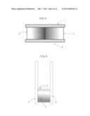
[0024] FIG. 5, 1 is a representation of FIG. 1, 1 as seen from looking at the upright holder from a side view, which is identical to the view from the opposing side.
[0025] FIG. 5, 2 is a representation of FIG. 1, 2 as seen from looking at the upright holder from a side view, which is identical to the view from the opposing side (FIG. 1, 3)
[0026] FIG. 5, 4 is a representation of FIG. 1, 4 as seen from looking at the upright holder from a side view, which is identical to the view from the opposing side.
DESCRIPTION OF THE PREFERRED EMBODIMENT
[0027] Referring to FIGS. 1 and 2, the preferred embodiment of the present invention is comprised of parts 1, 2, 3, and 4; with FIG. 1 representing the completed embodiment. Initially, all parts are cut and removed from a solid material and sanding is recommended for a smooth aesthetic finish.
[0028] Referring to FIG. 2, parts 2 and 3 are adhered with a cyanoacrylate to bond them firmly to one another at a 90 degree angle. This forms the "V" shaped structure which holds the napkins.
[0029] Referring to FIGS. 4 and 5; parts 1 and 4 are then adhered with a cyanoacrylate to bond them parallel to the already bonded parts 2 and 3, with parts 2 and 3 set towards the bottom of parts 1 and 4. The bonded parts 2 and 3 are at a 45 degree angle in parallel relation to parts 1 and 4.
[0030] Dimensionally, referring to FIG. 1, parts 1 and 4 are identical in size. The preferred embodiment of each individual piece is six and one half inches wide by seven inches tall and one half inch deep.
[0031] Referring to FIG. 2, dimensionally, part 2 is four and one half inches in length by two and one quarter inches wide and one half inch deep. Part 3 is four inches in length by two and one quarter inches wide and one half inch deep. This allows for parts 2 and 3 to sit flush with one another as the one half inch depth of part 2 will account for the shorter one half inch length of part 3.
[0032] Dimensionally, the final completed embodiment of the present invention in reference to FIG. 1 is six and one half inches wide by seven inches tall and three and one quarter inch deep.
[0033] In reference to FIGS. 1, 2 and 3, optional ornamental designs as seen on parts 1 and 4 may be included, but it is recommended that aesthetic designs to individual pieces be routed prior to construction of the present invention for ease of assembly.
[0034] Referring to FIGS. 1, 2 and 4, napkins are placed diagonally into the bonded parts 2 and 3 perpendicular to the sidewalls (parts 1 and 4.)
[0035] The above description is of the preferred embodiment, but construction of the present invention is not limited or restricted by the given dimensions. Any solid material may be utilized as well as any adhering process to construct the present invention.
User Contributions:
Comment about this patent or add new information about this topic:
Images included with this patent application:
 |
| New patent applications in this class: | |
| Date | Title |
|---|---|
| 2015-03-05 | Document organizer |
| 2014-01-16 | Greeting card outpost |
| 2012-10-18 | Consumer products |
| 2011-10-27 | Nestable article holder |
| 2011-03-17 | Device for file storage |
| Top Inventors for class "Supports: racks" | |
| Rank | Inventor's name |
|---|---|
| 1 | Stephen N. Hardy |
| 2 | Wen-Tsan Wang |
| 3 | Gregory M. Bird |
| 4 | Shane Obitts |
| 5 | Kaveh Didehvar |