Patent application title: SUPPLEMENTAL BRAKE LIGHT
Inventors:
R. Scott Lunsford (Stony Point, NC, US)
IPC8 Class: AF21S810FI
USPC Class:
362545
Class name: Plural light sources with common housing including light emitting diode
Publication date: 2013-01-10
Patent application number: 20130010490
Abstract:
The present invention is a supplemental brake light in communication with
a brake of a vehicle that includes an existing brake light, a triangular
or inverted triangular casing that is disposed within the existing brake
light and a plurality of LED lights that are housed within the casing. A
second embodiment of the supplemental brake light includes an existing
brake light, a plurality of LED lights that are housed within the
existing brake light and a center LED light disposed within the center of
the existing brake light. A third embodiment of the supplemental brake
light includes a pair of existing brake lights, a generally rectangular
casing positioned between the existing brake lights and a plurality of
LED lights that are disposed within the generally rectangular casing. The
LED lights become brighter and flicker as the brake is increasingly
depressed in all three embodiments.Claims:
1. A supplemental brake light in communication with a brake of a vehicle,
comprising: an existing brake light; a triangular casing with a top tip
and a bottom base that is disposed within said existing brake light; and
a plurality of LED lights that are housed within said triangular casing.
2. The supplemental brake light according to claim 1, wherein said supplemental brake light includes an inverted triangular casing with a bottom tip and a top base.
3. The supplemental brake light according to claim 2, wherein said LED lights vertically move from said bottom tip to said top base as said brake is increasingly depressed.
4. The supplemental brake light according to claim 2, wherein said LED lights become brighter as said brake is increasingly depressed.
5. The supplemental brake light according to claim 2, wherein said top base flickers when said brake is fully depressed.
6. The supplemental brake light according to claim 1, wherein said LED lights form a plurality of rows that vertically move from said bottom base to said top tip as said brake is increasingly depressed.
7. The supplemental brake light according to claim 6, wherein said LED lights become brighter as said brake is increasingly depressed.
8. The supplemental brake light according to claim 1, wherein said top tip flickers when said brake is fully depressed.
9. The supplemental brake light according to claim 1, wherein said LED lights are brighter and utilize a brighter filament than said existing brake light.
10. A supplemental brake light in communication with a brake of a vehicle, comprising: an existing brake light with a perimeter and a center; a plurality of LED lights that are housed within said existing brake light; and a center LED light disposed within said center of said existing brake light.
11. The supplemental brake light according to claim 10, wherein said LED lights form a plurality of internal perimeter rows that move inward toward said center LED light from said perimeter as said brake is increasingly depressed.
12. The supplemental brake light according to claim 11, wherein said internal perimeter rows become brighter as said brake is increasingly depressed.
13. The supplemental brake light according to claim 10, wherein said center LED light flickers when said brake is held in said fully depressed position.
14. The supplemental brake light according to claim 10, wherein said LED lights are brighter and utilize a brighter filament than said existing brake light.
15. The supplemental brake light according to claim 10, wherein said center LED light is brighter than said internal perimeter row LED lights.
16. A supplemental brake light in communication with a brake of a vehicle, comprising: a pair of existing brake lights; a generally rectangular casing positioned between said existing brake lights; and a plurality of LED lights that are disposed within said generally rectangular casing.
17. The supplemental brake light according to claim 16, wherein said LED lights are illuminated from left to right.
18. The supplemental brake light according to claim 17, wherein said LED lights become brighter as said brake is increasingly depressed.
19. The supplemental brake light according to claim 16, wherein said LED lights are brighter than said existing brake lights.
20. The supplemental brake light according to claim 19, wherein said LED lights utilize a brighter filament than said existing brake lights.
Description:
TECHNICAL FIELD & BACKGROUND
[0001] Driving can be a dangerous activity, one that could potentially be injurious or deadly if a serious collision occurs. Currently there are limited alternatives to automotive safety that avoid crashes by providing a supplemental visual alert that notifies a driver when another vehicle is coming to a stop.
[0002] The present invention generally relates to a brake light. More specifically, the invention is a supplemental brake light.
[0003] It is an object of the invention to provide a supplemental brake light that serves as an additional safety brake light.
[0004] It is an object of the invention to provide a supplemental brake light that is illuminated based on the amount of pressure applied to the brakes of a vehicle.
[0005] What is really needed is a supplemental brake light that serves as an additional safety brake light that is illuminated based on the amount of pressure applied to the brakes of a vehicle.
BRIEF DESCRIPTION OF THE DRAWINGS
[0006] The present invention will be described by way of exemplary embodiments, but not limitations, illustrated in the accompanying drawings in which like references denote similar elements, and in which:
[0007] FIG. 1A illustrates a front perspective view of a supplemental brake light, in accordance with one embodiment of the present invention.
[0008] FIG. 1B illustrates a front perspective view of a supplemental brake light, in accordance with one embodiment of the present invention.
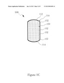
[0009] FIG. 1C illustrates a front perspective view of a plurality of LED lights of a supplemental brake light, in accordance with one embodiment of the present invention.
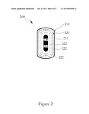
[0010] FIG. 2 illustrates a front perspective view of a supplemental brake light, in accordance with one embodiment of the present invention.
[0011] FIG. 3 illustrates a front perspective view of a supplemental brake light, in accordance with one embodiment of the present invention.
DETAILED DESCRIPTION OF ILLUSTRATIVE EMBODIMENTS
[0012] Various aspects of the illustrative embodiments will be described using terms commonly employed by those skilled in the art to convey the substance of their work to others skilled in the art. However, it will be apparent to those skilled in the art that the present invention may be practiced with only some of the described aspects. For purposes of explanation, specific numbers, materials and configurations are set forth in order to provide a thorough understanding of the illustrative embodiments. However, it will be apparent to one skilled in the art that the present invention may be practiced without the specific details. In other instances, well-known features are omitted or simplified in order not to obscure the illustrative embodiments.
[0013] Various operations will be described as multiple discrete operations, in turn, in a manner that is most helpful in understanding the present invention. However, the order of description should not be construed as to imply that these operations are necessarily order dependent. In particular, these operations need not be performed in the order of presentation.
[0014] The phrase "in one embodiment" is utilized repeatedly. The phrase generally does not refer to the same embodiment, however, it may. The terms "comprising", "having" and "including" are synonymous, unless the context dictates otherwise.
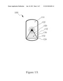
[0015] FIG. 1A illustrates a front perspective view of a supplemental brake light 100, in accordance with one embodiment of the present invention. The supplemental brake light 100 includes an existing brake light 110, a triangular casing 120 and a plurality of LED lights 130. The supplemental brake light 100 is in communication with a brake of a vehicle (not shown).
[0016] The existing brake light 110 can be any suitable brake light of any size or dimensions existing on any suitable type of vehicle. The triangular casing 120 is planar and disposed within the existing brake light 110 and has a top tip 122 and a bottom base 124. The LED lights 130 form a plurality of rows 132 that vertically move from the bottom base 124 to the top tip 122 as pressure is increased on the brakes of a vehicle (not shown). The rows 132 are illuminated and become relatively brighter as the brake pressure is increased and the rows move up the triangular casing 120. The LED lights 130 at the top tip 122 will flicker when the brakes are fully depressed. The LED lights 130 are also relatively brighter and utilize relatively brighter filaments than the existing brake light 110.
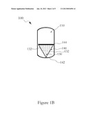
[0017] FIG. 1B illustrates a front perspective view of a supplemental brake light 100, in accordance with one embodiment of the present invention. The supplemental brake light 100 includes an inverted triangular casing 140 with a bottom tip 142 and a top base 144. The inverted triangular casing 140 houses the LED lights 130 and rows 132 that become illuminated and relatively brighter as the brake pressure is increased and the rows 132 move up the inverted triangular casing 140. The LED lights 130 at the top base 144 will flicker when the brakes are fully depressed. The other features of the supplemental brake light 100 in FIG. 1B are identical to the features illustrated in FIG. 1A and described in its description.
[0018] FIG. 1C illustrates a front perspective view of a plurality of LED lights 130 of a supplemental brake light 100, in accordance with one embodiment of the present invention. The LED lights 130 and rows 132 are disposed throughout the existing brake light 110, which includes a top 112 and a bottom 114. The LED lights 130 and rows 132 are illuminated and become relatively brighter as the brake is increasingly depressed and the rows 132 move up from the bottom 114 to the top 112 of the existing brake light 110. This embodiment of the supplemental brake light 100 does not include a triangular casing 120 or an inverted triangular casing 140.
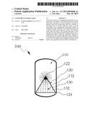
[0019] FIG. 2 illustrates a front perspective view of a supplemental brake light 200, in accordance with one embodiment of the present invention. The supplemental brake light 200 includes an existing brake light 210, a plurality of LED lights 220 and a center LED light 230.
[0020] The existing brake light 210 has a perimeter 212 and a center 214 and can be any suitable brake light of any size or dimensions existing on any suitable type of vehicle. The LED lights 220 form a plurality of internal perimeter rows 222 that move inward from the perimeter 212. The internal perimeter rows 222 become relatively brighter as the brake is increasingly depressed and the internal perimeter rows 222 are illuminated inward from the perimeter 212 of the existing brake light 210. The center LED light 230 is disposed in the center 214 of the existing brake light 210 that the internal perimeter rows 222 are illuminated inward from the perimeter 212 towards. The center LED light 230 is illuminated when the brake is fully depressed and will flicker and is relatively brighter than the internal perimeter rows 222 when the brake is held in a fully depressed position.
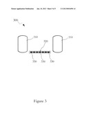
[0021] FIG. 3 illustrates a front perspective view of a supplemental brake light 300, in accordance with one embodiment of the present invention. The supplemental brake light 300 includes a pair of existing brake lights 310, a generally rectangular casing 320 and a plurality of LED lights 330.
[0022] The existing brake lights 310 can be any suitable brake light of any size or dimensions existing on any suitable type of vehicle. The generally rectangular casing 320 is positioned between the existing brake lights 310. The LED lights 330 are disposed within the generally rectangular casing 320 and are illuminated from left to right as the LED lights 330 become relatively brighter as the brake is increasingly depressed.
[0023] The supplemental brake light is intended to prevent rear-end collisions by providing additional brake lights that are solely used to signal when a driver is placing sudden or gradual pressure on the brake. The supplemental brake lights will use LED lights with standard and brighter filaments to notify a driver when the brake is experiencing increased or abrupt pressure that is detected by a sensor that is installed in the brake line. Because the LED lights surround the main brake lights, the supplemental brake light displays a visual diagram that emphasizes the spatial relationship between two vehicles, preventing accidents by allowing a following driver to better foresee any potential hazards. Additional features include an alternative option that features LED lights that surround the main brake lights and illuminate in a series, or sequence of rows, to indicate the different kinds of pressure being applied by the driver. Both of these options are relatively equally effective and will significantly reduce the occurrence of rear-end collisions, thereby saving lives in the process.
[0024] The supplemental brake light offers an additional safety feature that can already be installed in new vehicles but can also be available as an aftermarket accessory. The supplemental brake light is compatible with all suitable vehicle makes and models.
[0025] While the present invention has been related in terms of the foregoing embodiments, those skilled in the art will recognize that the invention is not limited to the embodiments described. The present invention can be practiced with modification and alteration within the spirit and scope of the appended claims. Thus, the description is to be regarded as illustrative instead of restrictive on the present invention.
User Contributions:
Comment about this patent or add new information about this topic:
Images included with this patent application:
 |  |
 |  |
 |  |
| Similar patent applications: | |
| Date | Title |
|---|---|
| 2009-03-12 | People conveyor glass bastustrade lighting |
| 2010-11-18 | Multiple component solid state white light |
| 2012-11-22 | Battery powered lamp socket that supplies energy for led or cfl light bulbs |
| 2012-11-22 | Self-leveling bracket for lighting fixture |
| 2009-11-26 | Electric shock resistant l.e.d. based light |
| New patent applications in this class: | |
| Date | Title |
|---|---|
| 2022-05-05 | Lamp unit and vehicle lamp |
| 2017-08-17 | Lighting device and lighting system |
| 2016-06-23 | Lighting and/or signaling device comprising a plurality of light-emitting diodes |
| 2016-06-16 | Led h4 retrofit lamp unit |
| 2016-05-26 | Illuminated vehicle accessory system |
| Top Inventors for class "Illumination" | |
| Rank | Inventor's name |
|---|---|
| 1 | Shao-Han Chang |
| 2 | Kurt S. Wilcox |
| 3 | Paul Kenneth Pickard |
| 4 | Chih-Ming Lai |
| 5 | Stuart C. Salter |