Patent application title: VAPOR CHAMBER AND METHOD FOR MANUFACTURING THE SAME
Inventors:
Qing-Ping Yan (Shenzhen City, CN)
De-Yu Wang (Shenzhen City, CN)
De-Yu Wang (Shenzhen City, CN)
Jiang-Jun Hu (Shenzhen City, CN)
Jiang-Jun Hu (Shenzhen City, CN)
Assignees:
FOXCONN TECHNOLOGY CO., LTD.
FU ZHUN PRECISION INDUSTRY (SHEN ZHEN) CO., LTD.
IPC8 Class: AF28D1504FI
USPC Class:
16510426
Class name: Liquid fluent heat exchange material utilizing change of state utilizing capillary attraction
Publication date: 2012-09-27
Patent application number: 20120241133
Abstract:
A vapor chamber includes a heat absorbing plate and a heat dissipating
plate attached to the heat absorbing plate. The heat absorbing plate
includes a wick structure thereon facing the heat dissipating plate. The
wick structure defines a plurality of first grooves and a plurality of
second grooves intersecting the first grooves. The heat dissipating plate
forms a hermetically sealed container in cooperation with the heat
absorbing plate. The hermetically sealed container receives the wick
structure therein. Working fluid is sealed inside the container and flows
in the first grooves and the second grooves.Claims:
1. A vapor chamber comprising: a heat absorbing plate for contacting a
heat-generating component, the heat absorbing plate comprising a wick
structure thereon, the wick structure defining a plurality of first
grooves and a plurality of second grooves intersecting the first grooves;
a heat dissipating plate attached on the heat absorbing plate, and
forming a hermetically sealed container in cooperation with the heat
absorbing plate, the hermetically sealed container receiving the wick
structure; and working fluid being sealed inside the container and
flowing in the first grooves and the second grooves.
2. The vapor chamber of claim 1, wherein each of the first grooves is approximately perpendicular to the second grooves.
3. The vapor chamber of claim 1, wherein each of the first grooves and the second grooves has a substantially V-shaped cross-section.
4. The vapor chamber of claim 1, wherein each of the first grooves and the second grooves has a substantially rectangular cross-section.
5. The vapor chamber of claim 1, further comprising an additional wick structure in the container and tightly attached to the heat dissipating plate.
6. The vapor chamber of claim 5, wherein the additional wick structure is metal powders or waved metal wires.
7. The vapor chamber of claim 1, wherein a protrusion integrally extends from the heat absorbing plate toward the heat dissipating plate, the first grooves and the second grooves of the wick structure are defined at the protrusion.
8. The vapor chamber of claim 7, wherein the heat dissipating plate comprises a top plate and two sidewalls extending down from edges of the top plate, the sidewalls soldered in place to edges of the heat absorbing plate.
9. A method for manufacturing a vapor chamber, the method comprising: providing an aluminum heat absorbing plate extruded to define a plurality of first grooves thereon; machining a plurality of second grooves on the heat absorbing plate and intersecting the first grooves; providing a heat dissipating plate and soldering the heat dissipating plate on the heat absorbing plate to form a container; and filling the container with working liquid and sealing the container.
10. The method of claim 9, wherein each of the first grooves is approximately perpendicular to the second grooves.
11. The method of claim 9, wherein each of the first grooves and the second grooves has a substantially V-shaped cross-section.
12. The method of claim 9, wherein each of the first grooves and the second grooves has a substantially rectangular cross-section.
Description:
BACKGROUND
[0001] 1. Technical Field
[0002] The present disclosure relates to vapor chambers and, more particularly, to a vapor chamber having stable and reliable performance and a method for manufacturing such vapor chamber.
[0003] 2. Description of Related Art
[0004] Generally, vapor chambers are used to dissipate and transfer heat generated by electronic components. Vapor chambers include a plate-shaped container, a wick structure formed on inner surfaces of the container, and working fluid sealed inside the container. The working fluid is generally limited by the wick structure and flows in a single direction, thereby negatively influencing heat dissipation efficiency of the vapor chamber.
[0005] What is needed, therefore, is a vapor chamber which can overcome the limitation described.
BRIEF DESCRIPTION OF THE DRAWINGS
[0006] Many aspects of the present embodiments can be better understood with reference to the following drawings. The components in the drawings are not necessarily drawn to scale, the emphasis instead placed upon clearly illustrating the principles of the present embodiments. Moreover, in the drawings, like reference numerals designate corresponding parts throughout the several views.
[0007] FIG. 1 is an assembled, isometric view of a vapor chamber in accordance with a first embodiment of the disclosure.
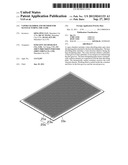
[0008] FIG. 2 is an exploded view of the vapor chamber of FIG. 1.
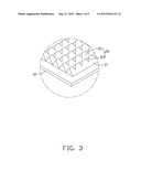
[0009] FIG. 3 is an enlarged view of a circled portion III of FIG. 2.
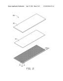
[0010] FIG. 4 is an inverted view of the vapor chamber of FIG. 2.
[0011] FIG. 5 is an isometric view of a vapor chamber in accordance with a second embodiment of the present disclosure.
DETAILED DESCRIPTION
[0012] Referring to FIGS. 1-2, a vapor chamber 100 in accordance with a first embodiment of the present disclosure comprises a heat absorbing plate 10, a heat dissipating plate 30, a first wick structure 20 integrally extending from a top surface of the heat absorbing plate 10 and facing the heat dissipating plate 30, and a second wick structure 40 tightly attached to a bottom surface of the heat dissipating plate 30. The heat dissipating plate 30 covers the heat absorbing plate 10 to form a hermetic container in the vapor chamber 100. Working fluid is hermetically contained in the container of the vapor chamber 100 to act as a heat transfer liquid.
[0013] Referring also to FIG. 3, the heat absorbing plate 10 is made of aluminum. The heat absorbing plate 10 is rectangular and a protrusion 11 integrally extends from a central portion thereof. Outer edges of the heat absorbing plate 10 are exposed for connecting to the heat dissipating plate 30. The first wick structure 20 is integrally formed at the protrusion 11. The first wick structure 20 includes a number of parallel first grooves 21 and a number of parallel second grooves 23 intersecting the first grooves 21. The first grooves 21 are made during forming the protrusion 11. The second grooves 23 are made by machining after the protrusion 11 is formed. Each of the first grooves 21 extends lengthways from one end to an opposite end of the protrusion 11. Each of the first grooves 21 is substantially perpendicular to each of the second grooves 23. Each of the first grooves 21 and the second grooves 23 has a V-shaped cross-section.
[0014] Referring to FIG. 4, the heat dissipating plate 30 is made of metal having good thermal conductivity, such as aluminum. The heat dissipating plate 30 includes a top plate 31 and two sidewalls 33 extending down from edges of the top plate 31. The top plate 31 is rectangular and corresponds to the heat absorbing plate 10. The sidewalls 33 are soldered in place to the exposed edges of the heat absorbing plate 10. The second wick structure 40 can be made of metal powders such as copper powders via sintering, or can be made by weaving of metal wires.
[0015] In operation of the vapor chamber 100, heat generated by an electronic component is absorbed by the heat absorbing plate 10. The heat absorbed by the heat absorbing plate 10 vaporizes the working fluid in the vapor chamber 100. The vapor flows along the intersecting first grooves 21 and the second grooves 23 to the heat dissipating plate 30. The vapor exchanges the heat to the heat dissipating plate 30, and in so doing, condenses into working fluid and returns back by the second wick structure 40 to the heat absorbing plate 10 for another cycle. Since the first grooves 21 and the second grooves 23 intersect each other, the vapor can quickly flow along the first grooves 21 and the second grooves 23, and the working fluid can be uniformly guided back to the heat absorbing plate 10 for another cycle, thereby improving the heat dissipation efficiency of the vapor chamber 100.
[0016] An exemplary method for manufacturing a vapor chamber 100 includes steps as follows:
[0017] Firstly, a heat absorbing plate 10 is provided. The heat absorbing plate 10 is made of aluminum. The heat absorbing plate 10 is extruded to form the protrusion 11 with a plurality of first grooves 21 defined therein;
[0018] Secondly, a plurality of second grooves 23 are machined into the heat absorbing plate 10 intersecting the first grooves 21, thereby forming the heat absorbing plate 10 with a first wick structure 20 having the first grooves 21 and the second grooves 23;
[0019] Thirdly, a heat dissipating plate 30 is provided with a second wick structure 40 tightly attached to a bottom surface thereof. The heat dissipating plate 30 is soldered to the heat absorbing plate 10 to form a container; and
[0020] Finally, filling the container with working liquid and sealing the container.
[0021] Referring to FIG. 5, a vapor chamber in accordance with a second embodiment of the present disclosure comprises a heat absorbing plate 10a. The heat absorbing plate 10a includes a first wick structure 20a defining a number of parallel first grooves 21a and a number of parallel second grooves 23a. Different from the vapor chamber 100 of the first embodiment of the present disclosure, the first grooves 21a and the second grooves 23a each have a rectangular cross-section.
[0022] It is to be understood, however, that even though numerous characteristics and advantages of certain embodiments have been set forth in the foregoing description, together with details of the structures and functions of the embodiments, the disclosure is illustrative only, and changes may be made in detail, especially in matters of shape, size, and arrangement of parts within the principles of the disclosure to the full extent indicated by the broad general meaning of the terms in which the appended claims are expressed.
User Contributions:
Comment about this patent or add new information about this topic:
Images included with this patent application:
 |  |
 |  |
 |  |
| Similar patent applications: | |
| Date | Title |
|---|---|
| 2011-07-21 | Vapor chamber and method for manufacturing the same |
| 2012-12-06 | Heat storage member and method for manufacturing the same |
| 2011-08-11 | Vapor chamber and edge-sealing structure thereof |
| 2011-06-02 | Cooling device and method for the manufacturing thereof |
| 2011-11-17 | Air conditioner and method for controlling the same |
| New patent applications in this class: | |
| Date | Title |
|---|---|
| 2019-05-16 | Method for preparing porous wick and product prepared by the same |
| 2019-05-16 | Semiconductor device assembly with vapor chamber |
| 2019-05-16 | Straight-through structure of heat dissipation unit |
| 2018-01-25 | Diphasic cooling loop with satellite evaporators |
| 2017-08-17 | Heat pipe |
| New patent applications from these inventors: | |
| Date | Title |
|---|---|
| 2012-12-06 | Electronic device with heat pipe chamber cover for dissipating heat |
| 2012-12-06 | Portable electronic device with heat pipe |
| Top Inventors for class "Heat exchange" | |
| Rank | Inventor's name |
|---|---|
| 1 | Levi A. Campbell |
| 2 | Chun-Chi Chen |
| 3 | Tai-Her Yang |
| 4 | Robert E. Simons |
| 5 | Richard C. Chu |