Patent application title: METHODS FOR MAKING A SENSITIVE RESONATING BEAM ACCELEROMETER
Inventors:
John S. Starzynski (North Bend, WA, US)
Assignees:
HONEYWELL INTERNATIONAL INC.
IPC8 Class: AH04R3100FI
USPC Class:
7351438
Class name: Speed, velocity, or acceleration acceleration determination utilizing inertial element including an elastic support for an inertial element (e.g., spring)
Publication date: 2012-09-13
Patent application number: 20120227495
Abstract:
A method of making a resonating beam accelerometer (RBA). In an example
process, a proof mass device and resonators are created from a quartz
material. A direct bond is formed between the proof mass and the
resonators by applying a predefined amount of pressure at a predefined
temperature for a predefined amount of time. One or more damping plates
are created from a quartz material. A direct bond is formed between the
damping plates and the proof mass device. The proof mass device is
created by applying a predefined amount of pressure at pressure at
temperature to two bases, two proof mass portions, and a flexure. The
proof mass bases are on opposite sides of the flexure. The proof mass
portions are on opposite sides of the flexure. A gap is present between
the proof mass bases and the proof mass portions.Claims:
1. A method of making a resonating beam accelerometer (RBA), the method
comprising: creating a proof mass device from a first quartz material;
creating at least two resonators from a second quartz material; placing
the proof mass device and the at least two resonators in a tooling device
configured to stabilize movement between the proof mass device and the at
least two resonators; and applying a predefined amount of pressure at a
predefined temperature for a predefined amount of time to the at least
two resonators and the proof mass device, thereby forming a direct bond
between the proof mass device and each of the resonators, wherein the
first quartz material has a coefficient of thermal expansion (CTE) that
is within a threshold amount of a CTE of the second quartz material.
2. The method of claim 1, wherein the CTEs of the first and second quartz materials are identical.
3. A resonating beam accelerometer (RBA) device, the method comprising: two proof mass bases; two moveable proof mass portions; and a flexure layer, wherein one of the two proof mass bases is directly bonded to a first side of a first end of the flexure layer and the other of the two proof mass bases is directly bonded to a second side of the first end of the flexure layer, wherein one of the two proof mass portions is directly bonded to the first side of a second end of the flexure layer and the other of the two proof mass portions is directly bonded to the second side of the second end of the flexure layer, wherein a gap is formed between the bonded proof mass basses and the proof mass portions, wherein the two proof mass bases, the two moveable proof mass portions and the flexure layer are formed of materials having coefficient of thermal expansion (CTE) that are within a threshold amount of each other.
4. The device of claim 3, wherein the CTEs of the two proof mass bases, the two moveable proof mass portions and the flexure layer are identical.
Description:
PRIORITY CLAIM
[0001] This application is a continuation of U.S. patent application Ser. No. 12/751,157 filed on Mar. 31, 2010 and is incorporated herein by reference.
BACKGROUND OF THE INVENTION
[0003] The sensitivity of an accelerometer can be degraded by creep of bonded joints. It can also be degraded by a difference in the coefficient of thermal expansion (CTE) between the bonding solder or glue and the bonded pieces.
[0004] The resonators and damping plates are typically attached employing either solder or glue. Glue, and to a lesser degree solder, may creep (the tendency of a solid material to slowly move or deform under the influence of stress), thus degrading the sensitivity of the accelerometer.
[0005] In addition, the sensitivity of an accelerometer can be degraded by machining imperfections in the proof mass hinge. Machining the hinge can introduce microcracking in the hinge, resulting in loss of accelerometer sensitivity and/or hinge failure.
[0006] One way to manufacture a hinge is to glue or solder a thin blank between four proof mass sections. Once again, creep of the solder or glue, as well as the CTE mismatched between the solder or the glue and the proof mass material, will degrade sensitivity.
SUMMARY OF THE INVENTION
[0007] The present invention provides a method of making a resonating beam accelerometer (RBA). In an example process, a proof mass device and resonators are created from a quartz material. A direct bond is formed between the proof mass and the resonators by applying a predefined amount of pressure at a predefined temperature for a predefined amount of time.
[0008] In one aspect of the invention, one or more damping plates are created from a quartz material. A direct bond is formed between the damping plates and the proof mass device by applying a predefined amount of pressure at a predefined temperature for a predefined amount of time.
[0009] In another aspect of the invention, the proof mass device is created by applying a predefined amount of pressure at a predefined temperature for a predefined amount of time to two proof mass bases, two moveable proof mass portions, and a flexure layer, thereby forming a direct bond between the parts. The proof mass bases are located on opposing sides of the flexure layer at one end of the flexure layer. The moveable proof mass portions are located on opposing sides of the flexure layer at another end of the flexure layer. A gap is present between the proof mass bases and the moveable proof mass portions.
BRIEF DESCRIPTION OF THE DRAWINGS
[0010] Preferred and alternative embodiments of the present invention are described in detail below with reference to the following drawings:
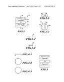
[0011] FIG. 1 is a side cross-sectional view of a resonating beam accelerometer (RBA) formed in accordance with an embodiment of the present invention;
[0012] FIGS. 2-1, 2-2 are top and side views of a proof mass used in the RBA of FIG. 1;
[0013] FIGS. 3-1, 3-2 are side and top views of a resonator that is used in the RBA shown in FIG. 1;
[0014] FIGS. 4-1, 4-2, 4-3 are side, bottom, and top views of a top damping device used in the RBA shown in FIG. 1;
[0015] FIG. 5 is an exploded view of the RBA of FIG. 1;
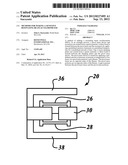
[0016] FIG. 6 illustrates direct bonds of an exemplary RBA;
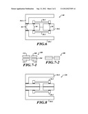
[0017] FIGS. 7-1, 7-2 are side views showing construction of a proof mass according to an alternate embodiment of the present invention; and
[0018] FIG. 8 is a side view of an RBA incorporating the proof mass of FIG. 7-2.
DETAILED DESCRIPTION OF THE INVENTION
[0019] The present invention provides a sensitive resonating beam accelerometer (RBA) and a method for making a sensitive RBA. RBAs measure acceleration as a function of the frequency difference between two sets of vibrating quartz beams.
[0020] As shown in FIG. 1, an exemplary RBA 20 includes two sets of resonators 26, 28, a hinged proof mass 30, and two damping plates 36, 38. The damping plates 36, 38 damp out the oscillation of the proof mass 30. All the components are manufactured from the same type of material typically fused silica (amorphous quartz) or single crystal quartz.
[0021] FIGS. 2-1, 2-2 are top and side views of the proof mass 30. FIGS. 3-1, 3-2 are top and side views of the top set of resonators 26. FIGS. 4-1, 4-2, 4-3 are top, bottom, and side views of the top damping plate 36. FIG. 5 is an exploded view of the RBA 20.
[0022] The proof mass 30 includes a thinned region 40 that spans across two thicker portions 42, 44. The thinned region 40 acts as a bending point (flexure) for the end portions 42, 44 of the proof mass 30. The resonators 26, 28 are attached, perpendicular to the hinge, between each of the portions 42, 44 of the proof mass 30. The damping plates 36, 38 are attached to both the top and bottom sides of the stationary portion 42 of the proof mass 30. When the RBA 20 experiences an acceleration force, the movable portion 44 of the proof mass 30 will bend and one set of the resonators 26, 28 will increase in frequency and the other set will decrease in frequency. The magnitude of the acceleration is determined by these frequency changes.
[0023] Prior to assembly of the RBA components, the joining surfaces are polished. The parts are polished using standard mechanical glass polishing techniques. Then the surfaces are cleaned in a solution containing water, hydrogen peroxide, and ammonium hydroxide and then dried. The components are placed and held together at a predefined pressure of between 0.2 and 40 atmospheres with tooling (not shown) and heated to a temperature above 200° C. for several hours. Atoms from the components will interdiffuse and form a direct bond. This bond will not creep and if the joined parts are of the same material, there will be no CTE mismatch between the bond and the joined pieces. Direct bonding allows for joining of two materials without an intermediate layer as in soldering or gluing. The direct bond of two similar single-crystal materials results in the crystal lattices being joined together.
[0024] As shown in FIG. 6, an RBA 80 has been assembled using direct bonding. Damping plates 36-1, 38-1 and resonators 26-1, 28-1 are direct bonded to a proof mass 30-1 according to the process described above. Direct bonds 84 now exist between the parts.
[0025] FIGS. 7-1 and 7-2 show exploded and assembled views of a proof mass 100 fabricated with direct bonding. The proof mass 100 includes five pieces: a hinge layer 104, between 0.001 to 0.010 inches thick; two proof mass ends 108, 110 between 0.050 to 0.250 inches thick; and two proof mass bases 112, 114 between 0.050 to 0.250 inches thick. The proof mass 100 is created by applying the direct bonding technique described above. The result is a direct bond created between the ends 108, 110, and bases 112, 114, and the hinge 104.
[0026] As shown in FIG. 8, an RBA 120 is assembled by employing direct bonding using the proof mass 100 shown in FIG. 7-2. Damping plates 36-2, 38-2 and resonators 26-2, 28-2 are direct bonded to the proof mass 100. The highlighted lines 124 indicate where direct bonds occur.
[0027] An example process for performing a direct bond includes placing the resonators, damping plates and proof mass into a tooling device that keeps all the parts in proper position. The tooling device also allows for pressure 10-50 lbs/in2 to be applied between the parts. Then, temperature is raised over a two hour period to 450°, held at 450° for eight hours, then lowered to room temperature the last two hours. Only pressures and temperatures may be used in order to affect direct bonds to occur between like materials.
[0028] While the preferred embodiment of the invention has been illustrated and described, as noted above, many changes can be made without departing from the spirit and scope of the invention. Accordingly, the scope of the invention is not limited by the disclosure of the preferred embodiment. Instead, the invention should be determined entirely by reference to the claims that follow.
User Contributions:
Comment about this patent or add new information about this topic:
Images included with this patent application:
 |  |
 |
| Similar patent applications: | |
| Date | Title |
|---|---|
| 2012-06-28 | Method and calibration mask for calibrating a position measuring apparatus |
| 2010-07-22 | System and method for increased flux density d'arsonval mems accelerometer |
| 2008-10-30 | Method of making a deposit on an sic-covered substrate |
| 2011-07-28 | Methods for detecting vitamin c by mass spectrometry |
| 2012-07-05 | Method and diagnostic device for diagnosing a heatable exhaust gas sensor of an internal combustion engine |
| New patent applications in this class: | |
| Date | Title |
|---|---|
| 2016-04-07 | Micro inertial measurement system |
| 2015-10-29 | Micro-electromechanical device comprising a mobile mass that can move out-of-plane |
| 2014-06-26 | Detection structure for a z-axis resonant accelerometer |
| 2014-02-13 | Inertial sensing device |
| 2013-09-26 | Apparatus and method for providing an in-plane inertial device with integrated clock |
| New patent applications from these inventors: | |
| Date | Title |
|---|---|
| 2015-09-24 | Resonating beam accelerometer |
| 2012-09-20 | Methods and apparatus for improving performance of an accelerometer |
| 2011-10-06 | Methods for making a sensitive resonating beam accelerometer |
| Top Inventors for class "Measuring and testing" | |
| Rank | Inventor's name |
|---|---|
| 1 | Anthony D. Kurtz |
| 2 | Alfred Rieder |
| 3 | Johannes Classen |
| 4 | Manus P. Henry |
| 5 | Heewon Jeong |