Patent application title: MOBILE EXERCISE DEVICE
Inventors:
Rob Williams
IPC8 Class: AA63B2100FI
USPC Class:
482132
Class name: User manipulated force resisting apparatus, component thereof, or accessory therefor utilizing force resistance generated by user only rolled by or against user
Publication date: 2012-08-23
Patent application number: 20120214652
Abstract:
A mobile exercise device includes a body and a plurality of glide
members. The body includes a pair of parallel ridges defining an
elongated rectangular centre portion, wherein respective length and width
dimensions of the centre portion are sized to enable a user to stand with
one foot positioned longitudinally on the centre portion/ The centre
portion further includes a transversally oriented elongated opening sized
to receive fingers of a user's hand, to thereby permit a user to grasp
the centre portion. The glide members are affixed to the body outboard of
the ridges, and facilitate omnidirectional movement of the device across
a floor surface. The glide members further define a clearance distance
between the centre portion and the floor surface which is larger than an
expected thickness of the user's fingers.Claims:
1. A mobile exercise device comprising: a body having a pair of parallel
ridges defining an elongated rectangular centre portion, wherein
respective length and width dimensions of the centre portion are sized to
enable a user to stand with one foot positioned longitudinally on the
centre portion, the centre portion further including a transversally
oriented elongated opening sized to receive fingers of a user's hand, to
thereby permit a user to grasp the centre portion; and a plurality of
glide members affixed to the body outboard of the ridges, the glide
members facilitating omnidirectional movement of the device across a
floor surface, and defining a clearance distance between the centre
portion and the floor surface, the clearance distance being larger than
an expected thickness of the user's fingers.
2. The mobile exercise device as claimed in claim 1, wherein a height dimension of the ridges is selected to guide a user's appendage within the rectangular centre portion.
3. The mobile exercise device as claimed in claim 2, wherein the ridges are provided as respective bent portions of the body, and wherein the height dimension is approximately 1/2 inch.
4. The mobile exercise device as claimed in claim 2, wherein the ridges are provided as a pair of opposed walls, and wherein the height dimension is between approximately 1/2 inch and approximately 1 inch.
5. The mobile exercise device as claimed in claim 1, wherein the glide members comprise any one or more of: sliders; roller balls and casters.
6. The mobile exercise device as claimed in claim 1, further comprising a non-slip material affixed to the center portion.
7. The mobile exercise device as claimed in claim 1, wherein each glide member is affixed to a respective peripheral arm of the body.
8. The mobile exercise device as claimed in claim 7, wherein the peripheral arms are co-planar with the center portion of the body.
9. The mobile exercise device as claimed in claim 7, wherein the peripheral arms are not co-planar with the center portion of the body.
Description:
CROSS-REFERENCE TO RELATED APPLICATIONS
[0001] This application is based on, and claims benefit of, U.S. provisional patent application No. 61/445,226 filed Feb. 22, 2011, the entire content of which is hereby incorporated herein by reference.
MICROFICHE APPENDIX
[0002] Not Applicable.
TECHNICAL FIELD
[0003] The present invention relates to an exercise device, and in particular to a mobile exercise device usable for conditioning the muscles of a user.
BACKGROUND
[0004] Mobile exercise devices of the type designed to move across a floor during use are known in the art.
[0005] For example, in U.S. Pat. No. 5,632,707 (Daniel et al.) discloses an upper torso exerciser in which a handle is secured to a base that is supported by rollers that enable omnidirectional motion across a floor. U.S. Pat. No. 6,942,605 (Sukhovitsky) discloses mobile exercise equipment in which four independent units are individually designed to be secured to a user's feet, knees, elbows and hands by means of straps and specially-shaped fittings. International patent publication No. 2009/075493 (An et al) discloses an exercise machine having a generally triangular shape, that is designed to be held by the user's hand, or to receive the user's foot.
[0006] All of the above prior art devices suffer disadvantages in that they tend to be mechanically complex, which both increases costs and tends to reduce the ruggedness of the device. Additionally, many of the prior art devices utilize specialized fittings such has hand grips, fittings or straps for securing the device to various appendages of the user's. Such specialized arrangements are undesirable, because they reduce versatility, and so limit the range of exercises that can be performed with the device.
[0007] A mobile exercise device that overcomes at least some of the above limitations of the prior art remains highly desirable.
SUMMARY
[0008] An aspect of the present invention provides a mobile exercise device comprising: a body and a plurality of glide members. The body includes a pair of parallel ridges defining an elongated rectangular centre portion, wherein respective length and width dimensions of the centre portion are sized to enable a user to stand with one foot positioned longitudinally on the centre portion/ The centre portion further includes a transversally oriented elongated opening sized to receive fingers of a user's hand, to thereby permit a user to grasp the centre portion. The glide members are affixed to the body outboard of the ridges, and facilitate omnidirectional movement of the device across a floor surface. The glide members further define a clearance distance between the centre portion and the floor surface which is larger than an expected thickness of the user's fingers.
BRIEF DESCRIPTION OF THE DRAWINGS
[0009] Representative embodiments of the invention will now be described by way of example only with reference to the accompanying drawings, in which:
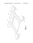
[0010] FIG. 1 is a perspective view illustrating a mobile exercise device in accordance with a representative embodiment of the of the present invention;
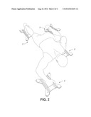
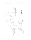
[0011] FIGS. 2 and 3 illustrate the mobile exercise device of FIG. 1 in use; and
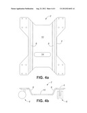
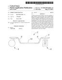
[0012] FIGS. 4a-b are top and end views, respectively, of a mobile exercise device in accordance with a second representative embodiment of the of the present invention.
[0013] It will be noted that throughout the appended drawings, like features are identified by like reference numerals.
DETAILED DESCRIPTION
[0014] In very general terms, embodiments of the present invention provide a mobile exercise device that is versatile, mechanically simple and therefore highly robust and cost effective.
[0015] Referring to FIG. 1, the mobile exercise device 2 generally comprises a star or X-shaped body 4 and a set of glide members 6, which enable omnidirectional movement of the body across a floor surface.
[0016] The body 4 generally comprises a pair of parallel ridges 8 defining an elongated rectangular centre portion 10 including a transversally oriented elongated opening 12. The centre portion is generally flat, and has length and width dimensions that are sized to enable a user to stand with one foot positioned longitudinally on the centre portion. This size is beneficial in that it is large enough to receive any of a variety of appendages (such as, for example, the feet (with or without shoes), hands, forearms or knees) while at the same time keeping the overall size of the exercise device small enough to be easily controlled by the user. In the illustrated embodiments, the center portion 10 has a length of about 10 inches, and width of about 4 inches, but these dimensions are not essential. The ability of the centre portion to receive any one or several different appendages of the user provides great versatility because it enables the device to be used in a wide range of different types of exercises, and with varying degrees of difficulty.
[0017] As may be appreciated, the body may be composed of any suitably rigid material. In some embodiments, the body may be formed out of a piece of metal plate, for example by stamping. In such cases, any suitable metal may be used, including steel or aluminium. On the other hand, the body may be formed of other suitable materials (such as, for example, fiber-reinforced plastic) if desired.
[0018] The parallel ridges bordering the centre portion are designed to enhance a user's control and balance while using the device, by retaining their appendage within the centre portion. As a result, a user can perform exercises with security that they will not fall off the sides of the device, which allows for confident performance of high-speed, sport-specific movements. In the embodiment of FIGS. 1-3, the parallel ridges 8 are provided as a bent portion of the body, and may have a height of about 1/2 inch above the center portion 10. In the embodiment of FIGS. 4a-b, the parallel ridges 8 are provided as opposed walls extending upwardly from the center portion 10 such that the body 4 has a trough-shape. In this embodiment, the walls may have a height of between 1.5 and 1 inch, but these dimensions are not essential.
[0019] For example, FIGS. 2 and 3 illustrate a possible exercise in which the user places each hand and foot on a respective device in accordance with the invention, and then performs a crawling motion. Varying the height at which the body is held off of the floor, and the amount of extension of the hands and feet during the exercise changes the intensity of the exercise. As may be seen in FIGS. 2 and 3, the parallel ridges can engage the user's foot and thereby help prevent the user's foot from falling off the device during the exercise. This increases safety and the user's sense of control during the exercise, which in turn gives the user confidence to concentrate on performing the exercise to maximum effect. An advantage of the present invention is that this security is achieved without the need for special straps, fittings or other devices to attach the device to the user's foot.
[0020] If desired, a non-slip material may be affixed to the centre portion to further improve security and safety.
[0021] As noted above, the centre portion further includes a transversally oriented elongated opening sized to receive the fingers of a user's hand, to thereby permit a user to grasp the centre portion, as may be seen in FIG. 2. This arrangement is beneficial, in that it enables the user to easily grasp the device, which helps improve the user's control while performing an exercise.
[0022] The glide members are affixed to peripheral arms of the body 4 so as to maximize stability, and can be provided as any suitable arrangement permitting omnidirectional movement of the device across a floor surface with minimal friction. It is considered desirable to achieve as low friction as possible, as resistance against movement of the exercise device tends to interfere with a user's performance of various exercise movements. Any suitable slides, roller balls, casters or the like may be used as the glide members. In order to enhance stability of the exercise device, it is considered desirable to configure the body and the glide members such that the centre portion is a low as possible. However, it is important that the glide members also define a clearance distance between the floor surface and the center portion, which is large enough to ensure that the user's fingers will not contact the floor during use of the device, as may be seen in FIGS. 2 and 3. This may be ensured by suitable positioning of the arms on which each glide member 6 is mounted. For example, in the embodiment of FIGS. 1-3, the glide members 6 are provided as roller balls having a comparatively low height. Accordingly, adequate clearance under the center portion 10 is ensured by positioning the peripheral arms approximately co-planar with the center portion 10. Conversely, FIGS. 4a and 4b illustrate an embodiment in which the glide members 6 are provided as casters, which are comparatively tall. In this case, the peripheral arms can be positioned above the plane of the center portion 10, so as to lower the center of gravity (and so improve stability in use), while still ensuring adequate clearance distance between the floor surface and the center portion 10.
[0023] The embodiments of the invention described herein are intended to be illustrative only, and shall not be considered as limiting the scope of the invention, which is therefore intended to be limited solely by the scope of the appended claims.
User Contributions:
Comment about this patent or add new information about this topic:
Images included with this patent application:
 |  |
 |  |
 |
| Similar patent applications: | |
| Date | Title |
|---|---|
| 2009-05-07 | Mobile exercise enhancement with virtual competition |
| 2009-09-24 | Seat mountable exercise device |
| 2012-02-16 | Motorless treadmill stepper exercise device |
| 2009-12-10 | Portable exercise device |
| 2010-03-04 | Portable exercise device |
| New patent applications in this class: | |
| Date | Title |
|---|---|
| 2016-06-23 | Exercise device |
| 2016-06-16 | Full body exercise equipment |
| 2016-05-19 | Therapeutic, fitness, and sports enhancement device |
| 2016-05-12 | Exercise roller device with removably fixable support |
| 2016-04-14 | Exercise device |
| Top Inventors for class "Exercise devices" | |
| Rank | Inventor's name |
|---|---|
| 1 | William T. Dalebout |
| 2 | Scott R. Watterson |
| 3 | Raymond Giannelli |
| 4 | Leao Wang |
| 5 | Bruce Hockridge |