Patent application title: Portable soccer foot skill and agility training mat
Inventors:
Marta Kristine Laird (Farmington Hills, MI, US)
IPC8 Class: AA63B6900FI
USPC Class:
473446
Class name: Playing field or court game; game element or accessory therefor other than projector or projectile, per se practice or training device for game using apertured or pocketed goal or target (e.g., for hockey, soccer, polo, lacrosse, etc.)
Publication date: 2012-07-12
Patent application number: 20120178553
Abstract:
An apparatus to train athletes to increase control of a soccer ball,
increase dribbling skills and develop foot speed and agility all
essential to the sport. This apparatus consists of a mat with cones
placed through it. The athlete dribbles the soccer ball in between the
obstacles to develop foot control over the ball.Claims:
1. Agility training and foot skill development are very important for
athletes who want to improve their ability to play soccer, A very common
way to do training for soccer is to place small plastic cones, resembling
traffic cones in a pattern on a generally flat surface, The athlete in
training either dribbles a soccer ball with his or her feet between the
cones or simply runs in a zig-zag pattern around and among the cones,
Such exercise aids muscular development, helps the athlete improve
balance and improves the athlete's ability to change direction very
quickly while running, Please see U.S. Pat. No. 5,669,883 for a
description of the use of the plastic cones and some of the training
methods used, Typically, these cones are about 250 mm tall and about 125
mm in diameter with a very blunt "point" at the top, A flange extending
several inches from the base of the cone serves to add weight to the base
of the cone to help it to stand up straight and stay in place, However,
it becomes difficult to keep the cones in their desired positions as the
athletes do their training, No matter how careful an athlete might be, he
or she will eventually touch or kick a cone, causing it to move as the
athlete tries to dribble the soccer ball or run zig-zag pattern between
and around the cones, While it would be possible to attach the cones to
the surface on which they are placed, such as a gym floor, mat or grass
field, this extra step of attachment limits the portability of the
training apparatus, Whenever the apparatus is disassembled for storage or
assembled for use, whatever was used to anchor the cones must be detached
or attached, perhaps with tools, Attaching the cones to a portable mat
makes it very difficult to roll the mat up for transportation or storage,
The object of this invention is a portable soccer training mat which is
very easy to set up and take down but provides a way to hold the cones in
their desired positions without requiring attachment to the generally
flat surface on which the mat is placed or directly to the mat itself.Description:
DRAWINGS:
[0001] FIGS. 1, 2, 3, 4
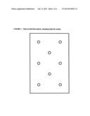
[0002] FIG. 1: View of the mat from above, showing holes for cones.
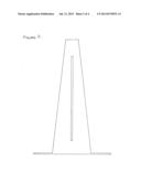
[0003] FIG. 2: Cone 9''×3 at base with stress line 2 sides, these are inserted into the mat.
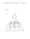
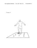
[0004] FIG. 3: Cones in mat with rope latter attached to cone for quick step drills.
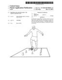
[0005] FIG. 4: Mat with cones minus rope to be used with soccer ball for foot control and agility.
[0006] The invention is comprised of a mat and a set of cones. The mat is made of artificial turf, of the type commonly used outdoors on football fields. This artificial turf has coarse fibers, usually green in color and resembling grass protruding upward from a rubber backing underneath. The overall thickness is approximately 20 mm.
[0007] The mat has approximately 8 circular holes cut in it at the places where a cone is desired, as shown in FIG. 1, below. These holes are approximately 75 mm in diameter.
[0008] The cones are a truncated cone shape about 250 mm high, about 25 mm diameter at the top and about 75 mm wide at the base. See FIG. 2, below. A circular flange, perpendicular to the major axis of the cone, surrounds the base of the cone and is firmly attached to it. The diameter of this flange is approximately 150 mm. The cones can be made of any of the different materials, such as wood, plastic or metal. The cones can either be hollow or solid.
[0009] To set-up the practice mat, the cones are placed first on the generally flat surface and then the mat is placed over them so that the holes in the mat line-up with the cones. See FIG. 4, below. The holes in the mat are sized so they fit closely, but not tightly around the cones at their bases as the mat placed down onto the generally flat surface.
[0010] In use, the weight of the mat plus the weight of the athlete on the mat nearby to the cone keeps the cone in place even if it is kicked or pushed by the athlete. Thus the athlete can concentrate on achieving maximum speed in an agility drill without worry of dislodging or moving a cone.
[0011] A number of variations are possible within the inventive concept. For example, heavy string or light rope can be strung between the tops of the cones as shown in FIG. 3. Such an arrangement forces the athlete to step over the rope as he or she runs among the cones. This exercise improves strength and endurance.
[0012] Other variations of the inventive concept include different size cones (shorter, taller and different diameters) and different patterns of arrangement of the cones. Within a pattern of cones some cones can be bigger or smaller than others. The size, shape and thickness of the flange at the base of the cones can be varied to optimize their ability to stay in place under the mat.
[0013] The inventive concept is devised for portability ie, easy roll and storage. Also the materials and the construction are designed to allow for indoor and/or outdoor use.
User Contributions:
Comment about this patent or add new information about this topic:
| People who visited this patent also read: | |
| Patent application number | Title |
|---|---|
| 20140111822 | IMAGE FORMING APPARATUS CAPABLE OF CONTROLLING POWER SUPPLIES TO RESPECTIVE PARTS THEREOF, AND CONTROL METHOD AND STORAGE MEDIUM THEREFOR |
| 20140111821 | USER TERMINAL APPARATUS AND METHOD OF CONTROLLING THEREOF |
| 20140111820 | USER TERMINAL APPARATUS AND METHOD OF CONTROL THEREOF |
| 20140111819 | PRINTING APPARATUS AND METHOD OF CONTROLLING THE SAME AND STORAGE MEDIUM |
| 20140111818 | Data Flow to a Printing Device |
Images included with this patent application:
 |  |
 |  |
 |  |
| Similar patent applications: | |
| Date | Title |
|---|---|
| 2010-03-25 | Soccer ball and removable spin training tether |
| 2012-07-12 | Soccer goal that is movable and has improved assembly features |
| 2012-08-16 | Devices and assemblies for repetitively practicing a billiard shot |
| 2009-06-11 | Sports skills training apparatus |
| 2010-03-04 | Racket handle insert and corresponding handle and racket |
| New patent applications in this class: | |
| Date | Title |
|---|---|
| 2019-05-16 | Exercise apparatus for ball game |
| 2017-08-17 | Ball net structure with alterable base |
| 2016-09-01 | Hockey skills training system and method of using the same |
| 2016-07-14 | Athletic training device |
| 2016-06-16 | Soccer training method |
| Top Inventors for class "Games using tangible projectile" | |
| Rank | Inventor's name |
|---|---|
| 1 | Michael J. Sullivan |
| 2 | Brian Comeau |
| 3 | Derek A. Ladd |
| 4 | David A. Bulpett |
| 5 | Mark L. Binette |