Patent application title: COOLANT TEMPERATURE CONTROLLING SYSTEM FOR ENGINE PERFORMANCE TEST
Inventors:
Shengjun Jia (Beijing, CN)
Wei Yin (Beijing, CN)
Peng Wang (Beijing, CN)
Peng Wang (Beijing, CN)
IPC8 Class: AF01P900FI
USPC Class:
165 51
Class name: Heat exchange structural installation engine
Publication date: 2012-05-24
Patent application number: 20120125564
Abstract:
The present invention provides a coolant temperature control system for
engine performance test, comprising an internal coolant circulation
system, a heat exchange unit, a temperature monitoring and control unit,
and an external coolant circulation system, wherein, the internal coolant
circulation system and the external coolant circulation system are
connected to the heat exchange unit respectively, and the internal
coolant circulation system is connected to the engine; the temperature
monitoring and control unit is connected to the internal coolant
circulation system, the heat exchange unit, and the external coolant
circulation system respectively, and the internal coolant circulation
system is a closed internal circulation system. A vapor exhaust pipe
connects the water channel in the engine cylinder head to an expansion
water tank; a bypass pipe and a bypass valve are mounted to the water
inlet and water outlet of the engine.Claims:
1. A coolant temperature control system for engine performance test,
comprising an internal coolant circulation system, a heat exchange unit,
a temperature monitoring and control unit, and an external coolant
circulation system, wherein, the internal coolant circulation system and
the external coolant circulation system are connected to the heat
exchange unit respectively, and the internal coolant circulation system
is connected to the engine; the temperature monitoring and control unit
is connected to the internal coolant circulation system, the heat
exchange unit, and the external coolant circulation system; characterized
in that, the internal coolant circulation system is a closed internal
circulation system provided with a bypass unit for reducing the
difference between water inlet pressure and water outlet pressure of the
internal coolant circulation system, the bypass unit comprises a bypass
pipe and a bypass valve, the bypass valve is mounted on the bypass pipe,
and the bypass pipe communicates the engine water inlet pipe with the
engine water outlet pipe.
2. The coolant temperature control system according to claim 1, characterized in that, the closed internal circulation system comprises the engine water outlet pipe, an expansion water tank, a heat exchange pipe, the engine water inlet pipe, and the bypass unit, which are connected in sequence; the engine water outlet pipe is connected to the water outlet of the engine; the engine water inlet pipe is connected to the water inlet of the engine; the heat exchange pipe is connected to the heat exchange unit.
3. The coolant temperature control system according to claim 2, characterized in that, the closed internal circulation system further comprises a vapor exhaust unit which comprises an extension pipe and an vapor exhaust pipe, wherein, one end of the extension pipe is connected to the top of the expansion tank, and the other end of the extension pipe is provided with a valve; the vapor exhaust pipe connects a water channel in the cylinder head of the engine to the extension pipe.
4. The coolant temperature control system according to claim 1, characterized in that, the temperature monitoring and control system comprises a temperature sensor and an electric temperature control box that are connected to each other, wherein, the temperature sensor is mounted on the engine water outlet pipe, and the electric temperature control box is connected to the heat exchange unit and the external coolant circulation system.
5. The coolant temperature control system according to claim 1, characterized in that, the heat exchange unit is a plate-type heat exchanger.
6. The coolant temperature control system according to claim 2, characterized in that, the heat exchange pipe is further provided with a manual bleed valve and an automatic bleed valve.
7. The coolant temperature control system according to claim 1, characterized in that, the engine water inlet pipe is further provided with a water replenishing valve.
8. The coolant temperature control system according to claim 2, characterized in that, a coolant filter is further provided on the heat exchanger tube at the end near the expansion water tank.
9. The coolant temperature control system according to claim 2, characterized in that, a regulating valve is provided at the joint between the heat exchange pipe and the engine water inlet pipe.
10. The coolant temperature control system according to claim 2, characterized in that, a valve is provided at the joint between the engine water outlet pipe and the expansion water tank, and a valve is provided at the joint between the heat exchange pipe and the engine water inlet pipe.
Description:
FIELD OF THE INVENTION
[0001] The present invention relates to an engine performance testing device, in particular to a coolant temperature control system for engine performance test.
BACKGROUND OF THE INVENTION
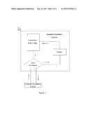
[0002] A circulating water system is of great significance to ensure normal operation of the engine in test. The conventional circulating water temperature control method is an open circulation method (i.e., the circulating water is driven by a water pump for the engine to flow out from the engine, exchanges heat and thereby is cooled in a radiator, and then returns to the engine), which is to say, the coolant is driven by a water pump for the engine to flow out from the engine, exchanges heat and thereby is cooled in a radiator, and then returns to the engine, as shown in FIG. 1. In the implementation process of the embodiments of the present invention, the inventor has found that the method in the prior art has at least the following problems. Though the method can attain the purpose of engine cooling control, it can't control the coolant pressure effectively; in addition, when the coolant temperature is near the 100° C. boiling point, a great deal of vapor will be produced in the engine and the coolant circulation loop, and can't be exhausted effectively. That condition is quite different to the actual condition of an engine operating in the vehicle, and can't be used to study and verify the actual cooling capability for the engine comprehensively. The test result can't truly meet the actual demand for engine test. For example, the engine coolant temperature control device disclosed in the Chinese Utility Model Patent No. 200620116208.0 titled as "Engine Coolant Temperature Control Device" has the above-mentioned problems.
SUMMARY OF THE INVENTION
[0003] The present invention provides a coolant temperature control system for engine performance test, to control the pressure of water flowing into/out of the engine in test and simulate the operating condition of the engine in a vehicle.
[0004] To attain the above-mentioned object, in an embodiments according to the present invention provides a coolant temperature control system for engine performance test, comprising an internal coolant circulation system, a heat exchange unit, a temperature monitoring and control unit, and an external coolant circulation system, wherein, the internal coolant circulation system and the external coolant circulation system are connected to the heat exchange unit respectively, and the internal coolant circulation system is connected to the engine; the temperature monitoring and control unit is connected to the internal coolant circulation system, the heat exchange unit, and the external coolant circulation system; wherein, the internal coolant circulation system is a closed internal circulation system provided with a pipeline for reducing the difference between water inlet pressure and water outlet pressure of the internal coolant circulation system.
[0005] In the coolant temperature control system described above, the closed internal circulation system comprises an engine water outlet pipe, an expansion water tank, a heat exchange pipe, an engine water inlet pipe, and a bypass unit, which are connected in sequence, wherein, the bypass unit comprises a bypass pipe and a bypass valve, the bypass valve is mounted on the bypass pipe, and the bypass pipe communicates the engine water inlet pipe with the engine water outlet pipe to reduce the difference between inlet pressure and outlet pressure of the internal coolant circulation system; the engine water outlet pipe is connected to the water outlet of the engine; the engine water inlet pipe is connected to the water inlet of the engine; the heat exchange pipe is connected to the heat exchange unit.
[0006] In the coolant temperature control system described above, the closed internal circulation system further comprises a vapor exhaust unit which comprises an extension pipe and a vapor exhaust pipe, wherein, one end of the extension pipe is connected to the top of the expansion water tank, and the other end of the extension pipe is provided with a valve; the vapor exhaust pipe connects a water channel in the cylinder head of the engine to the extension pipe.
[0007] In the coolant temperature control system described above, the temperature monitoring and control system comprises a temperature sensor and an electric temperature control box that are connected to each other, wherein, the temperature sensor is mounted on the engine water outlet pipe, and the electric temperature control box is connected to the heat exchange unit and the external coolant circulation system.
[0008] In the coolant temperature control system described above, the heat exchange unit is a plate-type heat exchanger.
[0009] In the coolant temperature control system, the heat exchanger pipe is further provided with a manual bleed valve and an automatic bleed valve.
[0010] In the coolant temperature control system, the engine water inlet pipe is further provided with a water replenishing valve.
[0011] In the coolant temperature control system described above, a coolant filter is further provided on the heat exchange pipe at the end near the expansion water tank.
[0012] In the coolant temperature control system described above, a regulating valve is provided at the joint between the heat exchange pipe and the engine water inlet pipe.
[0013] In the coolant temperature control system described above, a valve is provided at the joint between the engine water outlet pipe and the expansion water tank, and a valve is provided at the joint between the heat exchange pipe and the engine water inlet pipe.
[0014] The beneficial efficacies of the present invention lie in: a vapor exhaust pipe is added to the existing coolant temperature control system, and the vapor exhaust pipe connects the water channel in the cylinder head of the engine to an expansion water tank to ensure normal vapor exhaust of the circulating water channel in the engine; a bypass pipe and a bypass valve are mounted to the water inlet and water outlet of the engine to compensate the water inlet pressure with the water outlet pressure, so as to further reduce the difference between water inlet pressure and water outlet pressure and increase water inflow rate and water outflow rate; thus, the system provided in the present invention attain the purpose of simulating the actual operating condition of engine in the vehicle for the cooling water system in the engine test, can keep the engine operating stably at 100° C. boiling point, and can increase the water inlet pressure by 20-50 kPa in the test.
[0015] Hereunder the present invention will be detailed in embodiments, with reference to the accompanying drawings; however, the present invention is not limited to the embodiments and drawings.
BRIEF DESCRIPTION OF THE DRAWINGS
[0016] FIG. 1 is a schematic diagram of the coolant temperature control system in the prior art;
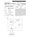
[0017] FIG. 2 is a schematic diagram of the coolant temperature control system according to an embodiment of the present invention;
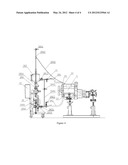
[0018] FIG. 3 is a schematic diagram showing the working principle of the coolant temperature control system according to an embodiment of the present invention;
[0019] FIG. 4 is a schematic diagram showing the structure of the coolant temperature control system according to an embodiment of the present invention.
[0020] Wherein, the symbols in the drawings are:
[0021] 1. Engine [0022] 11. Water outlet [0023] 12. Water inlet [0024] 13. Water channel in cylinder head
[0025] 2. Internal coolant circulation system [0026] 20. Closed internal circulation system [0027] 201. Engine water outlet pipe [0028] 2011. Valve I [0029] 202. Engine water inlet pipe [0030] 2021. Valve II [0031] 2022. Water replenishing valve [0032] 203. Heat exchange pipe [0033] 2031. Automatic bleed valve [0034] 2032. Manual bleed valve [0035] 2033. Regulating valve [0036] 2034, 2035 Coolant filter [0037] 204. Bypass unit [0038] 2041. Bypass valve [0039] 2042. Bypass pipe [0040] 205. Vapor exhaust unit [0041] 2051. Valve [0042] 2052. Extension pipe [0043] 2053. Vapor exhaust pipe [0044] 207. Expansion water tank [0045] 2071. Pressure limiting valve [0046] 2072. Pressure meter [0047] 21. Open internal circulation system
[0048] 3. Heat exchange unit [0049] 31. Plate-type heat exchanger
[0050] 4. Temperature monitoring and control unit [0051] 41. Temperature sensor [0052] 42. Electric temperature control box
[0053] 5. External coolant circulation system
DETAILED DESCRIPTION OF THE EMBODIMENTS
[0054] Hereunder the structure and working principle of the device provided in an embodiment of the present invention will be detailed, with reference to the accompanying drawings.
[0055] The coolant described in the embodiment of the present invention can be water or any other coolant; in the embodiment of the present invention, water or a coolant is employed in the internal circulation system, while water is employed in the external circulation system; however, the present invention is not limited to these. In the embodiment of the present invention, the external circulation system is a known technique in the prior art, and therefore will not be detailed here. Hereunder the internal circulation system in the embodiment of the present invention will be detailed.
[0056] In engine tests, test control has to be exercised often by simulating the actual operating condition of engine in a vehicle and applying a variety of complex test conditions. The control of circulating water for engine is of great significance in an engine test, and is a decisive factor for normal test and operation of the engine. The conventional circulating water temperature control method is an open circulation method (i.e., the circulating water is driven by a water pump for the engine to flow out from the engine, exchanges heat and thereby is cooled in a radiator, and then returns to the engine). FIG. 1 is a schematic diagram of the coolant temperature control system in the prior art. As shown in FIG. 1, the internal coolant circulation system is an open internal circulation system 21. Though the conventional method can effectively control the circulating water temperature for the engine, the condition is quite different from the actual operating condition of the engine in a vehicle; in addition, the water inflow pressure can't be controlled effectively, and the test result can't truly show the actual demand for engine test. In the embodiment of the present invention, a simple coolant temperature control system, which can control the water inflow pressure and outflow pressure of engine and simulate the actual operating condition of engine in a vehicle, is designed, incorporating different test conditions for engine test. Please see FIGS. 2, 3, and 4, wherein, FIG. 2 is a schematic diagram of the coolant temperature control system provided in an embodiment of the present invention, FIG. 3 is a schematic diagram showing the working principle of the coolant temperature control system in an embodiment of the present invention, and FIG. 4 is a schematic diagram showing the structure of the coolant temperature control system provided in an embodiment of the present invention. The coolant temperature control system for engine performance test provided in the embodiment of the present invention comprises an internal coolant circulation system 2, a heat exchange unit 3, a temperature monitoring and control unit 4, and an external coolant circulation system 5, wherein, the internal coolant circulation system 2 and the external coolant circulation system 5 are connected to the heat exchange unit 3 respectively; the internal coolant circulation system 2 is connected to the engine 1; the temperature monitoring and control unit 4 is connected to the internal coolant circulation system 2, the heat exchange unit 3, and the external coolant circulation system 5; the internal coolant circulation system 2 is a closed internal circulation system 20, with a bypass unit 204 mounted between an engine water inlet pipe 202 and an engine water outlet pipe 201, the bypass unit 204 communicates with the engine water inlet pipe 202 and the engine water outlet pipe 201, so that the internal coolant circulation system for the engine forms a closed system, and the water inlet pressure is compensated by the water outlet pressure via the bypass unit 204; thus, the difference between water inlet pressure and water outlet pressure is reduced, and water inflow rate and water outflow rate are increased. In the embodiment, the internal coolant circulation system 2 comprises an engine water outlet pipe 201, an expansion water tank 207, a heat exchange pipe 203, an engine water inlet pipe 202, and a bypass pipe 2042 and a bypass valve 2041, which are connected in sequence, wherein, the engine water outlet pipe 201 is connected to the water outlet 11 of the engine 1, the engine water inlet pipe 202 is connected to the water inlet 12 of the engine 1, the bypass valve 2041 is mounted on the bypass pipe 2042, the bypass pipe 2042 communicates with the engine water inlet pipe 202 and the engine water outlet pipe 201, and the heat exchange pipe 203 is connected to the heat exchange unit 3. A water replenishing valve 2022 is mounted on the engine water inlet pipe 202. If water for the engine is used as the coolant, the water replenishing valve 2022 can be opened when required, so that the engine water inlet pipe 202 communicates with the external coolant circulation system 5 and thereby the closed internal circulation system 20 can be replenished with the circulating water in the external coolant circulation system 5. The engine water outlet pipe 201 connects the engine water outlet 11 to the expansion water tank 207, and a valve I 2011 is mounted at the joint between the engine water outlet pipe 201 and the expansion water tank 207; the heat exchange pipe 203 connects the expansion water tank 207 to the engine water inlet pipe 202, and a valve II 2021 is mounted at the joint between the heat exchange pipe 203 and the engine water inlet pipe 202; a coolant filter 2034 is mounted on the heat exchange pipe 203 at an end near the expansion water tank 207; a regulating valve 2033 is mounted at the joint between the heat exchange pipe 203 and the engine water inlet pipe 202, and the regulating valve 2033 is connected with the engine water inlet pipe 202, the heat exchange pipe 203, and the heat exchange unit 3 respectively; a coolant filter 2035 is mounted on the pipeline via which the regulating valve 2033 is connected to the external coolant circulation system 5, so as to filter the coolant that flows from the external coolant circulation system 5 into the heat exchange unit 3; in this embodiment, the heat exchange unit 3 is a plate-type heat exchanger 31; an automatic bleed valve 2032 and a manual bleed valve 2031 are mounted on the pipeline via which the regulating valve 2033 is connected to the plate-type heat exchanger 31. The engine water inlet pipe 202 is communicated with the engine water outlet pipe 201 through the bypass pipe 2042 with the bypass valve 2041; the bypass pipe 2042 is arranged at the side near the heat exchange pipe 203, and the compensatory pressure of water outflow for water inflow is controlled by regulating the valve opening of the bypass valve 2041, so as to reduce the difference between water inlet pressure and water outlet pressure. The closed internal circulation system 20 further comprises a vapor exhaust unit 205, which comprises an extension pipe 2052 and an vapor exhaust pipe 2053, wherein, the extension pipe 2052 is connected at one end thereof to the top of the expansion water tank 207 and is provided with a valve 2051 on the terminal thereof, and the valve 2051 is in normally closed state during normal operation; the vapor exhaust pipe 2053 connects the water channel 13 in the cylinder head of the engine 1 to the extension pipe 2052 on the expansion water tank 207 in a way that the end of the vapor exhaust pipe 2053 connected to the extension pipe 2052 is higher than the other end of the vapor exhaust pipe 2053 connected to the water channel 13 in the cylinder head of the engine 1 and the vapor exhaust pipe 2053 is not in bent state. Vapor is produced as the water temperature rises up during operation of the engine, and the vapor is exhausted through the vapor exhaust pipe 2053 to the expansion water tank 207. Once a pressure meter 2072 detects the pressure in the expansion water tank 207 is higher than a set value, a pressure limiting valve 2071 will be opened to regulate the pressure. In this embodiment, the heat exchange unit 3 is a plate-type heat exchanger 31. The temperature monitoring and control system 4 comprises a temperature sensor 41 and an electric temperature control box 42 that are connected to each other, wherein, the temperature sensor 41 is mounted at the engine water outlet 21, and is used to monitor the temperature of the circulating coolant and transmit the temperature signal to the electric temperature control box 42; the temperature control box 42 are connected to the heat exchange unit 3, external coolant circulation system 5, and a control system (not shown), respectively.
[0057] In summary, in the embodiments of the present invention, a vapor exhaust pipe is added to the existing coolant temperature control system, and the vapor exhaust pipe connects the water channel in the cylinder head of the engine to an expansion water tank to ensure normal vapor exhaust of the circulating water channel in the engine; a bypass pipe and a bypass valve are mounted to the water inlet and water outlet of the engine to compensate the water inlet pressure with the water outlet pressure, so as to further reduce the difference between water inlet pressure and water outlet pressure and increase water inflow rate and water outflow rate; thus, the system provided in the present invention attains the purpose of simulating the actual operating condition of engine in the vehicle for the cooling water system in the engine test. The system provided in the invention can keep the engine operating stably at 100° C. boiling point, and can increase the water inlet pressure by 20˜50 kPa.
[0058] Of course, many other embodiments can be implemented on the basis of the present invention. Those skilled in the art can make various modifications and variations to the embodiments, without departing from the spirit of the present invention. However, these modifications and variations shall fall into the protected scope of the present invention as confined by the claims.
User Contributions:
Comment about this patent or add new information about this topic:
Images included with this patent application:
 |  |
 |  |
 |
| Similar patent applications: | |
| Date | Title |
|---|---|
| 2011-05-05 | Geosolar temperature control construction and method thereof |
| 2009-03-19 | Cooling system for high power vacuum tubes |
| 2012-10-11 | Temperature controller for unit |
| 2008-11-27 | Constant temperature controller |
| 2009-07-23 | Thermal control unit for semiconductor testing |
| New patent applications in this class: | |
| Date | Title |
|---|---|
| 2018-01-25 | System and method for managing transmission fluid temperature |
| 2017-08-17 | Gas turbine engine component having vascular engineered lattice structure |
| 2016-09-01 | Cooling system in a vehicle |
| 2016-09-01 | Vehicle heating device |
| 2016-07-14 | System for cooling hybrid vehicle electronics, method for cooling hybrid vehicle electronics |
| New patent applications from these inventors: | |
| Date | Title |
|---|---|
| 2022-09-15 | Antenna adjustment method and apparatus, gateway, terminal, adjustment system, and storage medium |
| 2022-09-08 | Method and apparatus for generating electronic map, electronic device and storage medium |
| 2022-09-08 | Bonding fixture and bonding device with the same |
| 2022-07-07 | Kras mutant protein inhibitors |
| 2022-03-31 | Method for displaying media resources and terminal |
| Top Inventors for class "Heat exchange" | |
| Rank | Inventor's name |
|---|---|
| 1 | Levi A. Campbell |
| 2 | Chun-Chi Chen |
| 3 | Tai-Her Yang |
| 4 | Robert E. Simons |
| 5 | Richard C. Chu |