Patent application title: Travel easy adjustable deck
Inventors:
Joseph P. Rowell (Van Alstyne, TX, US)
Kristina A. Rowell (Van Alstyne, TX, US)
IPC8 Class: AE01D1512FI
USPC Class:
14 24
Class name: Bridges transportable
Publication date: 2012-04-26
Patent application number: 20120096655
Abstract:
This invention is intended for use in outdoor activities where a firm,
continuous, strong, and maintenance free walking surface that overcomes
obstacles such as wetness, mud, rocks, and uneven terrains with
simple-to-expand, light-weight, and easily transported attributes is
desired.Claims:
1. A foot/leg assembly which provides a range of adjustment that
overcomes common outdoor terrain found in areas of natural erosion often
encountered in campgrounds, backyards or garden settings. This range of
adjustment provides an escape from runoff and promotes an easier, even
walking surface over topographic dips, cracks, rocks, and mounds.
2. The adjustable foot/leg assembly is a sturdy, no-tool required, connection between multiple decking sections.
3. Ease of deck expansion is limited only by the area in which the deck is placed and can be easily and quickly accomplished without the required use of special tools or excessive strength.
4. Multiple placement options of deck sections allow for final deck design to be created according to personal preference and/or event/venue needs.
5. The overall portability of the decking unit itself allows for minimal space requirements in travel vehicles as well as overall weight considerations that can be easily customized according to the individual travelers' preferences and/or needs.
6. Because of low ground clearance, accessibility by wheel-chair, walker, or other encumbered individuals can be achieved without the need of ramps or stairs.
7. The deck is robust, heat resistant, and maintenance free.
8. The open mesh design reduces the amount of mud, dust, grass, and other debris carried inside the living space as well as providing quick and easy visibility of any objects underneath deck.
Description:
BACKGROUND OF INVENTION:
[0001] Several issues exist with previously designed portable decks. Some are strictly to raise one to door level of a trailer or RV with room enough to turn around (Greenwood, Aug. 4, 1972 U.S. Pat. No. 3,808,757; Weaver, Sep. 7, 1982, U.S. Pat. No. 4,347,638; Anstead, May 31, 1988 U.S. Pat. No. 4,747,243) and require guardrails (Wyse, Jul. 26, 1988, U.S. Pat. No. 4,759,162; Carson, Apr. 8, 2008, U.S. Pat. No. 7,353,639 B2) or stairs to reach the deck level (Wagner, III, Jul. 8, 1986 U.S. Pat. No. 4,598,510). Others are just plain difficult to assemble (Cauceglia et al, Dec. 9, 1975, U.S. Pat. No. 3,924,370; Rebentisch et al, Jul. 14, 1981, U.S. Pat. No. 4,277,923), requiring tools, brawn, and multiple persons. Other designs (Weaver, Mar. 16, 1993, U.S. Pat. No. 5,193,878; Baumgartner et al, May 23, 1995, U.S. Pat. No. 5,417,468; Johnson, May 18, 2004 U.S. Pat. No. 6,736,446 B1) have been physically mounted to a vehicle which, although technically portable, makes the deck usable only when the vehicle can access the area where the deck is needed. A majority of the decks are not light-weight enough for a single individual to carry. Nor are they transportable in a vehicle (with the exception of the mounted deck) where limited storage space and added towing weight must be considered.
[0002] Some of these previous designs have not accounted for variation in terrain, use in multiple locations and have restricted themselves to a specific size.
[0003] Therefore, the principal objectives of the present invention is to provide a deck system which is sturdy, light-weight, small enough to be transportable yet large enough to be practically functional, easily assembled and disassembled, high enough to rise above rain levels yet not so high as to require stairs or a ramp system to use, and flexible enough to adjust to fluctuations in topography while providing a sturdy, even walking surface.
BRIEF SUMMARY OF INVENTION
[0004] The submitted invention is for a devise where a flat, constant walking surface is desired without restrictions of permanency. This invention allows flexibility in location, overall deck size while allowing for variance in height. It is light-weight and compact enough to be portable, easily stored and packed for travel.
BRIEF DESCRIPTION OF DRAWINGS
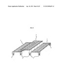
[0005] FIG A illustrates the top perspective of the deck in disassembled form.
[0006] FIG B illustrates the top view of the assembled deck panel with the cross beam shadowed.
[0007] FIG C illustrates the underneath perspective of the deck in disassembled form
[0008] FIG D illustrates the assembled view of the underneath of the deck panel.
[0009] FIG E illustrates the side perspective of the foot portion of the foot/leg bracket assembly.
[0010] FIG F illustrates the top view of the foot/leg bracket assembly
[0011] FIG G illustrates the one completely assembled decking section.
[0012] FIG H illustrates an expanded deck of three sections and the connection points.
DETAILED DESCRIPTION OF INVENTION
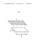
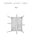
[0013] Beginning with FIG A, the top perspective of the decking section in disassembled form, item
[0014] is 4''×8''×11/2'' expandable iron or aluminum that is welded to the top of the deck frame making a sturdy deck top. [2] is a L-angle iron or aluminum 1''×1''×1/8'', welded into the form of a 2'×4' rectangular deck frame. For increased stability, a support bar is added. The support bar [3] is another L-angle beam of the 1''×1''×1/8'' size welded length wise to the middle points of the 2' frame sides.
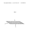
[0015] FIG B depicts the assembled deck section. Again, [1] is the 4''×8''×11/2'' expanded metal deck top and [2] is the 1''×1''×1/8'' frame with the dashed detail of [3] indicating the 1''×1''×1/8'' support beam.
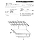
[0016] FIG C shows the bottom side of the unassembled deck section. [1] Is the 4''×8''×11/2'' expanded metal or aluminum mesh deck top. [2] Is the L-angle iron or aluminum 1''×1''×1/8'' deck frame. [3] Is the added support crossbeam made of 1''×1''×1/8'' angle iron or aluminum. While [4] indicates the position of the 11/4'' square leg receptacles.
[0017] FIG D represents the underneath view of the assembled decking plane. [1] Are the 11/4'' leg receptacles, [2] is the 1''×1''×1/8'' angle iron or aluminum decking frame, [3] is 4''×8''×11/2'' expandable iron or aluminum decking mesh and [4] is the location of the 1''×1''×1/8'' support beam.
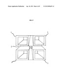
[0018] FIG E shows the foot/leg bracket assembly. [1] Indicates the individual leg that inserts into the 11/4'' receptacles located underneath the deck. There are four (4) separate legs per foot/leg bracket. Each leg is 1'' square making for a snuck fit into the 11/4'' leg receptacles found underneath the deck corners. These four legs on the assembly enable up to four separate decking sections to be joined together securely and without unevenness or gaps between deck sections. If deck expansion is not desired or only two or three additional decking sections are preferred the foot can be rotated to safely hide the other leg to avoid possibility of injury. Item [2] is the stabilizing foot and [3] is the adjustment bolt allowing for a variation of decking height. This height adjustment can be executed by either turning manually or by the adjustment nut (shown in FIG) which is accessible through the top of the decking unit.
[0019] FIG F shows the top view of the foot/leg bracket assembly. Item [1] depicts the top view looking down upon the individual leg units with Item [2] highlighting the top-side adjustment nut.
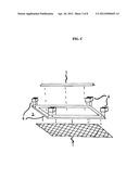
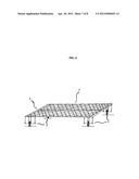
[0020] FIG G illustrates the assembled decking unit [1] being the complete deck section and [2] indicating the position of the foot/leg assembly when installed and [3] highlighting the crossbeam running length wise underneath the deck top.
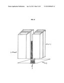
[0021] FIG H represents the foot/leg bracket position when connecting two or more deck sections together. [1] are the deck sections already positioned with leg assembly attached. [2] indicates the position of the foot/leg bracket when adding a section. Notice that the assembly is rotated so that half the leg assembly protrudes away from the first deck section allowing access to a connecting leg for decking section [4]. Item [3] depicts the position of the foot assembly when not being used as a connector and, therefore, is turned in to hide under the deck top. [4] is a deck top being lowered onto the awaiting leg connectors already in place under the outside positioned deck sections.
[0022] Although the preferred embodiment has been described in detail, it should be understood that various changes, substitutions and alterations can be made therein without departing from the spirit and scope of the invention as defined by the appended claims.
User Contributions:
Comment about this patent or add new information about this topic:
Images included with this patent application:
 |  |
 |  |
 |  |
 |  |
 |
| Similar patent applications: | |
| Date | Title |
|---|---|
| 2013-08-22 | Vessel, a motion platform, a control system, a method for compensating motions of a vessel and a computer program product |
| New patent applications in this class: | |
| Date | Title |
|---|---|
| 2016-06-09 | Light-weight temporary bridge system and building method thereof |
| 2016-06-02 | Apparatus to interface a boarding bridge and a low doorsill airplane |
| 2016-05-19 | Portable heated ramp and method |
| 2016-01-07 | Bridge adapted for accessing an aircraft compartment via a manhole |
| 2015-12-10 | Vehicle for transporting elongate objects |
| Top Inventors for class "Bridges" | |
| Rank | Inventor's name |
|---|---|
| 1 | David Johnson |
| 2 | Robert W. Honeycutt |
| 3 | Donald Morris |
| 4 | Matthew Sveum |
| 5 | Alan Cohn |