Patent application title: Earthquake Proof Wall Panels
Inventors:
Teow Beng Hur (Klang, MY)
Assignees:
HC Precast System Sdn. Bhd.
IPC8 Class: AE04H902FI
USPC Class:
52 7911
Class name: Preassembled subenclosure or substructure section(s) of unit or building with retaining or attaching means cast in situ
Publication date: 2012-01-26
Patent application number: 20120017520
Abstract:
A building structure is formed of large, pre-formed or pre-cast
structural slabs i.e., pre-cast wall panels (1) that contain a plurality
of horizontally extending reinforcing members (2) that protrude out of
the wall panel at its two opposite ends by a predetermined length. The
pre-cast wall panel (1) further consists of a plurality of recesses (3)
and projecting recess keys (4). The pre-cast wall panels (1) are placed
facing each other or orthogonal to each other each such that when an
imaginary line from the ends of the wall panels that are oriented towards
each other, projects from the projecting reinforcing members (2), of each
respective reinforced concrete pre-cast wall panel (1), these lines
intersect at a common point. The gap in between the wall panels provides
a means of connecting the individual pre-cast wall panels by means of a
wet joint (11a, 11b, 11c, 11d). The wet joints (11b, 11c, 11d) can then
act as columns 5 of a building structure. The construction of the
pre-cast wall panels (1) consisting of a plurality of recesses (3) and
recess key projections (4) together with the reinforcing members (2)
serve to provide structural stability and robustness to the building
structure. The recesses (3), recess key projections (4) in addition to
the extending reinforcing members (2) more particularly serve to transfer
the loads of the pre-cast wall panels (1) directly to the columns (5) of
a building structure.Claims:
1. A reinforced concrete pre-cast wall panel (1) which forms partition
compartments of a building, that are further designed as structural
elements to be integrated with a cast in situ building structure frame
wherein the reinforced concrete pre-cast wall panels that is capable of
increasing the stability and robustness of a building structure at a low
cost and hence provide a measure of earth-quake proofing apart from
enabling a building structure to be built using a modular approach and
allowing said building to be built in a quick and efficient manner;
characterized in that said pre-cast wall panel has a plurality of
recesses (3) and recess key projections (4) that are alternately
staggered and further distributed along its entire vertical length at
both its opposing sides, thereby aiding said wall panels in transferring
their loads to the columns of the building structure and thus providing
for the structural stability and robustness of the building structure.
2. A reinforced concrete pre-cast wall panel as in claim 1, wherein said pre-cast wall panel contains a plurality of vertically equidistant reinforcing members (2) extending laterally through the entire width of said pre-cast wall panel and further protruding at both ends by a pre-defined length.
3. A reinforced concrete pre-cast wall panel as in claim 2, wherein the reinforcing members (2) protrude or extend outwards from the centre of the said recesses at both the opposing sides of said reinforced concrete pre-cast wall panel.
4. A reinforced concrete pre-cast wall panel as in claim 1, wherein said pre-cast wall panels are used as structural elements to be integrated with a cast in situ building structure characterized in that two identical adjoining wall panels (1) are joined together side by side to form a space that is filled with concrete thus forming a wet joint (11a).
5. A reinforced concrete pre-cast wall panel (1) as in claim 1, wherein said pre-cast wall panels are used as structural elements to be integrated with a cast in situ building structure characterized in that two identical wall panels (1) are joined together at the sides to a form a space that is filled with concrete forming a "L:" shaped wet joint (11d) that can act as a column (5) of a building structure.
6. A reinforced concrete pre-cast wall panel as in claim 1, wherein said pre-cast wall panels are used as structural elements to be integrated with a cast I situ building structure characterized in that three identical wall panels (1) are joined together to form a space that is filled with concrete forming a "T" shaped wet joint (11b) that can act as a column (5) of a building structure.
7. A reinforced concrete pre-cast wall panel as in claim 1, wherein said pre-cast wall panels are used as structural elements to be integrated with a cast in situ building structure characterized in that four identical wall panels (1) are joined together to form a space that is filled with concrete forming a "X" shaped wet joint (11d) that can act as a column (5) of a building structure.
8. A structural unit for a building comprising a reinforced concrete pre-cast wall panel as defined in claim 1.
9. A structural unit according to claim 8, further integrated with lateral beams (8, 9), floor slabs (7) and bedding structures (10), wherein the reinforced concrete pre-cast wall-panels (1) are erected into box compartment modules with formworks bolted into position for the subsequent casting of in situ columns (5).
Description:
[0001] The present invention relates to the field of earth-quake proof
construction methods, more particularly the present invention relates to
reinforced concrete pre-cast wall panels that form a structural element
of a building structure and consequently enables the design and build of
a building using a modular approach.
BACKGROUND TO THE INVENTION
[0002] It is impossible to make a building one-hundred percent earthquake proof. In the very strongest earthquake, even the best engineered building will suffer severe damage. However, engineers do their best to make sure the building will stand up long enough for the occupants to get out to safety.
[0003] From a simplistic standpoint, an earthquake places a sideways load on a building. Therefore, in addition to making a building (or bridge or any other structure) capable of holding up forces from gravity caused by the weight of the structure and its contents, an earthquake resistant structure can withstand a considerable sideways force. This is done by tying the walls, floor, roof, and foundations into a rigid box.
[0004] The worst buildings, from an earthquake standpoint, are made of un-reinforced masonry such as brick or concrete blocks. Generally, the walls are made of bricks stacked on top of each other and held with mortar. The roof is then made of beams of wood or steel laid across the top of the wall. The roofs weight is carried straight down through the wall to the foundations. When this type of building gets a sideways jolt, the masonry walls tip over or crumble and the roof falls in on the unfortunate occupants like a house of cards. Since this type of structure is prevalent in poorer countries, the death toll from earthquakes can be many, many times higher than in places with strict building codes, such as Japan and California.
[0005] There are various approaches to make a building earthquake proof. One possibility exists to build energy dissipation zones within a building structure to dissipate the energy registered by a building structure.
[0006] Among the many strategies employed in the constructions of buildings and homes to ensure that these structures are somewhat earthquake proof, is the use of reinforced concrete in which steel reinforced bars (re-bars) have been incorporated to strengthen concrete structures that would otherwise be brittle.
[0007] Concrete is reinforced to give it extra tensile strength; without reinforcement, many concrete buildings would not have been possible. Reinforced concrete can be classified as precast or cast in-situ concrete. It can further encompass many types of structures and components, including slabs, walls, beams, columns, foundations, frames and more.
[0008] A construction system where steel reinforcement is embedded in the mortar joints of masonry or placed in holes and after being filled with concrete or grout is called reinforced masonry. The devastating 1933 Long Beach earthquake revealed that masonry construction should be improved immediately. Then, the California State Code made the reinforced masonry mandatory.
[0009] There are various practices and techniques to achieve reinforced masonry. The most common type is the reinforced hollow unit masonry. The effectiveness of both vertical and horizontal reinforcement strongly depends on the type and quality of the masonry, i.e. masonry units and mortar.
[0010] To achieve a ductile behavior of masonry, it is necessary that the shear strength of the wall be greater than the tensile strength of reinforcement to ensure a kind of bending failure.
[0011] The present invention relates to the field of reinforced concrete pre-cast wall panels that enable a building structure to be somewhat earthquake proof. The pre-cast wall panels of the present invention, apart from being reinforced with reinforcing members and hence providing a certain measure of tensile strength to the wall panel is aimed to be used in conjunction with other structural elements of a building structure to enable a modular design and build of a building structure.
SUMMARY OF THE INVENTION
[0012] It is an object of the present invention, to provide a structural element to integrate with cast in situ building structure frames, thus enabling a building structure to be built using a modular approach.
[0013] It is another object of the present invention, to provide a pre-cast reinforced concrete wall panel that enables the construction of a structurally stable and robust building structure efficiently at a low cost and low construction time.
[0014] It is further an object of the present invention, to provide a pre-cast wall panel structural element that has a plurality of vertically equidistant reinforcing members extending laterally through the entire width of said pre-cast wall panel and further protruding at both ends by a pre-defined length that is dictated by any of a number of building construction standards.
[0015] It is still another object of the present invention, to provide a pre-cast wall panel structural element that has a plurality of recesses and recess key projections that are alternately staggered and further distributed along the entire length of said wall panel.
[0016] It is yet another object of the present invention, to provide a pre-cast wall panel structure that represents a structural element of a building construction that eliminates the necessity of pre-casting a building column to be integrated into the building frame.
[0017] It is yet another object of the present invention, to provide a pre-cast wall panel structure that is able to transfer and hence distribute evenly, the vertical load imposed on the overall building structure by its own weight to the respective columns of the building thereby providing for the structural stability and robustness of the building structure.
[0018] Accordingly, the present invention provides a reinforced pre-cast wall panel that allows a building structure to withstand earthquake tremors. The pre-cast wall panel of the present invention apart from being reinforced with reinforcing members is provided with a plurality of recesses and recess key projections staggered at alternate intervals along the entire vertical length of the pre-cast wall panel of the present invention. These, plurality of recesses and projections in addition to the reinforcing members, aid the pre-cast wall panels in transferring their loads to the columns of the building structure and thus providing for the structural stability and robustness of the building structure.
BRIEF DESCRIPTION OF THE DRAWINGS
[0019] The invention will now be described in greater detail, by way of example, with reference to the drawings, in which:
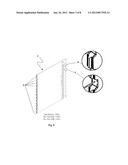
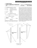
[0020] FIG. 1 is a diagram illustrating the manner in which a wet-joint is formed between two adjacent reinforced pre-cast wall panels with a similar arrangement of a plurality of recesses and recess key projections;
[0021] FIG. 2 is a diagram illustrating the manner in which a wet-joint is formed between three reinforced pre-cast wall panels with a plurality of similarly lined recesses and recess key projections;
[0022] FIG. 3 is a diagram illustrating the manner in which a wet joint is formed between four reinforced pre-cast wall panels with a plurality of similarly lined recesses and recess key projections;
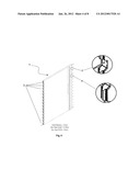
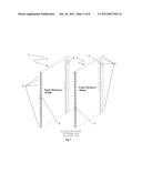
[0023] FIG. 4 is a diagram illustrating the manner in which a wet joint is formed between two pre-cast wall panels with a plurality of similarly arranged recesses and recess key projections, when the respective wall panels are orthogonal to each other;
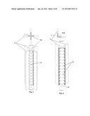
[0024] FIG. 5 is a diagram illustrating a single pre-cast wall panel of the present invention with a plurality of recesses and recess key projections with a panel thickness of 100 millimeters, a height of 3 meters and a width of 6 meters;
[0025] FIG. 6 is a diagram illustrating a single pre-cast wall panel of the present invention with a plurality of recesses and recess key projections with a panel thickness of 120 millimeters, a height of 4.5 meters and a width of 6 meters;
[0026] FIG. 7 is a diagram illustrating a pair of pre-cast wall panels of the present invention with a plurality of recesses and recess key projections with a panel thickness of 150 millimeters and 160 millimeters respectively and a height and width of 6 meters;
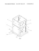
[0027] FIG. 8 is a diagram illustrating a two story building structure utilizing the pre-cast wall panels of the present invention;
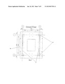
[0028] FIG. 9 is a diagram illustrating the plan view of the ground floor of the two story building structure of FIG. 8; and
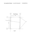
[0029] FIG. 10 is a diagram illustrating the plan view of the first floor of the two story building structure of FIG. 8.
DETAILED DESCRIPTION OF THE INVENTION
[0030] With reference to FIGS. 1 to 10, the reinforced concrete pre-cast wall panel 1 of the present invention will now be described in detail. More particularly the reinforced concrete pre-cast wall panel 1 of the present invention will be described with reference to FIGS. 5 to 7 and subsequently the manner in which said wall panels 1 are joined to one another will be described with reference to FIGS. 1 to 4. Finally, the manner in which the reinforced concrete pre-cast wall panels 1 of the present invention 1 is used as a structural element that is integrated with a cast in situ building frame structure is described with reference to FIGS. 8 through 10.
[0031] Referring to FIGS. 5 to 7, the reinforced concrete pre-cast wall panel 1 of the present invention has a plurality of recesses 3 and recess key projections 4 that are alternately staggered and are further arranged along the entire vertical length of both the opposing sides of said wall panel 1. In addition to the plurality of recesses 3 and recess key projections 4, said wall panel 1 is further reinforced with a plurality of reinforcing members 2. These plurality of reinforcing members 2, are embedded within the concrete slab of the reinforced concrete pre-cast wall panel 1 of the present invention and further oriented laterally extending to and protruding out by a predetermined length that is dictated by any number of building construction standards at both the opposing ends of said wall panel 1. The plurality of reinforcing members 2 are spaced at equidistant intervals of length across the entire vertical length of the wall panel 1. The said plurality of reinforcing members 2 protruding out of the reinforced concrete pre-cast wall panel 1 at both the opposing ends of said wall panel 1, protrude or extend outwards from the centre of the plurality of said recesses 3.
[0032] This plurality of recesses 3 and recess key projections 4, are formed such that each individual recess 3 of the plurality of recesses 3 appear to be in the shape of an inverted trapezoid and the corresponding recess key projections 4 on the other hand appear to be in the shape of a trapezoid, i.e. the form of the recesses 3 and recess key projections 4 are formed such that they appear to have shapes that are complementary to each other.
[0033] The plurality of recesses 3 and recess key projections 4 in addition to afore mentioned reinforcing members 2 serve to aid said wall panels 1 in transferring and hence distributing evenly, the vertical load imposed on the overall building structure by its own weight to the respective columns 5 of the building thereby providing for the structural stability and robustness of the building structure.
[0034] The reinforced concrete pre-cast wall panels 1 of the present invention form a structural element of a building structure wherein said precast wall panels 1 are integrated into the building structure frame to thus enable the design and building of a building structure using a modular approach. This modular approach to design and building enables building structures to be built in a time effective, cost efficient and labor efficient manner.
[0035] Referring to FIGS. 1 to 4, the manner in which the reinforced concrete pre-cast wall panels 1 of the present invention are attached to one another will now be described. The wall panels 1 of the present invention can be aligned in one of four possible configurations, in other words, one wall panel 1 of the present invention can be attached to a maximum of up to three other similar wall panels 1. In all four possible configurations of wall panels 1, each wall panel 1 is placed facing each other, orthogonal to each other or a combination of both the afore mentioned configurations, such that when an imaginary line from the ends of the wall panels 1 that are oriented towards each other, projects from the projecting reinforcing members 2, of each of the respective reinforced concrete pre-cast wall panels 1, these lines intersect at a common point, therein a space is formed wherein this space is filled with concrete with the aid of appropriately formed formworks to thus create a wet joint 11a, 11b, 11c, 11d that can act as a column 5 of a building structure. It is thus a realization of an object of the present invention to provide a pre-cast wall panel 1 structure that represents a structural element of a building construction that eliminates the necessity of pre-casting a building column 5 of a building structure. It is thus a realization of an object the present invention to provide a pre-cast wall panel structure that represents a structural element of a building construction that eliminates the necessity of pre-casting a building column to be integrated into the building frame.
[0036] FIG. 1, illustrates two pre-cast wall panels 1 of the present invention, that are joined together, side by side to form a space filled with concrete thus forming a wet joint 11a. More particularly, with reference to said figure, one individual wall panel 1 is joined with another identical adjacent wall panel 1 wherein each of the wall panels 1 are facing each other on the sides, such that the distance between the two wall panels 1 is slightly greater by a predetermined miniscule length than the sum of the individual lengths of the two projecting reinforcing members 2, thus forming a space that is filled with concrete with the aid of formwork to create a wet joint 11a.
[0037] FIG. 2, illustrates two pre-cast wall panels 1, of the present invention, that are joined together at the sides to form a space that is filled with concrete forming a "L" shaped wet joint 11c when viewed from the top. More particularly, with reference to said figure, a first wall panel 1 is joined together with a second wall panel 1 wherein the sides of each of the wall panels are orthogonal to each other, such that when an imaginary line from the side ends of the wall panels 1 that are oriented towards each other projects from the projecting members 2, of each of the respective reinforced concrete pre-cast wall panels 1, these lines intersect at a common point, thus forming a space that is filled with concrete with the aid of formwork to create an "L" shaped wet-joint 11c when viewed from the top.
[0038] FIG. 3 illustrates three pre-cast wall panels 1 of the present invention, that are joined together at the sides to form a space that is filled with concrete forming a "T" shaped wet joint 11b when viewed from the top. More particularly with reference to said figure, a first wall panel 1 is joined with a second and third wall panel 1 respectively, wherein one side of the first wall panel 1 is disposed facing one of the third wall panel 1, such that when an imaginary line that projects from the ends of the projecting reinforcing members 2 of the first and second wall panel 1, with sides that are respectively oriented towards each other, these lines meet at a point in space and intersect with a third imaginary line that projects from the reinforcing members 2 of the side of the third wall panel 1 that is oriented towards the Cartesian plane formed by the other two wall panels 1 with sides facing each other in opposition, thus forming a space that is filled with concrete with the aid of formwork to create a "T" shaped wet joint 11b when viewed from the top.
[0039] FIG. 4 illustrates four pre-cast wall panels 1 of the present invention, that are joined together at the sides to form a space that is filled with concrete thus forming an "X" shaped wet-joint 11d when viewed from the top. More particularly, with reference to said figure, a first wall panel is joined with three other wall panels 1, i.e. a second, a third and fourth wall panel 1 wherein one side of a first wall panel 1 is disposed facing one other side of a second wall panel 1 and similarly one side of a third wall panel 1 is disposed facing one other side of a fourth wall panel 1. The pair of the first and second wall panels 1 are, oriented facing each other such that an imaginary line projects from the opposing ends of each said wall panel 1, these lines too meet at a common point in space. The said pairs of the first and second wall panels 1 together with the third and fourth wall panel 1 are respectively oriented such that they form Cartesian planes that are orthogonal to each other, such that when an imaginary line from the ends of the wall panel 1 that are oriented towards each other, projects from the projecting members 2 of each said wall panel 1, these lines meet at a common point in space, thus forming a space that is filled with concrete with the aid of formwork to create a "X" shaped wet joint 11c when viewed from the top.
[0040] With reference to FIGS. 8, 9 and 10, the manner in which the reinforced concrete pre-cast wall panels 1 of the present invention 1 are used as structural elements that are integrated with a cast in situ building frame structure is now described.
[0041] FIG. 8 illustrates a two story building structure that comprises of a plurality of reinforced concrete pre-cast wall panels 1 of the present invention, a plurality of columns 5, a plurality of lateral beams 8 for the ground floor, a plurality of lateral beams for the first floor 9 and a plurality of floor slabs 7.
[0042] With reference to FIGS. 8, 9 and 10 as has been previously mentioned, the reinforced concrete pre-cast wall panel 1 of the present invention has a plurality of recesses 3 and recess key projections 4 in addition to a plurality of reinforcing members 2 that extend outwards from both the opposing ends of said wall panels 1 from the centre of said plurality of recesses 3 to be cast into in situ reinforced concrete columns 5 of the building structure.
[0043] The top of the reinforced concrete pre-cast wall panels 1 with reference to FIG. 8 are provided with a means to receive cast in situ first floor slabs 7. The bottom of the pre-cast wall panels 1 are deliberately cast flat without any ties or bars. During construction, the pre-cast wall panels 1 are temporarily supported on shims and laterally restrained in vertical positions during installation by diagonal pipe bracings 6 that are secured onto the floor.
[0044] Subsequently, the reinforced concrete pre-cast wall panels 1 of the present invention are erected into box compartment modules with formworks bolted into position for the subsequent casting of in situ columns 5. The bedding mortar should preferably be dry-packed at the bases of the reinforced concrete pre-cast wall-panels 1, one day or twelve hours after casting in situ columns 5, which by then will ensure that the self weights of said wall panels are directly transmitted to the columns 5 of the building structure.
[0045] The box compartments formed by the pre-cast reinforced concrete wall panels 1 when topped up with cast in situ floor slabs 7 above and together with the subsequent construction of cast in situ slabs 7 and beams 9, 8 will provide structural stability and robustness to the entire building structure.
User Contributions:
Comment about this patent or add new information about this topic:
Images included with this patent application:
 |  |
 |  |
 |  |
 |  |
 |
| New patent applications in this class: | |
| Date | Title |
|---|---|
| 2014-09-18 | Component building system |
| 2013-01-24 | Safe room ii |
| 2011-04-21 | Prefabricated element for a dwelling unit |
| 2010-06-17 | Process of combining two modular units with one another, and a thus combined house body |
| 2010-04-15 | Method of producing a heavy modular unit and a modular unit produced according to the method |
| Top Inventors for class "Static structures (e.g., buildings)" | |
| Rank | Inventor's name |
|---|---|
| 1 | Darko Pervan |
| 2 | Gregory F. Jacobs |
| 3 | Husnu M. Kalkanoglu |
| 4 | Ronald P. Hohmann, Jr. |
| 5 | Mark Cappelle |