Patent application title: TOGGLE TYPE WITH ONE AXIAL POSITIONING MACHINE
Inventors:
Kuo-Ming Sun (Tao-Yuan, TW)
Zheng-Wei Mai (Tao-Yuan, TW)
Nai-Ming Chen (Tao-Yuan, TW)
Shih-Ming Wang (Tao-Yuan, TW)
Assignees:
CHUNG YUAN CHRISTIAN UNIVERSITY
IPC8 Class: AF16H2512FI
USPC Class:
74 8923
Class name: Mechanical movements reciprocating or oscillating to or from alternating rotary including screw and nut
Publication date: 2011-10-20
Patent application number: 20110252904
Abstract:
A toggle type with one axial positioning machine can increase positioning
precision and decrease the impact from external impact by using the
three-links design.Claims:
1. A toggle-type with one axial positioning machine, comprising: a first
platform; a motor disposed on said platform; a ballscrew disposed on said
first platform and coupled to said motor, such that said motor drives
said ballscrew rotation; a second platform disposed on said first
platform with back and forth movement along a pre-determined direction,
wherein said pre-determined direction is parallel to said ballscrew; a
linear bearing covering said ballscrew and moving along said ballscrew
and with rotation of said ballscrew; a first link fastened to a lower
part of said linear bearing and parallel to said ballscrew, said first
link being moving with said linear bearing; a second link; and a third
link between said second link and said second platform, said second link
between said first link and said second link, said second link being
perpendicular to said third link, wherein said ballscrew rotates to drive
said first link, said second link, and said third link to move said
second platform along said per-determined direction.
2. The toggle-type with one axial positioning machine according to claim 1, wherein said first link and said second link are connected by a bolt.
3. The toggle-type with one axial positioning machine according to claim 1, wherein said second link and said third link are connected by a bolt.
4. The toggle-type with one axial positioning machine according to claim 1, further comprising a fixed axis fastened on said second link.
5. The toggle-type with one axial positioning machine according to claim 4, wherein a position of said fixed axis can be any position of said second link.
6. The toggle-type with one axial positioning machine according to claim 5, wherein said fixed axis controls relative movement of said ballscrew and said second platform.
7. The toggle-type with one axial positioning machine according to claim 1, further comprising two rails disposed on outer sides of said second platform and between said first platform and said second platform.
Description:
FIELD OF THE INVENTION
[0001] The present invention relates to a positioning platform, and more particularly to a toggle-type with one axial positioning platform.
BACKGROUND OF THE INVENTION
[0002] Machines establish the groundwork of manufacturing industry, due to all products are produced by machines. Furthermore, machine tools establish the groundwork of mechanical industry due to all manufacturing processes require machine tool. Therefore, with the development in industry and the advancement in technology, the machine tool industry will be progressed as well. Because bio-medical industry, telecommunication industry and optoelectronic industry ramp recently, current related products have developed to be more miniaturized, for example, micro optical components of high-speed signal transmission, micro-sensors, micro holes of optical fibers and photolithography. Accordingly, the micro/meso-scale manufacturing technology is the key point in the oncoming fabrication technology.
[0003] In industrial applications, precise machining is based on high precision positioning technology. Therefore, how to enhance precise positioning is an important index in promotion of industry. The difficulties of the precise positioning technology resulted from too many uncertain factors. Generally, the factors, which are not concerned in large-scale positioning, should be concerned in micro/nano scale positioning.
[0004] The wet etching, plasma etching, LIGA process, electron beam, ion beams and so on are used in nano-scaled machining, thus resulting in the development of micro-electro mechanical system (MEMS). Generally speaking, MEMS technology is applied in the fabrication of about 2D to 2.5D geometry, and the relative precision of fabrication is limited to about 10-1 to 10-2 millimeter. However, for many 3-D miniaturized products having requirements of higher precision and complex shape, the MEMS technology is not able to meet the requirements. Besides, another bottleneck of the MEMS technology is that it can not be applied to metallic material or other diversified materials. Furthermore, scanning tunneling microscope (STM) or atomic force microscope need to be used in nano-scaled fabrication, but the operation speed is lower and the technique is not mature yet.
[0005] Currently, machine tools of multi-axles are serial connected mechanism. This serial connected mechanism, which is similar to cantilever beams, has a larger working area, but it may deform or have displacement due to external loading or its weight. Therefore, only the conventional servo system of serial connected mechanism of higher precision may achieve the precision of sub-micron or even nano-meter scaled. However, the requirements of the related control technique are very strict, and the cost of the whole equipment is effectively increased. Besides, machines features the piezoelectric actuators also have the problems of smaller stroke and hysteresis.
[0006] Generally, platforms of meso-scale machine tools, such as milling machines, are being directly placed on ballscrews and then driven by motors to move. Intrinsic or extrinsic vibration will affect machine tools operation and precision at the same time. Refer to FIG. 1, FIG. 1 shows a Taiwanese patent publication No. 302862, which discloses a toggle-type positioning platform, as a prior art. A screw rod 64 connects with a second platform 14 by a linkage 62, wherein the moving direction of the second platform 14 is perpendicular to the screw rod 64. When the screw rod 64 driven by a motor 46 to rotate, the linkage 62 and the second platform 14 start to move along a predetermined path 54. To overcome the aforesaid disadvantages, the linkage 62 being disposed between the screw rod 64 and the second platform 14. Since the length L of the linkage 62 is fixed and the displacement of one end of the linkage 62 on the screw rod 64 is known, therefore the perpendicular distance H from the connecting portion to the screw rod 64 can be calculated from the trigonometric and geometric relationship. According to the numerical analysis data of the prior art, when the displacement of the screw is very small, the smaller distance H and higher positioning precision ΔH may be attained. Therefore, the length of the linkage, the displacement of the screw rod, the angle between the linkage and screw rod and other factors may affect the resolution and sensitivity of the platform. The method described above may provide higher precision of the machine tool, but the move speed of the platform is relatively low. Therefore, the present invention discloses tri-joints with one axial toggle-type machine to overcome the aforesaid disadvantages. Moreover, by the calculation of trigonometric functions, the precision of the platform can be less affected by extrinsic force and vibration and, at the same time, increase the move speed of the platform.
SUMMARY OF THE INVENTION
[0007] The present invention is directed to a toggle-type with one axial positioning machine with enhanced precision and faster moving speed, which extreme delicate, complex driving server is no longer required.
[0008] In one embodiment, the toggle-type with one axial positioning machine includes a first platform, a motor disposed on the platform, a ballscrew disposed on the first platform and coupled to the motor such that the motor drives the ballscrew rotation, a second platform disposed on the first platform with back and forth movement along a pre-determined direction, a linear bearing covering the ballscrew and moving along the ballscrew and with rotation of the ballscrew, a first link fastened to a lower part of the linear bearing and parallel to the ballscrew, a second link, and a third link between the second link and the second platform. The pre-determined direction is parallel to the ballscrew. The first link moves with the linear bearing. The second link, between the first link and the second link, is perpendicular to the third link. The ballscrew rotates to drive the first link, the second link, and the third link to move the second platform along the per-determined direction.
[0009] Each two of the first link, the second link, and the third link are connected by a bolt. The toggle-type with one axial positioning machine further comprises two rails disposed on outer sides of the second platform and between the first platform and the second platform.
[0010] The toggle-type with one axial positioning machine further comprises a fixed axis fastened on the second link. A position of the fixed axis can be any position of the second link. The fixed axis controls relative movement of the ballscrew and the second platform.
BRIEF DESCRIPTION OF THE DRAWINGS
[0011] FIG. 1 is a schematic diagram of a prior art.
[0012] FIG. 2 is a schematic diagram for illustrating principle structure of tri-joints with one axial according to an embodiment of the present invention.
[0013] FIG. 3 is a schematic diagram for illustrating theoretical structure of tri-joints with one axial according to an embodiment of the present invention.
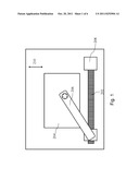
[0014] FIG. 4 is a schematic diagram for illustrating sketch structure of toggle-type with one axial positioning machine according to an embodiment of the present invention.
[0015] FIG. 5 is a diagram for illustrating a comparison between theoretical value and measured values of moving distance versus motor rotating loops of the toggle-type with one axial positioning machine.
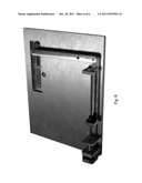
[0016] FIG. 6 is a sample photograph of the toggle-type with one axial positioning machine according to this invention.
DESCRIPTION OF THE EXEMPLARY EMBODIMENTS
[0017] The present invention provides a toggle type with one axial positioning platform. For complete understanding of the present invention, the following description will describe in detail the method steps and the components. The present invention is not limited by the specified particulars of the radiation emitting semiconductor devices that are familiar to persons skilled in the art. In addition, well-known components or method steps are not described in detail so as to avoid any additional limitation. The preferable embodiments of the present invention are described in detail. In addition to the detailed descriptions, the present invention also can be applied to other embodiments. Therefore, the scope of the present invention is not limited, and is dependent on the following claims.
[0018] This invention is designed by using tri-joints with one axial principle, as shown in FIG. 2. In FIG. 2, an upper portion and a lower portion are demonstrated for better understanding. In FIG. 2, the tri-joints indicate AB, BC and DE. With a line from A to E, two proportional triangles with different directions are formed. An intersect C, formed by the line AE and line BD and a fixed point, separates the two proportional triangles. The aforesaid principle explains that ratio of input and output is determined by the two proportional triangles. Hence, to know on triangle can verify the relationship of input and output.
[0019] This invention, by using Euler's law, calculates movement of a rigid body with a fixed point; that's a rotation around an axis. In order to express this invention more clearly, please refer to FIG. 3. The trigonometric function expression can be:
R2-R3-R4-R1=0 (1)
aejθ2-bejθ3-cejθ4-de.sup- .jθ1=0 (2)
with Euler's laws:
a(cos θ2+j sin θ2)-b(cos θ3+j sin θ3)-c(cos θ4+j sin θ4)-d(cos θ1+j sin θ1)=0 (3)
x component:
a cos θ2-b cos θ3-c cos θ4-d cos θ1=0 (4)
so,
a sin θ2-b cos θ2-c sin θ4-d=0 (5)
y component:
a sin θ2-b sin θ3-c sin θ4=0 (6),
wherein d is an independent variable, a, b, c, and θ4 are known, and θ2 and θ3 can be solved. Because R2 and R3 are equal, Δθ of θ2 and θ3 are equal.
a cos ( 90 + Δ θ ) - b cos ( 180 + Δθ ) = d - a sin Δθ + b cos Δθ = d a = b ( cos Δ θ - sin Δθ ) 2 = ( d a ) 2 cos 2 Δ θ - 2 cos Δ θ sin Δ θ + sin 2 Δ θ = ( d a ) 2 - 2 cos Δ θ sin Δ θ = ( d a ) 2 - 1 - sin ( 2 Δ θ ) = ( d a ) 2 - 1 Δ θ = 1 2 sin - 1 [ ( d a ) 2 - 1 ] ( 7 ) ##EQU00001##
[0020] With the above deduction, the upper and lower triangles are proportional, and input of d can give output value.
[0021] Back to FIG. 2, position of the fixed point C in line BD can determine sizes of the two proportional triangles, and proportional ratio of the upper and lower triangles are length DC to length BC. Therefore, distance DE can be obtained by using distance of line AB times ratio of length DC to length BC. In other words, output can be obtained by a precise input to increase precision of a platform.
[0022] One embodiment is disclosed according to above theory. Please refer to FIG. 4, a toggle-type positioning platform includes a first platform 102, a motor 104 disposed on the first platform 102, a ballscrew 110 disposed on the first platform 102 and coupled to the motor 104 such that the motor 104 can drive the ballscrew rotating, a second platform disposed on the first platform 102 and moved back and forth along a pre-determined direction 126, wherein the pre-determined direction 126 is anti-parallel to direction of the movement of the ballscrew, and a linear bearing covering the ballscrew 110 and moving with rotation of the ballscrew 110. The toggle-type positioning platform also includes a first link 114 fastened to upper portion of the linear bearing 108 and parallel to the ballscrew 110 and moved with the linear bearing 108, a second link 116, and a third link 118. the second link 116, between the first link 116 and the third link 118, is perpendicular to both first link 114 and third link 118. The third link 118 is between the second link 116 and the second platform 120, wherein rotation of the ballscrew 110 can drive the first link 114, the second link 116, and the third link 118 moving to move the second platform along the pre-determined direction 126. In order to rotate the ballscrew 110 stable, an L-support 112 is provided for supporting the ballscrew 110.
[0023] Next, the second platform 120 can move along the pre-determined direction 126 by using two rails 122. Length of the rails 122 can be about length of the pre-determined direction 126. Direction of the rails 122 can be parallel to the ballscrew 110. The rails 122 can be between the first platform 102 and the second platform 120, and can disposed on two opposite sides of the second platform 120. The first platform can have a trench (not shown in the FIG. 4) and the second platform 120 can move along the trench, wherein the trench can be V shape, U shape, or other shapes.
[0024] Then, the opposite ends of the first link 114 connect to the linear bearing 108 and the second link 116 respectively. The first link 114 and the second link 116 form a right angle. The opposite ends of the second link 116 connect to the first link 114 and the third link 118 respectively. The first link 114 is parallel to the third link 118, and the second link 116 is perpendicular to both the first link 114 and the third link 118. Further, a fixed axis 128 is disposed on the second link 116. The fixed axis 128 can make the opposite two ends of the second link 116 free rotation without movement and therefore can change angles to the first link 114 and the third link 118. The two opposite ends of the third link 118 connect to the second link 116 and the second platform 120. The connections among three links are buckled by bolts and C-hooks, and hence the angles between any two links and be varied. While the ballscrew 110 is rotated by the motor 104, the liner bearing 108 covering on the ballscrew 110 can move back or forth with rotation of the ballscrew 110. because the first link 114 is fastened to the lower portion of the liner bearing 108, and while the linear bearing 108 moves with the ballscrew 110, angles between each of the three links can be varied. The second platform 120 is then moved along the pre-determined direction 126 by the movement of the three links.
[0025] Then, a LASER meter is used to measure movement of the second platform 120. Placing a beam splitter in front of the LASER meter and a reflecting mirror on the second platform and then aligned for reflecting LASER beam. A measuring method is as follows. The beam splitter is used for splitting the LASER beam into a reference beam and a beam to be measured when it enters. The beam to be measured is then reflected back on the same path by the reflecting mirror and meets the reference beam. After analyzed by a computer, the displacement of the second platform can be known.
[0026] Table 1 is numerical analysis data of the toggle-type with one axial positioning platform according to one embodiment of the present invention, wherein the data is calculated by the measuring method described in the above paragraph.
TABLE-US-00001 TABLE 1 Loops Detect value Distance 1 0.033 0.0073 2 0.0403 0.0016 3 0.0419 0.0018 4 0.0437 0.0112 5 0.0549 0.0907 6 0.1456 0.0962 7 0.2418 0.0953 8 0.3371 0.0879 9 0.425 0.1024 10 0.5274 0.101 11 0.6284 0.0963 12 0.7247 0.0978 13 0.8225 0.1005 14 0.923 0.0978 15 1.0208 0.0975 16 1.1183 0.1 17 1.2183 0.0931 18 1.3114 0.0949 19 1.4063 0.094 20 1.5003 0.0972 21 1.5975 0.0953 22 1.6928 0.1057 23 1.7985 0.1001 24 1.8986 0.0991 25 1.9977 0.0996 26 2.0973 0.098 27 2.1953 0.0933 28 2.2886 0.1082 29 2.3968 0.1007 30 2.4975 0.0964 31 2.5939 0.1001 32 2.694 0.1018 33 2.7958 0.0992 34 2.895 0.0974 35 2.9924 0.1026 36 3.095 0.0995 37 3.1945 0.101 38 3.2955 0.1 39 3.3955 0.1003 40 3.4958 0.0977 41 3.5935 0.0935 42 3.687 0.1028 43 3.7898 0.0997 44 3.8895 0.1003 45 3.9898 0.1042 46 4.094 0.0997 47 4.1937 0.099 48 4.2927 0.0937 49 4.3864 0.1053 50 4.4917 0.0992 51 4.5909 0.0972 52 4.6881 0.1028 53 4.7909 0.1024 54 4.8933 0.0981 55 4.9914 0.1024 56 5.0938 0.092 57 5.1858 0.0973 58 5.2831 0.1101 59 5.3932 0.0955 60 5.4887 0.1025 61 5.5912 0.1006 62 5.6918 0.1045 63 5.7963 0.1003 64 5.8966 0.0996 65 5.9962 0.1006 66 6.0968 0.0984 67 6.1952 0.1019 68 6.2971 0.0998 69 6.3969 0.0998
[0027] From the table 1, a relationship between measured values of moving distance versus motor rotating loops of the toggle-type with one axial positioning machine is shown in FIG. 5. In this embodiment, number of motor's rotation loops is only to 69, but all data in the Table 1 can derive moved distance of the second platform in this invention. It is obvious that differences, between theoretical value to measured value from the first loop to the fourth loop in FIG. 5 and refer to the Table 1, have a great value. It may be incurred by tolerances of the motor or ballscrew. When the motor rotates about more than five loops, each measured moved distance is about 0.1 mm for each loop. The theoretical value of each moved distance is 0.1 mm for each loop, and averaged measured value is about 0.09972, with an error 0.00028 mm Hence, this invention can reach movement accuracy to five digits under rotation. By using this movement average value times total loops and multiplied by position of the fixed point C on the second link, moved distance of the second platform can be calculated. All experience data depend on material selected, but will not be discussed in this invention. A sample is shown in FIG. 6 for reference.
[0028] This invention discloses a toggle-type with one axial positioning machine with enhanced precision. Further, moving speed in this invention can be faster than single-link toggle type mechanism. Moreover, high precision and high resolution can be provided without using extreme delicate, complex driving server.
[0029] Although the present invention has been described in accordance with the embodiments shown, one of ordinary skill in the art will readily recognize that there could be variations to the embodiments and those variations would be within the spirit and scope of the present invention. Accordingly, many modifications may be made by one of ordinary skill in the art without departing from the spirit and scope of the appended claims.
User Contributions:
Comment about this patent or add new information about this topic:
Images included with this patent application:
 |  |
| Similar patent applications: | |
| Date | Title |
|---|---|
| 2008-10-02 | Transmission range shift control with neutral position lock |
| 2009-05-14 | Actuator with means for determining the position of an activation element |
| 2010-05-20 | Shift lever assembly with axially offset noise and vibration damper |
| 2012-01-12 | Rolling mill drive with oil recirculation system having air pressure feature |
| 2010-05-27 | Handle control provided with an angular position sensor |
| New patent applications in this class: | |
| Date | Title |
|---|---|
| 2022-05-05 | Linear actuator |
| 2022-05-05 | Spindle drive for the motor adjustment of an adjustment element of a motor vehicle |
| 2019-05-16 | Linear series elastic actuator |
| 2016-09-01 | Adapting manual laparoscopic surgical instruments for robotic telesurgery applications |
| 2016-07-14 | Steering apparatus of outboard motor and outboard motor boat |
| New patent applications from these inventors: | |
| Date | Title |
|---|---|
| 2012-01-12 | Three-link toggle type positioning platform |
| 2010-03-11 | System and method for the on-machine 2-d contour measurement |
| 2010-03-11 | system and method for on-machine 3-d depth measurement |
| 2008-11-27 | Method and apparatus for measuring weight of cnc workpieces |
| 2008-09-25 | Measuring method and system for cnc machine |
| Top Inventors for class "Machine element or mechanism" | |
| Rank | Inventor's name |
|---|---|
| 1 | Yoshimitsu Miki |
| 2 | Bo Long |
| 3 | Matthias Reisch |
| 4 | Wolfgang Rieger |
| 5 | Craig S. Ross |