Patent application title: AXIAL PISTON MACHINE
Inventors:
Manfred Kühne (Erkelenz, DE)
Manfred Kühne (Erkelenz, DE)
IPC8 Class: AF04B120FI
USPC Class:
418161
Class name: Rotary expansible chamber devices moving cylinder rotating
Publication date: 2011-10-06
Patent application number: 20110243780
Abstract:
The invention relates to an axial piston machine (1), in particular an
axial piston pump or axial piston motor, comprising a displacement piston
(24, 26) that delimits a displacement chamber (22) and that is
displacably mounted in a cylinder bore (20). Said invention is
characterised in that two displacement pistons (24, 26) that delimit the
displacement chamber (22) and that are associated with each other can be
displaced in a common cylinder bore (20) in opposite directions in
relation to each other.Claims:
1. An axial piston machine (1), in particular an axial piston pump or an
axial piston motor, with a displacement piston (24, 26) which delimits a
displacement chamber (22) and which is mounted so as to be moveable in
the cylinder bore (20), characterized in that two displacement pistons
(24, 26), which delimit the displacement chamber (22) and which are
assigned to one another, can be moved in opposite directions to one
another in a common cylinder bore (20).
2. The axial piston machine (1) according to claim 1, characterized in that the two displacement pistons (24, 26) assigned to one another are mounted opposite one another in the common cylinder bore (20).
3. The axial piston machine (1) according to claim 1, characterized in that there is an inlet opening (42) and/or an outlet opening (44) of the cylinder bore (20) between the two displacement pistons (24, 26).
4. The axial piston machine (1) according to claim 1, characterized in that an inlet opening (42) and/or an outlet opening (44) of the cylinder bore (20) runs, at least in sections, specifically on its section adjoining the cylinder bore (20), obliquely, and, specifically, transversely to the longitudinal axis of the cylinder bore (20), and preferably with the longitudinal axis of the cylinder bore (20) encloses an angle between 10 and 90.degree., specifically an angle between 45 and 75.degree..
5. The axial piston machine (1) according to claim 1, characterized in that an inlet opening (42) and/or an outlet opening (44) is located on a jacket surface of the cylinder bore (20).
6. The axial piston machine (1) according to claim 1, characterized in that between the two displacement pistons (24, 26) which are assigned to one another, there is an energy storage mechanism (163) which presses the two displacement pistons (24, 26) apart.
7. The axial piston machine (1) according to claim 1, characterized in that the axial piston machine (1) has two swash plates (40, 45), by whose plate surfaces with a drive axle (12) of the axial piston machine (1) an angle of less than 90.degree. at a time can be included.
8. The axial piston machine (1) according to claim 7, characterized in that the displacement pistons (24, 26) which are located in a common cylinder bore (20) are held in contact with one swash plate (40, 45) at a time respectively.
9. The axial piston machine (1) according to claim 1, characterized in that a low pressure port and a high pressure port of the axial piston machine (1) are located on opposite sides of the housing.
10. The axial piston machine (1) according to claim 1, characterized in that an electrical motor/generator unit is integrated in the axial piston machine (101), and that the electric motor/generator means is a brushless direct current machine, in particular, that the electrical motor/generator means can be connected to an electrical direct current line and the electrical currents in the stator windings (198) of the electrical motor/generator means can be electronically commutatable.
Description:
[0001] The invention relates to an axial piston machine, in particular an
axial piston pump or an axial piston motor, with a displacement piston
which delimits a displacement chamber and which is mounted so as to be
moveable in the cylinder bore.
[0002] Such axial piston machines can be used as pumps or as motors. In pump operation, mechanical energy is converted into hydrostatic energy, and the mechanical energy can be made available by an electric motor, for example. In motor operation, hydrostatic energy is converted into mechanical energy which can be coupled, for example, to an electromechanical generator and thus electrical energy can be generated.
[0003] The object of the invention is to make available an axial piston machine which can be used in a versatile manner. In one embodiment, continuously reliable operation is targeted with a compact design.
[0004] This object is achieved by the axial piston machine specified in claim 1. Special embodiments are specified in the dependent claims.
[0005] In one embodiment, the axial piston machine has two displacement pistons which delimit the displacement chamber, which are assigned to one another and which can be moved in opposite directions to one another in a common cylinder bore. The longitudinal axis of the cylinder bore can be coaxial to the stroke axis or an axis of symmetry of at least one, preferably both, displacement pistons. The displacement pistons can each be simultaneously moved toward one another and moved away from one another, and in this way can cause a large change of volume with comparatively small strokes. The axial piston machine thus implements a new operating principle using two opposed pistons in one common cylinder bore.
[0006] One advantage consists in extensive freedom from axial forces on the piston drum and/or the drive shaft in operation as a result of the opposed piston principle. The components of the axial piston machine are axially and/or radially centered relative to the drive axle. Only minor or no axial forces arise on the bearings of the drive shaft.
[0007] In one embodiment, the cylinder bore can be located in a cylinder drum which, on a peripheral line around a preferably central longitudinal axis, has a plurality of cylinder bores in which two displacement pistons at a time can be displaced in opposite directions to one another. In one embodiment, at a given cylinder volume, a piston stroke which is smaller compared to known axial piston machines is necessary due to the capacity of the two displacement pistons to be displaced in opposite directions, so that the piston speed is reduced accordingly. In one embodiment, bushes for the displacement pistons can be omitted.
[0008] In one embodiment, the two displacement pistons assigned to one another are mounted opposite one another in the common cylinder bore. In particular, the end faces of the displacement pistons can be facing one another and can each form an axial boundary of the displacement chamber.
[0009] In one embodiment, there is an inlet opening and/or an outlet opening of the cylinder bore between the two displacement pistons, preferably in the center between the two displacement pistons. The inlet openings and the outlet openings can be combined toward a low pressure side or a high pressure side of the axial piston machine into inlet channels and outlet channels and can be connected to a low pressure port or a high pressure port of the axial piston machine.
[0010] In one embodiment, the inlet opening and/or the outlet opening of the cylinder bore runs, at least in sections, particularly on its section adjoining the cylinder bore, obliquely and, specifically, transversely to the longitudinal axis of the cylinder bore. Preferably the inlet opening and/or the outlet opening with the longitudinal axis of the cylinder bore encloses an angle between 10 and 90°. In particular, in the case in which the inlet opening and/or the outlet opening runs radially to the inside relative to the drive axis of the axial piston machine, the angle is preferably between 45 and 75°. The extension of the openings can be straight or curved at least in sections.
[0011] In one embodiment, flow takes place radially against the displacement chamber, in any case, the flow component in the radial direction is greater than in the axial direction. In one embodiment, the cross sectional areas of the inlet and outlet channels from the medium port toward the displacement chamber, including the inlet and outlet openings to the displacement chamber, are constant or become even larger in order to prevent a pressure reduction and the resulting formation of cavities in the delivered medium. In this way, the efficiency of the axial piston machine is increased.
[0012] In one embodiment, the inlet opening and/or the outlet opening are located on a jacket surface of the cylinder bore. The axial face-side end surfaces of the displacement chamber are formed by the displacement pistons. The inlet opening and/or the outlet opening extends at least in sections, specifically on its section adjoining the cylinder bore, relative to the longitudinal axis of the cylinder bore radially to the inside or radially to the outside, specifically obliquely, i.e., with an angle between 0 and 90° to the longitudinal axis, or transversely, i.e., with an angle of 90° to the longitudinal axis. As the inlet or outlet channel there can be a collecting line which routes the inlet openings and/or outlet openings to a port of a low pressure side or to a port of a high pressure side of the axial piston machine. In one embodiment, the port for the low pressure side and/or the port for the high pressure side can be located on the axial face surfaces of the housing of the axial piston machine, specifically, centrally relative to the drive axis.
[0013] In one embodiment, there is an energy storage mechanism between the two displacement pistons which are assigned to one another, which presses the two displacement pistons apart and keeps them in contact with the respective swash plate. The energy storage mechanism can be mounted in the displacement chamber and can be formed, for example, by a helical spring. In particular, both in starting of the axial piston machine does the energy storage mechanism impart a defined position of the displacement pistons, and thus ensures reliable starting of the axial piston machine, and also in operation of the axial piston machine on the inlet side ensures contact of the displacement pistons with the swash plate assigned to them.
[0014] In one embodiment, the displacement pistons can also be held by form-fit in contact with the respective swash plate. In one embodiment, for this purpose, a preferably partially spherical end section of the displacement piston is positively held and mounted so as to be moveable in a suitably shaped receiver of the piston shoe. The piston shoe has a preferably annular contact surface for positive hold-down by means of a hold-down disk which itself is supported on a bearing element which is attached to the shaft and thus keeps the piston shoe in contact with the swash plate.
[0015] In one embodiment, the axial piston machine has a swash plate, by whose plate surface with the drive axle of the axial piston machine an angle of less than 90° can be included. The displacement pistons can be mounted in the cylinder bore to be able to move parallel to the drive axle of the axial piston machine. The angle between the swash plate and the drive axle can be adjustable, for example, in order in this way to set the geometrical displacement volume in pump operation. The optionally also adjustable angle in one embodiment is between 75 and 90°, preferably between 80 and 90°, and, specifically, between 85 and 90°. In one embodiment, the swash plate is mounted torsionally strong in the housing of the axial piston machine.
[0016] Generally, a combination of a variable speed motor with a pump with a constant geometrical displacement volume is advantageous, or a combination of a motor with constant speed and a pump with adjustable geometrical displacement volume.
[0017] In one embodiment, the displacement pistons, preferably with their axial end section, are kept in contact with one swash plate at a time and are supported on the swash plate. The contact force is made available by the system pressure and moreover, can, at least in a supportive manner, be made available by an energy storage mechanism which is mounted between the two displacement pistons. The displacement piston can be directly in contact with the swash plate or indirectly, using a so-called piston shoe in which the displacement piston is articulated. The piston shoe can be connected to the swash plate. Preferably, the displacement piston with one section is in contact with the swash plate which is opposite the section of the displacement piston which delimits the displacement chamber.
[0018] In one embodiment, a low pressure port and a high pressure port of the axial piston machine are mounted on opposite sides of the housing of the axial piston machine. The arrangement can be either on radially opposite or on axially opposite sides relative to the drive axis of the axial piston machine. The axial piston machine can have a collecting line with which the inlet openings and/or the outlet openings of several displacement chambers of the axial piston machine are connected to one another and to an assigned low pressure port or high pressure port. The collecting line can extend, at least in sections, parallel to the drive axle of the axial piston machine, or extend, at least in sections, in the peripheral direction around the drive axle of the axial piston machine.
[0019] In one embodiment, an electrical motor/generator unit with a rotor and stator is integrated in the axial piston machine. The electric motor/generator means is a brushless direct current machine. An element which has the cylinder bore for the displacement pistons can form the rotor of the electric motor/generator unit. Preferably, a cylinder drum which has cylinder bores for several displacement pistons forms the rotor of the electrical motor/generator unit.
[0020] In one embodiment, the stator has electronically commutatable stator windings. In one embodiment, the electrical current signal for the stator windings, in particular an electrical alternating signal, is generated by a trigger means from a DC voltage power supply line. The motor/generator unit can therefore have a DC terminal. By integrating an electronically commutated motor/generator unit, the axial piston machine forms a very compact electrohydraulic assembly which can be used for diverse purposes, for example even in motor vehicles, aircraft, or ships and in other domains, in which there is a DC voltage supply, for example from a battery. Use in the under oil domain is also possible due to the compact construction and electronic commutation using simple means. Moreover, the assembly according to the invention can not only be easily supplied from a battery system, but hydraulic energy can also be recovered by the hydraulic means being operable as a motor means and, accordingly, the electrical means as a generator means.
[0021] In one embodiment, the electrical motor/generator unit has a control means and sensorless triggering of the stator windings. For this purpose, the change of phase inductances is evaluated by flux changes in the iron core which are caused specifically by the rotor. For this purpose, the neutral point potential in certain operating states of the phases can be measured and the motor can be used as an inductive measurement bridge for determining the relative phase inductances.
[0022] Other advantages, features and details of the invention will become apparent from the dependent claims and the following description in which several embodiments are described in detail with reference to the drawings. In this connection, the features mentioned in the claims and in the specification are each essential for the invention individually for themselves or in any combination thereof.
[0023] FIG. 1 shows a longitudinal section through a first embodiment of an axial piston machine according to the invention,
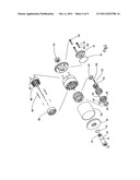
[0024] FIG. 2 shows an exploded view of the first embodiment of the axial piston machine of FIG. 1,
[0025] FIG. 3 shows a longitudinal section through a second embodiment of an axial piston machine according to the invention,
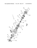
[0026] FIG. 4 shows an exploded view of the second embodiment of the axial piston machine of FIG. 3,
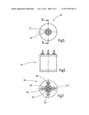
[0027] FIG. 5 shows a face-side view of the second embodiment of FIG. 3,
[0028] FIG. 6 shows a side view of the second embodiment of FIG. 3, and
[0029] FIG. 7 shows a front view of the second end face of the second embodiment of FIG. 3.
[0030] FIG. 1 shows a longitudinal section through a first embodiment of an axial piston machine 1 according to the invention, and FIG. 2 shows an exploded view of the first embodiment of the axial piston machine 1 of FIG. 1. Preferably, the drive shaft 10 is located essentially centrally in a housing along the drive axle 12 and emerges at least on one face surface from the housing of the axial piston machine 1 and has a toothed shaft journal 14 for coupling the axial piston machine 1 to a motor or a generator. Within the housing the drive shaft 10 preferably axially has essentially in the center a toothed section 16 by means of which the drive shaft 10 is connected torsionally strong to the cylinder drum 18. In the cylinder drum 18, which is arranged concentrically to the drive axle 12 and which is pivoted around it within the housing, there are several cylinder bores 20 (FIG. 2) which run parallel to the drive axle 12 and which are arranged along a circular peripheral line around the drive axis 12.
[0031] In each cylinder bore 20 there are two displacement pistons 24, 26 which delimit the displacement chamber 22, which are assigned to one another, and which can be moved opposite one another in the common cylinder bore 20. On their end faces which are assigned to one another, the displacement pistons 24, 26 are preferably essentially planar. On their opposite end section, the displacement pistons 24, 26 each form an at least partially spherical end section 28, 30, specifically a type of spherical head, with which the displacement pistons 24, 26 are articulated in one receiving element 32, 34 respectively which can also be referred to as a piston shoe. All receiving elements 32, 34 of one side of the axial piston machine 1 are located in a hole of the hold-down disk 36 at a time; the center hole of the latter slides on a partially spherical surface of the bearing element 38 which can be connected to the drive shaft 10.
[0032] With its end section which is opposite the displacement piston 24, 26, the receiving element 32 is in contact with a swash plate 40 so that when the cylinder drum 18 and the co-rotating displacement pistons 24, 26 rotate as a result of the oblique position of the swash plate 40 relative to the drive axle 12, lifting motion of the displacement pistons 24, 26 in the cylinder bore 20 takes place. The angle enclosed by the swash plate 40 and the drive axle 12 in one embodiment is between 75 and 90°, preferably between 80 and 90°, and, specifically, between 85 and 90°. At an angle of 90°, when the cylinder drum 18 rotates, there is no lifting motion of the displacement pistons 24, 26.
[0033] Approximately in the center, relative to the axial extension of the cylinder drum 18, it has inlet openings 42 and outlet openings 44 which are oriented radially to the outside proceeding from the cylinder bores 20; fluid can flow into the displacement chamber 22 and out of the displacement chamber 22 through the inlet and outlet openings. For each cylinder bore 20 there is an inlet opening 42 or an outlet opening 44 which extend radially relative to the drive axle 12, i.e., at a right angle to the drive axle 12. The inlet openings 42 and outlet openings 44 are also located in the center relative to the two displacement pistons 24, 26 and, moreover, determine a plane of separation which runs at a right angle to the drive axle 12 and which can also form a plane of symmetry relative to the arrangement of the displacement pistons 24, 26 and the receiving elements 32 and the swash plates 40 at both sides of this plane of separation.
[0034] In one embodiment, the angle included between the swash plate 40 and the drive axle 12 can be adjusted. For this purpose, the axial piston machine 1 has a setting means with a control valve 48 mounted on the jacket surface of the essentially hollow cylindrical base housing part 46. Aside from the control valve 48, the setting means is built essentially symmetrically to an axial center plane. The control valve 48 is connected by way of a control channel 52 to a control cylinder 54 which is aligned parallel to the drive axle 12. In the control cylinder 54 there is a control piston 56 which is in contact with the swash plate 40. Radially opposite relative to the drive axle 12, there is a spring force-preloaded lead piston 58 applying a moment which causes the oblique position to the swash plate 40.
[0035] When the control piston 56 is pressurized, it travels out of this control cylinder 54 and thus changes the oblique position of the swash plate 40 relative to the drive axle 12. If the control piston 56, proceeding from the initial position shown in FIG. 1 via the right-angle position of the swash plate 40 relative to the drive axle 12, is driven out of the control piston 54, the high pressure port becomes the low pressure port of the axial piston machine 1 and vice versa. The control piston 56 and the lead piston 58 are mounted in a first bearing element 62 which has a through opening for another shaft journal 64 and which can be closed on the end side with a cover 66.
[0036] On the axially opposite side there are another lead piston 68 and another control piston 72 which are mounted in a second bearing element 74 in which there is also a shaft bearing 76. The shaft bearing 76 is fixed axially relative to the drive shaft 10 by two snap rings 78, 82 which are inserted into a groove 84, 86 of the drive shaft 10 respectively. On the end side, the second bearing element 74 is sealed by a flange 88, both the second bearing element 74 and also the flange 88 having a through opening for the drive shaft 10.
[0037] The inlet openings 42 and outlet openings 44 of each cylinder bore 20 are combined into collecting lines which can be arranged, for example, on the inside of the base housing 46 and are connected to a high pressure port 92 and a low pressure port 94 which are arranged relative to the drive axle 12 on opposite sides on the jacket surface of the base housing part 46.
[0038] The displacement pistons 24, 26 each have a preferably center bore 70 which proceeds from their face sides which are assigned to one another. In the receiving element 32 there is a bore which is fluid-connected to the bore 70 in the displacement piston 24, 26 and which can be made as a stepped bore. A section of the stepped bore facing the displacement piston 24, 26 has a greater diameter than a section facing the swash plate 40; preferably, the diameter in the section which is facing the displacement piston 24, 26 matches the diameter of the hole 70 in the displacement piston 24, 26. On the face side which is facing the swash plate 40, the receiving element 32 has a preferably centered, plate-shaped depression which acts as a hydrostatic bearing.
[0039] FIG. 3 shows a longitudinal section through a second embodiment of an axial piston machine 101 according to the invention which is structurally very similar or identical in numerous details to the first embodiment of FIG. 1 and, in this case, reference numbers with values raised by 100 are also used for the components. FIG. 4 shows an exploded view of the second embodiment of FIG. 3.
[0040] FIG. 5 shows a face-side view of the second embodiment of the axial piston machine 101 of FIG. 3 with a first blind hole bore 117 which forms the inlet of the axial piston machine 101. FIG. 6 shows a side view of the second embodiment and FIG. 7 shows a front view of the second face side with a second blind hole bore 119 which forms the outlet of the axial piston machine 101.
[0041] One important difference of the second embodiment consists in that an electric motor/generator unit is integrated into the axial piston machine 101. The motor/generator unit comprises a rotor which is formed by the cylinder drum 118 and a stator which is formed by a core 196 which conducts the magnetic flux and by an associated coil winding 198. Accordingly, for the axial piston machine 101 a drive shaft does not emerge from the housing.
[0042] The displacement pistons 124, 126 which are mounted in the cylinder bore 120 and which are assigned to one another are held by an energy storage mechanism 163 mounted between them and in the displacement chamber 163, in the embodiment a helical spring, in contact with swash plates 140, 145 which are assigned to them and which are mounted stationary in the housing of the axial piston machine 101. In particular, the swash plates 140, 145 are centered by contact with the control element 111 and are fixed and protected against turning in the housing part by means of one brace 141, 143, respectively.
[0043] Centered in the housing and coaxially to the longitudinal axis 112, there is a control element 111 which is essentially cylindrical in the embodiment and which is connected fluid-tight to a cover 115 which is located axially on the face side by means of a sealing element 113, which forms a bearing for the cylinder drum 118, and which is also referred to as a control journal. In sections, the control element 111 has blind hole bores 117, 119 which proceed from the two face-side ends, the first blind hole bore 117 having a greater diameter than the second blind hole bore 119. The blind hole bores 117, 119, by way of inlet openings and outlet openings 144, connect the displacement chambers 122 to ports for the low pressure side and the high pressure side of the axial piston machine 101. The inlet openings and outlet openings 144 run obliquely to the longitudinal axis 112 and with it include preferably an angle between 45 and 75°. The blind hole bores 117, 119 are connected via through openings 121 (FIG. 4) to the jacket surface of the control element 111, the through openings 121 being able to extend more or less semicircularly over the jacket surface of the control element 111 and being able to become connected to the inlet and outlet openings 144 when the cylinder drum 118 rotates. At the same time, the control element 111 with its circularly cylindrical jacket surface forms a bearing site for the rotating cylinder drum 118.
[0044] The control element 111 on the face-side entry of the first blind hole bore 117 has an internal thread 123 which forms the low pressure port or inlet for the axial piston machine 101. On the axially opposite end, the control element 111 on the face-side entry of the second blind hole bore 119 has another internal thread 125 for the port of the high pressure side of the axial piston machine 101. Moreover, the control element 111 in the region of the second blind hole bore 119 on the end side has an external thread 127 for screwing on a sealing nut 129 by means of which the control element 111 is tightly connected to another cover 131 of the housing.
[0045] Distributed around the circular periphery, permanent magnets 135 are fixed to the jacket surface of the cylinder drum 118, which are inserted preferably into the corresponding axially running grooves 137 on the jacket surface of the cylinder drum 118, and can be fixed there by clamping and/or by a connecting means, in particular, can be cemented in. The cylinder drum 118 provided with the permanent magnets 135 forms the rotor for the motor/generator unit of the second embodiment.
[0046] The coil windings 198 and the magnetically conductive core 196 are located on a stator body 197 which is fixed by means of connecting elements 199, for example assembly pins, on the cover 115 and/or the other cover 131. Radially on the outside, a tubular housing part 150 closes off the axial piston machine 101. The tubular housing part 150 is located between the cover 115 and the other cover 131 and is tightly connected to the cover 115 and the other cover 131 by means of the sealing elements 151, in the embodiment to gaskets.
[0047] As follows from the face-side view of FIG. 7, on the outlet side of the axial piston machine 101 in addition to the electrical terminals 153 of the stator windings 198 which are connected to the other cover 131 via penetrations 155, the associated insulating elements 161 and sealing elements 157, 159, a terminal 160 of a sensor which is also located optionally in the region of the coil winding 198 is routed to the outside. The sensor can be, for example, a temperature sensor and/or can enable detection of the rotor position for electronic commutation of the coil windings 198 by means of a trigger circuit which can be supplied for its part by way of a direct current supply. The control means can also be integrated into the housing of the axial piston machine 101 so that the housing has only one direct current terminal.
[0048] In one embodiment, a leakage current can be made available by undersizing of the displacement pistons 124, 126 relative to the cylinder bore 120 and/or the cylinder drum 118 relative to the control element 111 or the control journal; this current causes a volumetric cooling flow for efficient cooling of the motor/generator unit, as a result of which, even for a very compact design, high performance of the axial piston machine 101 can be achieved. In this way the cooling fins which are otherwise conventional in electrical machines can be omitted.
User Contributions:
Comment about this patent or add new information about this topic:
Images included with this patent application:
 |  |
 |  |
 |
| Similar patent applications: | |
| Date | Title |
|---|---|
| 2008-10-16 | Self-aligning rotary pistone machine |
| 2009-01-22 | Asynchronous non-constant-pitch spiral scroll-type fluid displacement machine |
| 2009-03-26 | Peripherally pivoted oscillating vane machine |
| 2010-06-17 | System for sealing the piston of rotary piston machines |
| 2008-09-11 | Rotary piston machine |
| New patent applications in this class: | |
| Date | Title |
|---|---|
| 2015-02-19 | Hydraulic machine, in particular hydraulic pressure exchanger |
| 2012-09-20 | Hydraulic motor or pump with tangential pistons with annular or sectional shape on ordinary or planetary gear for high torque, and power performance and hydraulic and mechanical efficiency |
| 2012-07-12 | Rotary cylinder device |
| 2010-07-15 | Accurate powder metal component, assembly and method |
| 2009-01-15 | Gear pump |
| Top Inventors for class "Rotary expansible chamber devices" | |
| Rank | Inventor's name |
|---|---|
| 1 | Byeongchul Lee |
| 2 | Masanori Masuda |
| 3 | Robert C. Stover |
| 4 | Masao Akei |
| 5 | Rene Schepp |