Patent application title: INDOOR-OUTDOOR EXERCISE SLED APPARATUS
Inventors:
Douglas D. Larish (Tempe, AZ, US)
IPC8 Class: AA63B2106FI
USPC Class:
482 93
Class name: Exercise devices user manipulated force resisting apparatus, component thereof, or accessory therefor utilizing weight resistance
Publication date: 2011-09-15
Patent application number: 20110224050
Abstract:
An indoor-outdoor manually-propelled variable-resistance exercise sled
for one or multiple users. The exercise sled features a rigid and durable
weight-bearing platform. To protect indoor flooring surfaces, a
removable, flexible, non-grip protective pad may be attached to the
bottom of the exercise sled. When the protective pad is removed, the
exercise sled can also be used on most outdoor ground surfaces. The
exercise sled includes dual attachment plates at opposite ends to provide
multiple force application points to permit a variety of optional
implements to be connected to the exercise sled. A removable handle
assembly provides an additional force application surface. In
combination, the various attachment points afford a multitude of pulling
and pushing, lower-extremity and upper-extremity, functional exercises
for one or simultaneously by multiple users.Claims:
1. A manually propelled variable resistance exercise sled for use on
indoor floor and outdoor ground surfaces for performing lower extremity
pushing and pulling exercises by one or multiple individuals comprising:
a) a weight bearing platform having a superior surface and an inferior
surface, said weight bearing platform having a front and rear; b) a front
attachment plate coupled on said weight bearing platform front; c) a rear
attachment plate coupled on said weight bearing platform rear; d) a
weight attachment structure coupled to said weight bearing platform
superior surface; e) a removable anti-grip protective pad affixed to said
weight bearing platform, whereby said pad at least partially covers said
platform inferior surface; and f) a removable handle assembly affixed to
said platform at least one of said front and rear attachment plates.
2. The exercise sled of claim 1 wherein said weight bearing platform is made from a material that has similar friction properties to a standard manufactured high-density polyethylene materials.
3. The exercise sled of claim 1 wherein said weight bearing platform, said front and rear attachment plates and said weight attachment structure are formed in a single unitary body.
4. The exercise sled of claim 1 wherein: said weight bearing platform has a generally rectangular inferior surface; and wherein said weight bearing platform inferior surface comprises rounded corner edges.
5. The exercise sled of claim 1 wherein said front and rear attachment plates affix to said weight bearing platform superior surface whereby said front attachment plate and said rear attachment plates align generally parallel to one another.
6. The exercise sled of claim 1 wherein each of said front and rear attachment plates comprise at least two attachment means for affixing a removable implement.
7. The exercise sled of claim 1 wherein said weight attachment structure comprises a flange base coupled to the superior surface of said weight bearing platform.
8. The exercise sled of claim 7 further comprising a rod oriented perpendicular to said weight bearing platform superior surface, said rod being affixed to said weight attachment structure; whereby said rod allows for the stacking of a suitable weight device.
9. The exercise sled of claim 1 wherein said anti-grip protective pad comprises suitable properties to lower the friction and shield the weight bearing platform inferior surface and allow the exercise sled to slide across a ground surface.
10. The exercise sled of claim 9 whereby said anti-grip protective pad comprises attachment means for coupling with at least one of said front and rear attachment plates.
11. The exercise sled of claim 1 whereby said removable handle assembly comprises a removable U-shaped bracket.
12. The exercise sled of claim 11 whereby said removable handle assembly is coupled to at least one of said front and rear attachment plates.
13. The exercise sled of claim 11 further comprising an adjustable force application structure capable of removably coupling with said handle assembly.
14. An exercise sled for use on ground surfaces for performing exercises by one or multiple individuals comprising: a) a weight bearing platform having a superior surface and an inferior surface; b) a front attachment plate coupled on said weight bearing platform superior surface; c) a weight attachment structure coupled to said weight bearing platform superior surface; d) an anti-grip protective pad affixed to said weight bearing platform, whereby said pad at least partially covers said platform inferior surface; and e) a handle assembly coupled to said platform.
Description:
FIELD OF INVENTION
[0001] The present invention relates to a manually-propelled variable-resistance exercise apparatus that can be used on both indoor and outdoor surfaces, provides the versatility to allow a multitude of upper body and lower body functional exercises, and permits multiple users to work mutually together or in opposition. In this regard, the present invention, relates to the general field of fitness and exercise.
BACKGROUND OF INVENTION
[0002] Within the exercise and fitness industry, functional training has become a popular mode of exercise. Unlike most traditional exercise programs that rely on machines and weight equipment found in a typical health and fitness club, functional training emphasizes exercises that simulate movements that are common in one's everyday life. The focus is on ground-based, multi-joint, multi-muscle, and multi-planar movements that require core involvement, balance, coordination, and timing instead of simple single-joint, single-muscle exercises in which you lay or sit fully supported on a bench.
[0003] High intensity interval training has also become a popular mode of exercise. High intensity means that the exerciser works at a very high percentage of their maximal heart rate (e.g., 80% or above). Interval training means that the workout involves alternating periods of high intensity (exercise) and low intensity (recovery) intervals. The exact ratio of the work-to-recovery interval is determined by ones specific workout goal (e.g., muscle power, speed endurance, muscular endurance). Recent research shows that there are several advantages of high intensity interval training over more traditional exercise regimens: It can lead to the simultaneous improvement of multiple fitness variables, such as muscle strength, muscle hypertrophy, muscle power, muscle endurance, speed endurance, mobility, cardio-respiratory fitness, and post-workout basal metabolic rate. No other exercise regimen can make or support this claim. You can achieve the aforementioned improvements in a significantly shorter period of time than it takes with alternative exercise regimens. Although these workouts are completed in a shorter period of time, they produce greater calorie expenditure (both glycogen and fat) relative to alternative exercise regimens. High intensity interval training also boosts ones post-workout basal metabolic rate, which promotes the loss of body fat even after the workout has been completed.
[0004] To merge functional training with high intensity interval training, the exercise and fitness industry has moved away from traditional weight training equipment (e.g., selectorized machines) in favor of exercises that rely simply on body weight, or the use of dumbbells, kettlebells, clubbells, resistance bands and tubing, and manually propelled weighted sleds.
[0005] In the current art, the most common weighted sleds are designed for athletic training particularly for use with football and track athletes. Examples of such devices are U.S. Pat. No. 5,385,523, US D478,954, D466,963, D469,142, D562,417, and US 2008/0312009 A1, as well as those commercially available. All of these sleds have one common feature: Their major weight bearing surfaces are manufactured from metal or aluminum tubing, sheeting, and/or plating. Very recently a newer generation of weight sleds made from non-metallic materials has shown up in the commercial market. Regardless of whether the current art of manually propelled weight sleds are made from metallic or non-metallic parts and structures, they all have one or more limitations that severely restrict their utility in an exercise and fitness setting.
[0006] Metal based training sleds are designed for outdoor use on grass or dirt, and perhaps sand and some types of artificial surfaces (if the amount of added weight is not substantial). They cannot, however, be used on surfaces typically found in an indoor exercise setting, such as wooden floors of gymnasiums, rubberized floors of fitness centers and weight rooms, nor linoleum, tile, or carpeted surfaces. The hardness of the metal, combined with frictional forces created by their metallic bases, can cause significant damage (e.g., gouges, scrapes, tears, and discoloration) to all of these surfaces. Such damage is of particular concern with those training sleds that use narrow runners (e.g., U.S. Pat. No. 5,385,523; US D562417) because their small footprint concentrates contact and frictional forces in a small surface area; the heavier the weight on the training sled the greater the potential for wear and tear damage to the sliding surface.
[0007] In an exercise or fitness setting, a manually propelled weight sled that can be used both indoors and outdoors would be more practical. To achieve such versatility, the main weight bearing components of the platform that contact the floor or ground must be made from materials that 1) do not mar any indoor floor surface, 2) are not adversely affected by outdoor environmental conditions, 3) have frictional properties low enough to permit movement across any indoor flooring surface as well as most outdoor ground surfaces, and 4) distribute contact and frictional forces, particularly with heavy weight, over a large enough surface area so as to eliminate their potential damaging effects of floor or ground. These four design considerations are uniquely met in the present invention.
[0008] Although the new generation of non-metallic sleds may be used indoors, they suffer from yet another restriction that is also associated with metal based sleds: both types have a limited number of exercise options. They are designed primarily for resisted running exercises or pushing a blocking/tackling target. Such a limitation is inherent in the design of current art because most have only one fixed point of force application on one end of the training sled. Some training sleds can only be pulled horizontally from one set vertical height (e.g., US D562417). Still other training sleds can only be pushed horizontally from one set vertical height. Thus, some newer current art has combined pushing and pulling from different levels of force application. However, none have multiple points of force application at varying heights on both ends of the training sled. Given the design constraints outlined above, it is reasonable to state that all of the current art restricts the type and number of lower body and upper body functional training exercises that they allow.
[0009] Three additional design limitations are noteworthy. First, the non-metal training sleds have weight limits (100 lbs or less) that may preclude the user from experiencing an overload training effect; this is especially true for highly fit individuals. Improvements in the physiological variables associated with exercise can only be realized if this overload effect is experienced and constantly modified as an individual's fitness level improves. Thus, any useful training sled must have a sufficiently variable range of resistance levels to create the overload effect in users of any fitness and exercise level. Second, except for the US 2008/0312009 and perhaps one commercial system, all other non-football blocking/tackling sleds are limited to one user; however, neither of these can be used on all indoor floor surfaces. An exercise sled that allows multiple users to concurrently work in concert or in opposition would add a level of utility not available in the current art. For example, two or more users might push the exercise sled in a common direction. Alternatively, two or more users might pull against the exercise sled (using straps or ropes) from opposite directions creating a tug-o-war scenario. This latter option is unique to the present invention. Third, when all of the current art is collectively considered, there is some variety in the exercises that are available to the user. However, you need multiple sleds to take advantage of this variety. It would be more advantageous and cheaper for the user if only one exercise sled were needed. The present invention affords the desired versatility discussed above but eliminates the need for more than one sled.
[0010] In many exercise and workout settings, it is desirable to have one manually propelled exercise sled that allows a wide range of lower extremity and upper extremity functional exercises. To achieve such versatility, the exercise sled must have 1) multiple directions of force application, 2) multiple vertical heights of force application, and 3) multiple attachment devices (e.g., webbing straps, ropes, handles, resistance bands or tubing). Moreover, the manually propelled exercise sled must have the weight range and capacity to create an exercise overload affect for both novice and highly trained individuals. A further desirable feature is the ability to have multiple users who can exercise either in concert with or in opposition to each other.
[0011] Accordingly, a need exists for a manually propelled exercise sled apparatus that can be used on any indoor flooring surface without causing damage to said surfaces.
[0012] Accordingly, a need exists for a manually propelled exercise sled apparatus that can be used on most outdoor ground surfaces without causing damage to either the weight bearing element of the sled and to said outdoor surfaces.
[0013] Accordingly, a need exists for a manually propelled exercise sled apparatus that can be used in both an indoor and outdoor exercise setting without the requirement of separate apparatus'.
[0014] Another need exists for a manually propelled exercise sled apparatus that has multiple points of force application providing versatility to include a wide array of multi-directional pushing and pulling lower extremity functional training exercises without the need of separate apparatus'.
[0015] Another need exists for a manually propelled exercise sled apparatus that has multiple points of force application providing versatility to include a wide array of multi-directional pushing and pulling upper extremity functional training exercises without the need of separate apparatus'.
[0016] Another need exists for a manually propelled exercise sled apparatus that is resistant to the effects of adverse environmental conditions such as extreme heat, humidity, and moisture.
SUMMARY OF INVENTION
[0017] The present invention relates to an indoor-outdoor exercise sled designed for use in an exercise and fitness environment. The features that make the present invention unique and novel are: 1) The use high density polyethylene materials to create an exercise sled that is rigid, durable, and of suitable size and shape that it can used both indoors and outdoors without causing wear and tear damage to floor or ground surfaces, 2) The use of a removable and replaceable anti-grip protective pad when the high density polyethylene surface of the exercise sled might damage an indoor floor surface, 3) The positioning of duplicate and multiple attachment points at both ends of the exercise sled providing the user with a larger array of upper and lower extremity pulling and pushing exercises than the current art allows via use of one sled, 4) The ability of multiple users to simultaneously exercise either in concert with or opposition to each other, and 5) The inclusion of a removable and adjustable handle assembly that affords the user additional force application points adjusted to their physical stature and physical condition. The indoor-outdoor exercise sled includes the following interrelated objects, aspects, and features:
[0018] The manually propelled variable resistance exercise sled apparatus, in accordance with the teachings of the present invention, includes a weight bearing platform having a front attachment plate, a rear attachment plate, and a weight attachment structure affixed to the superior surface of the weight bearing platform. A flexible anti-grip protective pad can be selectively attached or removed from the inferior surface of the weight bearing platform. A removable and adjustable handle assembly may be affixed to the rear attachment plate.
[0019] The weight bearing platform is made from high density polyethylene sheeting or a similarly manufactured material with comparable structural properties, which, because of its structural properties, provides a low coefficient of friction when placed in sliding contact with other surfaces, such as against a floor/ground surface, is extremely durable, and is impervious to the deleterious effects of harmful environmental conditions. As such, this allows the exercise sled to be used on any indoor floor and most outdoor ground surfaces.
[0020] The front attachment plate includes attachment points (e.g., eye bolts) affixed to the anterior lateral surface of the front plate. When various attachment mechanisms, such as web straps or a rope are affixed to these attachment points, the exercise sled can be pushed or pulled in two dimensional space via force production from both upper and lower extremity musculature.
[0021] The rear attachment plate includes attachment points (e.g., eye bolts) affixed to the posterior lateral surface of the rear plate. When various attachment mechanisms, such as web straps or a rope are affixed to these attachment points, the exercise sled can be pushed or pulled in two dimensional space via force production from both upper and lower extremity musculature.
[0022] The weight attachment structure includes a flange that acts as a base for a removable and adjustable extension rod. In combination, the flange base and extension rod provide a means for securing a variety of different types of weights on the weight bearing platform.
[0023] The removable flexible anti-grip protective pad includes an inferior surface that provides low friction properties when used in combination with most floor or ground surfaces upon which it moves; thus permitting it to slide across these surfaces in two dimensional space. The pad also acts as a protective barrier to prevent damage to indoor surfaces. When the protective pad's low friction properties are not necessary for proper use and movement of the sled, the pad can be removed so that the exercise sled can still be moved in two dimensional space.
[0024] The removable handle assembly includes a U-shaped bracket and a removable force application structure. The U-shaped bracket attaches to either the front or rear attachment plate and the force application structure inserts into the bracket via two upwardly angled sleeves that are themselves affixed to the bracket. When a pushing or pulling force is applied to the handle assembly, the exercise sled is moved in two dimensional space.
[0025] These and other objects, aspects, and features of the present invention will be better understood from the following detailed description of the preferred and alternative embodiments when read in conjunction with the appended drawings and figures.
BRIEF DESCRIPTION OF THE DRAWINGS
[0026] The above and further advantages of the invention may be better understood by referring to the following description in conjunction with the accompanying drawings in which:
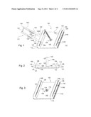
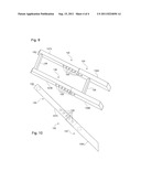
[0027] FIG. 1 illustrates a perspective elevation of one embodiment of an indoor-outdoor manually propelled exercise sled apparatus and a removable handle assembly attached thereto in accordance with the principles of the present disclosure;
[0028] FIG. 2 illustrates a right side view of one embodiment of an indoor-outdoor manually propelled variable resistance multidirectional push pull exercise apparatus (left side view is a mirror image) in accordance with the principles of the present disclosure;
[0029] FIG. 3 illustrates a perspective view of one embodiment of an indoor-outdoor manually propelled exercise sled apparatus in accordance with the principles of the present disclosure;
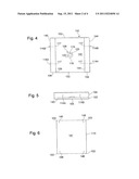
[0030] FIG. 4 illustrates a top view of one embodiment of an indoor-outdoor manually propelled variable resistance exercise sled apparatus in accordance with the principles of the present disclosure;
[0031] FIG. 5 illustrates a front view of one embodiment of an indoor-outdoor manually propelled variable resistance exercise sled apparatus (rear view is a mirror image) in accordance with the principles of the present disclosure;
[0032] FIG. 6 illustrates a bottom view of one embodiment of an anti-grip protective pad in accordance with the principles of the present disclosure;
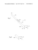
[0033] FIG. 7 illustrates a side view of one embodiment of a removable bracket and sleeve structure of the removable handle assembly in accordance with the principles of the present disclosure;
[0034] FIG. 8 illustrates a perspective elevation of one embodiment of a molded removable force application structure in accordance with the principles of the present disclosure;
[0035] FIG. 9 illustrates a perspective elevation of one embodiment of a telescoping removable force application structure in accordance with the principles of the present disclosure;
[0036] FIG. 10 illustrates a side view of one embodiment of a telescoping removable force application structure in accordance with the principles of the present disclosure;
DETAILED DESCRIPTION
[0037] The indoor-outdoor manually propelled variable resistance exercise sled apparatus, including an illustrative embodiment and various alternative embodiments are described hereinafter in greater detail with reference to FIGS. 1-10.
[0038] In the preferred embodiment as illustrated in FIG. 1, an indoor-outdoor manually propelled variable resistance exercise sled 100 comprises a rigid rectangular weight bearing platform 102, a rigid front attachment plate 104, a rigid rear attachment plate 106, a weight attachment structure 108, a flexible anti-grip protective pad 110, and a mechanism for mounting a removable handle assembly 112.
[0039] Weight bearing platform 102 (see FIGS. 1-5) is preferably formed from high-density polyethylene sheeting, or any other similarly manufactured material with comparable structural properties. Because of its physical, mechanical, and thermal properties, any structures made from high-density polyethylene sheeting will generally not splinter, crack, delaminate, or rot; nor will they easily degrade with prolonged exposure to environmental conditions such as direct sun and water making them virtually maintenance free. In addition, high-density polyethylene sheeting has low friction properties making it an ideal sliding material. Its low friction properties also allow weight bearing platform 102 to physically contact the floor or ground surface as it is being moved. As such, it is possible to make said platform of a sufficient size so as to dissipate downward and frictional forces over a large enough area so that wear and tear damage to floor and ground surfaces is not a concern. Thus, the weight bearing platform 102 represents an extremely durable and rigid structure that is nearly impervious to damage yet can slide across virtually any floor or ground surface. Despite the advantageous properties of high density polyethylene sheeting, the pressure and friction caused by sliding a weighted structure may still damage some indoor floor surfaces, such as wood, tile, and linoleum. In such cases, weight bearing platform 102 inferior surface is provided with a removable anti-grip protective pad 110. The inferior surface of the anti-grip protective pad 110 has friction properties low enough to permit movement of the weight bearing platform 102 and is made from soft, flexible materials that prevent said platform from marring the floor surface in any way. In the preferred embodiment, anti-grip protective pad 110 is formed from a standard indoor-outdoor carpet as is known in the art. Furthermore, the four edges of the inferior surface of weight bearing platform 102 are rounded to prevent said platform from digging into the floor or ground surface.
[0040] The front attachment plate 104 (see FIGS. 1-5) is made from solid core polyethylene tubing or any other similarly manufactured material with comparable structural properties and is affixed to the superior surface of the weight bearing platform 102 parallel to and in line with the width of said platform's anterior edge. The front attachment plate 104 is provided with two attachment points shown as rounded eyebolts 114A-B (see FIG. 2) affixed on the anterior surface at the lateral edges centered between the superior and inferior surfaces of said plate. In the preferred embodiment, two eye bolts are positioned horizontally through the width of the front attachment plate and held in place with suitable nuts and washers on the posterior side of said plate. For safety purposes, the exposed threaded ends of the eye bolts 114A-B are covered by an appropriately sized cap nut or acorn nut. Using a variety of suitable removable implements, such as webbing straps, ropes, cords, and chains (not shown), attached via a suitable removable connector, such as carabineer, quick link, spring clip, or other suitable fastening device (not shown) to the eyebolts 114A-B, the user can perform a multitude of pulling exercises using upper extremity and lower extremity musculature. The weight bearing platform 102 can be further moved in two-dimensional space by applying a pushing force from a mountain climber position against the anterior surface of the front attachment plate 104. Removable resistance bands and resistance tubing (not shown) may also be affixed to said eyebolts so that the user can perform a wide array of upper extremity pushing and pulling exercises. In an alternative embodiment, eye bolts 114A-B may be positioned on the superior surface of the said front plate. In alternative embodiments, said front plate may be implemented with hollow core polyethylene tubing, steel tubing, a fibrous material such as wood, or any other suitably rigid material.
[0041] The rear attachment plate 106 (see FIGS. 1-5) is made from solid core polyethylene tubing or any other similarly manufactured material with comparable structural properties and lies on the superior surface of the weight bearing platform 102 parallel to and in line with the width of said platform's posterior edge. The rear attachment plate 106 is implemented with two rounded eyebolts 116A-B affixed on the posterior surface at the lateral edges centered between the superior and inferior surfaces of said plate. In the preferred embodiment, two attachment points shown as eye bolts are positioned horizontally through the width of the front attachment plate and held in place with suitable nuts and washers on the anterior side of the rear attachment plate 106. For safety purposes, the exposed threaded ends of the eye bolts 116A-B are covered by an appropriately sized cap nut or acorn nut. Using a variety of suitable removable implements, such as webbing straps, ropes, cords, and chains (not shown), attached via a suitable removable connector, such as carabineer, quick link, spring clip, or other suitable fastening device (not shown) to the eyebolts 116A-B, the user can perform a multitude of pulling exercises using upper extremity and lower extremity musculature. The weight bearing platform 102 can be further moved in two-dimensional space by applying a pushing force from a mountain climber position against the posterior surface of the rear attachment plate 106. Removable resistance bands and resistance tubing (not shown) may also be affixed to said eyelets so that the user can perform a wide array of upper extremity pushing and pulling exercises. In an alternative embodiment, eye bolts 116A-B may be positioned on the superior surface of the said rear plate. In alternative embodiments, said rear plate may be implemented with hollow core polyethylene tubing, steel tubing, a fibrous material such as wood, or any other suitably rigid material.
[0042] Because the weight bearing platform 102 is outfitted with two attachment plates 104 and 106, and each has their own two respective attachment points 114A-b and 116A-b, it is possible for two individuals to simultaneously use the exercise sled. They can work together in a coordinated fashion to pull the weight bearing platform 102 in the same direction. For example, by separately connecting two webbing straps to the attachment points 114A-B, two users can simultaneously pull the exercise sled 100 horizontally forward. Moreover, the unique configuration of the two attachment plates 104 and 106, makes it possible for two users to work against each other in an opposing fashion; that is, they can push or pull against opposite ends of the front and rear attachment plates to resist the others desired direction of movement in "tug-o-war" fashion. For example, separate ropes can be attached to the attachment points on the front attachment plate 104 and rear attachment plate 106. One or more users can pull on each rope in opposite directions thereby creating the tug-o-war exercise. Moreover, via the use of removable connectors to the attachment points 114A-B and 116A-B, it is a quick and easy matter to attach and detach a multitude of pushing or pulling implements.
[0043] The superior surface of the weight bearing platform 102 intermediate to the front attachment plate 104 and the rear attachment plate 106 supports removable weights to accommodate varying levels of resistance. A weight attachment structure 108 (see FIG. 1) is centrally affixed and parallel to the superior surface of said platform. This said weight attachment structure may be implemented with a flange base 118 (see FIGS. 2-5) made from polyethylene tubing or any other similarly manufactured material with comparable structural properties and of a shape and size to receive in a complimentary mating fashion the proximal end of a removable extension rod 120 (see FIG. 2) implemented using polyethylene rod or any other similarly manufactured material with comparable structural properties. In the preferred embodiment, the inner surface of the said flange base is smooth and allows for a tight pressure fit with the proximal end of the said extension rod. In an alternative embodiment, the inner surface of said flange base and the outer surface of the proximal end of said extension rod are threaded to allow a secure mating between the two structures. In combination, the said base and said extension rod provides a means for securing weights to the said weight bearing platform. The outside diameter of said extension rod may be chosen to accommodate the 1'' to 2'' diameter hole in the center of standard weight plates as well as any other suitable weighted object. The vertical height of said extension rod may be chosen to have a length which enables the vertical stacking of several weight plates or any other suitable weighted object. The distal ends of the said base and the said extension rod may be covered with a safety coating made from a soft, pliable, and flexible material but will not interfere with their complimentary mating configuration. The ability to selectively insert and remove said extension rod has three advantages. First, it eliminates the safety concern that someone might fall on said extension and injure themselves when the weight bearing platform 102 is not in use. Second, removal of said extension rod makes it easier to store said platform as well as stack multiple platforms. Third, the transport of said platform is much safer and easier when said extension rod is removed. In alternative embodiments, said extension rod may be implemented with hollow core polyethylene tubing, steel or aluminum, a fibrous material such as wood, or any other suitably rigid material.
[0044] In the preferred embodiment, the weight bearing platform 102, front attachment plate 104, rear attachment plate 106, and flange base 118 are molded into a single unitary body using any number of techniques known in the arts. In an alternative embodiment, said weight bearing platform, said front plate, said rear plate, and said flange base may comprise separate pieces joined by mechanical fasteners of suitable size and tensile strength, such as hex or carriage bolts or any number of techniques known in the arts.
[0045] A flexible anti-grip protective pad 110 lays inferior to and in parallel with anterior and posterior edges of the weight bearing platform 102 (see FIGS. 1-3); the purpose of said pad is to provide a replaceable, non-grip, protective barrier between the inferior surface of said platform and any indoor or outdoor surface on which said platform might be moved or positioned. The inferior surface of said pad may be constructed of a material whose friction properties are sufficiently low relative to the floor or ground surface on which it rests to permit horizontal and lateral movement of said platform when said platform is loaded with weighted objects. As illustrated in FIGS. 2, 3, and 6, in the preferred embodiment, the anterior edge of said pad contains two grommet holes that may affix to eyebolts 114A-B via suitable removable connectors, such as carabineer, quick link, spring clip, or other suitable fastening device (not shown). Similarly, the posterior edge of said pad contains two grommet holes that may affix to eyebolts 116A-B via removable suitable removable connectors, such as carabineer, quick link, spring clip, or other suitable fastening device (not shown). Such an arrangement makes it quick and easy to attach or detach the anti-grip protective pad 110 from the exercise sled 100 and to also change the said pad when it is no longer suitable for use. In another alternative embodiment, the anterior edge of said pad may affix to eyebolts implemented on the superior surface of said front plate and the posterior edge of said pad may affix to eyebolts implemented on the superior surface of said rear plate. In the alternative embodiment in which the weight bearing platform (102), front attachment plate (104), and rear attachment plate (106) are joined separately, the anterior edge of said pad may affix intermediate to the inferior surface of said front plate and the superior surface of said platform and the posterior edge of said pad may affix intermediate to the inferior surface of the rear attachment plate 106 and the superior surface of the weight bearing platform 102.
[0046] As illustrated in FIGS. 7-10, a removable and adjustable handle assembly 112 comprises a U-shaped bracket 122, sleeves 124A-B (124A not shown), and an adjustable force application structure 132. In the preferred embodiment, the said bracket and said sleeves (see FIG. 8) may be molded from sufficiently rigid polyethylene sheeting and solid or hollow core tubing or other similarly manufactured materials with comparable structural properties to form a completely unitary body. The said bracket may have a U-shape and be of a size that pressure fits over the superior, anterior, and posterior surfaces of the front 104 or rear 106 attachment plates. The said sleeves may project upwardly at an angle from the posterior surface of said bracket and be of a size and shape suitable to receive in a complimentary mating manner the distal ends of the force application mechanism 132. In an alternative embodiment, said bracket and said sleeves may be formed of a rigid metal tubing and mechanically joined into a unitary body by welding or any number of known techniques in the arts. Both embodiments allow the said bracket to be selectively attached to and detached from the front 104 and rear 106 attachment plates. Thus, when not being used, the said bracket will not interfere with other uses of the weight bearing platform 102, nor will said sleeves be a safety concern during such uses.
[0047] In the preferred embodiment, the variable height force application structure 132 may be implemented with telescoping polyethylene tubing or other similarly manufactured materials with comparable structural properties. The force application structure 132 is divided into a separate lower section 133 and upper section 136; each section is comprised of two parallel arms and one perpendicular cross brace which joins the two arms in a fixed manner. As illustrated in FIG. 9, cross brace 135 connects the arms of the lower section 134A-B to create a unitary body and cross brace 138 connects the arms 137A-B of the upper section to create a second but separate unitary body. To vary the vertical height of cross brace 138, arms 137A-B slide inside arms 134A-B. When the desired vertical height of cross brace 138 has been selected, the lower 133 and upper 136 sections are fixed in place using one or more suitable fasteners that connect and secure the two arm sections via pre-drilled holes aligned in each arm section (see FIG. 10).
[0048] Cross braces 135 and 138 serve as a handles against which pushing and pulling forces can be applied. When force is applied against these cross braces, it is subsequently transferred down the longitudinal axis of the force application structure 132 and results in horizontal movement of the weight bearing platform 102. One advantage of using telescoping tubing in the construction of the force application structure 132 is that it permits a range of vertical heights for cross brace 138 thereby creating a greater range of pushing and pulling postures of the user. Another advantage of this design is that the height of the force application structure 132 can be better matched to the biomechanical postures associated with a user's physical characteristics such as current strength or body height.
[0049] It will be obvious to persons of ordinary skill in the arts that the invention described herein, does, in part, to the structural properties of polyethylene sheeting and tubing, the design configuration of the weight bearing platform 102, front attachment plate 104, and rear attachment plate 106, and the design configuration of the removable handle assembly 112, afford an indoor-outdoor exercise sled that provides a wide range of exercise choices for one or more individuals via a single sled. As a result, the disclosed invention is unique and provides the user with a more versatile exercise sled than is available in current art.
[0050] Having described herein illustrative embodiments of an indoor-outdoor exercise sled, persons of ordinary skill in the art will appreciate various other features and advantages of the invention apart from those specifically described above. It should therefore be understood that the foregoing is only illustrative of the principles of the invention, and that various modifications and additions can be made by those skilled in the art without departing from the spirit and scope of the invention. Accordingly, the appended claims shall not be limited by the particular features which have been shown and described, but shall be construed also to cover any obvious modifications and equivalents thereof.
User Contributions:
Comment about this patent or add new information about this topic:
| People who visited this patent also read: | |
| Patent application number | Title |
|---|---|
| 20150378853 | Orchestrating High Availability Failover for Virtual Machines Stored on Distributed Object-Based Storage |
| 20150378852 | METHODS AND SYSTEMS OF MANAGING AN INTERCONNECTION |
| 20150378851 | MONITORING METHOD, MONITORING DEVICE, AND INFORMATION PROCESSING SYSTEM |
| 20150378850 | VIRTUAL MACHINE FAULT TOLERANCE |
| 20150378849 | METHOD AND DEVICE FOR BACKING UP, RESTORING A VIRTUAL MACHINE |
Images included with this patent application:
 |  |
 |  |
| Similar patent applications: | |
| Date | Title |
|---|---|
| 2011-09-15 | Indoor-outdoor exercise sled apparatus |
| 2010-08-12 | Core stabilizing running exercise system and apparatus |
| 2011-09-22 | Core stabilizing running exercise system and apparatus |
| 2009-02-12 | Finger-touch type sensor for an exercise apparatus |
| 2009-01-29 | Balanced magnetic brake assembly for exercise cycling apparatus |
| New patent applications in this class: | |
| Date | Title |
|---|---|
| 2022-05-05 | Modified weight training equipment |
| 2017-08-17 | Method and apparatus for exercising abdominal muscles |
| 2017-08-17 | Postural dynamics exercise system |
| 2016-12-29 | Multi-purpose exercise device |
| 2016-07-07 | Muscle training method and muscle training system |
| Top Inventors for class "Exercise devices" | |
| Rank | Inventor's name |
|---|---|
| 1 | William T. Dalebout |
| 2 | Scott R. Watterson |
| 3 | Raymond Giannelli |
| 4 | Leao Wang |
| 5 | Bruce Hockridge |