Patent application title: SHOCK-PROTECTING PACKAGING
Inventors:
Jeffrey Graham Pitt (Cornwall, GB)
Assignees:
PROTECTIVE PACKAGING SYSTEMS LIMITED
IPC8 Class: AB65D8105FI
USPC Class:
206586
Class name: Special receptacle or package shock protection type (e.g., free fall) with distinct corner or edge protector
Publication date: 2011-09-15
Patent application number: 20110220541
Abstract:
A one-piece thermoformed packaging cap for article shock-protection which
has two elongate wings integrally hinged and have upstanding shoulders
which define a channel that receives part of the article. Ridges and
grooves run along the shoulders of each wing such that when the wings are
folded abut each other, the ridges and grooves of one wing nest within
those of the other wing and provide cushioning and lateral interlocking
between the wings. Caps can have four wings and wrap the entire perimeter
of the article and may incorporate a locking tab to secure the wrap.
Alternatively, an assembly of partial wrap-components can be locked via
flap-tabs. For locking, a projection of one wing enters into a recess of
another wing, and a locking flap of the latter wing is folded and a
projection of the flap is snapped into the reverse recess of the
thermoformed projection.Claims:
1-20. (canceled)
21. A one-piece thermoformed packaging device for article shock-protection, wherein the one-piece thermoformed packaging device comprises first and second elongate wings, and a hinge that hinges the first and second elongate wings together for folding the first and the second elongate wings onto one another about the hinge to bring an abutment-part of the first elongate wing into mutual abutment with an abutment-part of the second elongate wing, and each of the first and second elongate wings has a pair of upstanding flanges, the upstanding pair of flanges of each of the first and second elongate wings are spaced apart laterally from one another of the respective wing to define between them an intervening channel for receiving a portion of an article to be shock-protected, ridges with intervening grooves run longitudinally of the first and the second elongate wings within the abutment-part of each of the first and second wings, and the ridges with intervening grooves of the abutment-part of the first elongate wing nesting ridge-within-groove with the ridges with intervening grooves of the abutment-part of the second elongate wing when the first and the second elongate wings are folded onto one another about the hinge into mutual abutment with one another.
22. The one-piece thermoformed packaging device according to claim 21, wherein the abutment-part of each of the first and the second elongate wings comprises inclined abutment-parts of the pair of upstanding flanges of the respective elongate wing.
23. The one-piece thermoformed packaging device according to claim 22, wherein the inclined abutment-parts of the flanges of the first elongate wing forms a mitre joint with the inclined abutment-part of the second elongate wing when the first and the second elongate wings are folded onto one another about the hinge into mutual abutment with one another.
24. The one-piece thermoformed packaging device according to claim 23, wherein the mitre joint is a 90-degree joint between the first and the second elongate wings.
25. The one-piece thermoformed packaging device according to claim 21, wherein the intervening channel of the first elongate wing is in alignment with the intervening channel of the second elongate wing.
26. The one-piece thermoformed packaging device according to claim 21, wherein each of the first and the second elongate wings is recessed within the intervening channel of the respective elongate wing to afford shock-protection.
27. The one-piece thermoformed packaging device according to claim 26, wherein each of the first and the second elongate wings is recessed within the intervening channel of the respective elongate wing with a recess of tiered form, the recess of tiered form having a cross-section that reduces with depth within the recess to afford resilience.
28. The one-piece thermoformed packaging device according to claim 21, wherein the first elongate wing has a locking-flap hinged to the first elongate wing and an adjacent locking-recess, and the second elongate wing has a locking-projection on the second elongate wing, the locking-flap and the locking-projection are located at opposite extremities of the one-piece thermoformed device from one another, and the locking-flap has a locking-projection thermoformed thereon, and the locking-projection of the second elongate wing is thermoformed to define a reverse recess thereto on the second elongate wing.
29. In combination, first and second one-piece thermoformed packaging devices each according to claim 28, wherein the first and the second packaging devices are for locking closure with one another in which the projection of the second elongate wing of the second packaging device is entered into the locking-recess of the first elongate wing of the first packaging device on closing together of the first and the second packaging devices, and the locking-projection on the hinged locking-flap of the first elongate wing of the first packaging device snaps resiliently into the reverse recess of the second elongate wing of the second packaging device to retain the first and the second packaging devices in mutual locked closure.
30. A one-piece thermoformed packaging device for article shock-protection, wherein the one-piece thermoformed packaging device comprises at least three elongate wings, and hinges that hinge the elongate wings together in respective pairs of first and the second elongate wings for folding the first and the second elongate wing of each individual pair onto one another about an individual one of the hinges to bring an abutment-part of the first elongate wing into mutual abutment with an abutment-part of the second elongate wing, and each of the elongate wings has a pair of upstanding flanges, the upstanding pair of flanges of each elongate wing are spaced apart laterally from one another of the respective wing to define between them an intervening channel for receiving a portion of an article to be shock-protected, and ridges with intervening grooves run longitudinally of the abutment-part of each wing, the ridges with intervening grooves of the abutment-part of the first elongate wing of each of the pairs of wings nesting ridge-within-groove with the ridges with intervening grooves of the abutment-part of the second elongate wing of the respective pair when the first and the second elongate wings of that pair are folded onto one another about their individual hinge.
31. The one-piece thermoformed packaging device according to claim 30, wherein the first elongate wing of a pair of elongate wings at a first extremity of the packaging device has a hinged locking-flap and an adjacent locking-recess, and the second elongate wing of a pair of elongate wings at a second extremity of the packaging device has a locking-projection, and the hinged locking-flap of the first elongate wing of the pair of elongate wings at the first extremity of the packaging device has a locking-projection thermoformed thereon, and the locking-projection of the second elongate wing of the pair of elongate wings at the second extremity of the packaging device is thermoformed to define a reverse recess thereto, and the first and second elongate wings of the pairs of elongate wings at the first and the second extremities of the packaging device are for locking closure with one another in which the projection of the second elongate wing of the pair of elongate wings at the second extremity of the packaging device is entered into the locking-recess of the first elongate wing of the pair of elongate wings at the first extremity of the packaging device, and the locking-projection on the hinged locking-flap of the first elongate wing of the pair of elongate wings at the first extremity of the packaging device snaps resiliently into the reverse recess of the second elongate wing of the pair of elongate wings at the second extremity of the packaging device.
Description:
[0001] This application is a national stage completion of
PCT/GB2009/002413 filed on Oct. 9, 2009 which claims priority from
British Application Serial No. 0818508.4 filed on Oct. 9, 2008.
FIELD OF THE INVENTION
[0002] This invention relates to packaging and is concerned particularly with packaging for use in protecting articles against damage and shock during storage and transit.
BACKGROUND OF THE INVENTION
[0003] Various packaging methods have been used for protecting, for example electronic components, during storage and transit. These methods, in addition to being generally labor-intensive, commonly involve a substantial outlay in cost and material-resources on packaging items in the form, for example, of cardboard cases and specially-designed items of plastics foam and corrugated cardboard to fit within them.
[0004] A form of packaging case that may be used with advantage environmentally and economically is described in GB-A-2414728. The rectangular packaging case described is of a thermoformed plastics-sheet construction having four walls that are hinged together to fold from flat in erection of the case round the article or articles to be protected. Although this form of packaging case has been found to be very effective in providing shock protection, some articles such as flat-screen television sets and other heavy domestic electronic products, computer monitors and computers themselves, are in general too large to be accommodated in cases of this form. The present invention is concerned with providing an alternative form of packaging that may be used in these circumstances.
SUMMARY OF THE INVENTION
[0005] According to the present invention, there is provided a one-piece thermoformed packaging device for article shock-protection, wherein the device comprises a plurality of elongate wings which are hinged together and which each have upstanding flanges that are spaced apart laterally of the respective wing to define an intervening channel for receiving a portion of the article to be protected from shock.
[0006] A portion of each wing may abut a portion of another of the wings when the device is folded about the hinge by which those two wings are hinged together. Ridges with intervening grooves may run longitudinally of the two wings within the mutually-abutting portions for ridge-within-groove nesting between them. The said portions may be inclined portions of the flanges, and may form a mitre joint, for example of 90 degrees, when in mutual abutment.
BRIEF DESCRIPTION OF THE DRAWINGS
[0007] Examples of thermoformed packaging devices in accordance with the present invention will now be described with reference to the accompanying drawings, in which:
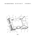
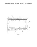
[0008] FIG. 1 is a perspective view of an article packaged for shock-protection using a plurality of thermoformed packaging devices in accordance with the present invention;
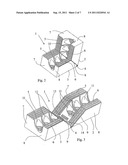
[0009] FIG. 2 is a perspective view of one of the thermoformed packaging devices according to the invention used in the arrangement of FIG. 1;
[0010] FIG. 3 is perspective view of the thermoformed packaging device of FIG. 2 when folded flat;
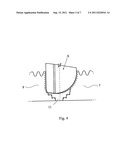
[0011] FIG. 4 is a schematic representation to an enlarged scale, illustrative of accommodation of a part of an article within the thermoformed packaging device of FIGS. 2 and 3;
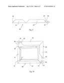
[0012] FIGS. 5 to 10 are further illustrative of the way in which thermoformed devices according to the present invention may be used for article shock-protection; and
[0013] FIG. 11 is illustrative at (a) to (c) of a three-stage sequence used for locking together components illustrated and described below with reference to FIGS. 9 and 10.
DETAILED DESCRIPTION OF THE INVENTION
[0014] Referring to FIG. 1, a large and heavy article A (depicted as a computer component in the form of a server drawer in this example) is protected for transportation and storage by four corner caps 1. Each corner cap 1 is a one-piece thermoformed molding (for example of high density polyethylene or polypropylene) that has two rectangular wings 2 and 3 and folds into the L-shape corner form. The folded and unfolded conditions of each corner cap 1 are illustrated in FIGS. 2 and 3 respectively.
[0015] Referring now also to FIGS. 2 and 3, the two wings 2 and 3 are interconnected by an integral hinge 4 and on the inside of the molding are each formed along their opposite, longitudinal margins with ridge-groove patterns 5 and 6. The longitudinal margins of each wing 2 and 3 are defined on the inside by a pair of upstanding flanges or shoulders 7 and 8 that rise to full height at 45 degrees throughout an initial, inclined portion 9 of the wing-length from the hinge 4. The ridges with intervening grooves of the patterns 5 and 6 run throughout the full length of the respective shoulders 7 and 8.
[0016] Three circular recesses 11 are located between the shoulders 7 and 8 of each wing 2 and 3. Each recess 11 is of tiered form in that its diameter decreases progressively in steps with depth to create resilient projections 12 on the outside of the molding (see FIG. 1) that afford shock-protection.
[0017] As shown most clearly in FIG. 2, the wings 2 and 3 fold towards one another on the hinge 4. This brings the two shoulders 7 and 8 of each wing 2 and 3 into abutment with the shoulders 7 and 8 respectively of the other wing, throughout their inclined portions 9 to form a miter joint. The two wings 2 and 3 now extend at right angles to one another and are locked together in this configuration by means of entry and resilient retention of a projection 13 of the wing 2 in a socket 14 of the wing 3. In addition there is interlocking in the abutting portions 9 between the ridge-groove patterns 5 and 6 of the two wings 2 and 3.
[0018] More particularly in the latter regard, the ridges and intervening grooves of each ridge-groove pattern 5 and 6 of the wing 3 are shifted laterally by one-half pitch with respect to the corresponding pattern 5 and 6 of the wing 2. As a result the abutment throughout the portions 9 of the wings 2 and 3 is with ridge-within-groove nesting of shoulder 7 with shoulder 7 and shoulder 8 with shoulder 8. This provides interlocking of the two wings 2 and 3 against relative lateral displacement and also cushioning and absorption of shock tending to close up the wings 2 and 3 further onto one another.
[0019] Each corner cap 1 fits to the periphery of the article A as illustrated in FIG. 1, with the corner of the article A received in the channel between the shoulders 7 and 8 of each wing 2 and 3. These channels are generally in mutual alignment but can be configured in the thermoforming to be adapted to the specific profile of the article A to be protected. As shown in FIGS. 2 and 3 by way of example, the channel between the shoulders 7 and 8 is configured in this case to accommodate a portion of the article A of bevelled or curved profile. This is more particularly illustrated schematically to an enlarged scale in the cross-sectional view of FIG. 4, where a profiled corner of article A is represented inserted between shoulders 7 and 8. The shoulder 7 in this case is molded with a scooped-out profile to conform closely to the profile of the article A.
[0020] Caps of the same general form (including with ridge-groove patterns corresponding to the patterns 5 and 6 in miter-joints) of the cap 1 can be utilized for protection other than in the context of corners. In this respect, reference is directed to FIG. 5 where a long, rectangular article B is protected at its corners by folded corner caps 20, and along its longer sides by identical, but unfolded, caps 20, all within a lightweight carton 21. The unfolded caps 20 give protection to the sides of the article B in the space between the folded, corner caps 20, being simply pushed onto the sides in the same way as the folded caps 20 are pushed onto the corners.
[0021] As an extension of this, a wrap for article-protection within, for example, a lightweight cardboard or other container, can be produced as illustrated in FIGS. 6 to 8 of the accompanying drawings. FIG. 6 shows in front view a thermoformed wrap 30 composed of four wings 31 to 34 that are hinged together for use in enclosing a computer monitor C to provide it with surround-protection. The base of the monitor C is first entered into the wing 32 ready for wrapping the wings 31 and 33 up round it and the wing 34 over the top to give the result illustrated by FIGS. 7 and 8.
[0022] Each of the wings 31 to 34 is molded with a configuration similar to that of each of the wings 2 and 3 of the corner caps 1 described above, but of increased length related to the breadth and height of the monitor C. The wings 31 to 34 have inclined faces at both ends so that mitered joints between them together with ridge-within-groove nesting, are established at the corners of the monitor C as the wings 31, 33 and 34 are folded up round it.
[0023] Retention of the wings 31 to 34 wrapped round the perimeter of the monitor C is by a locking tab 35 which is hinged to the free end of wing 34 and which involves a stud 36 that is entered and retained resiliently within a cavity (not shown) in the wing 31.
[0024] Where the article to be protected is very large it is often not feasible to design and manufacture a wrap capable of extending throughout the full perimeter. In these circumstances a complete peripheral wrap may be produced by assembly together end-to-end of a plurality of thermoformed wrap-components that each comprise two or more hinged wings. An example of a component 40 of this nature that is made up of just two mutually-hinged wings 41 and 42 with a locking tab 43 hinged to the wing 42, is illustrated in FIG. 9. Ridge-within-groove nesting is provided in the mitered joints between the wings 41 and 42.
[0025] FIG. 10 shows two of the components 40 in the process of being used to provide a peripheral-wrap of a television set D. The set D is shown standing in the wing 42 of the lower of the two components 40 with its left-hand side (as seen in FIG. 10) entered in the folded-up wing 41. The other component 40 is shown ready to be lowered onto the top of the set D to have the top of the set D entered in the wing 42 and its other side entered in the wing 41. Once this has been accomplished, the two components 40 are locked together using the locking tabs 43 at each of the two diagonally-opposite corners of the set D. The locking at each corner is carried out in the three-stage sequence illustrated at (a) to (c) of FIG. 11.
[0026] The three-stage locking sequence is illustrated in FIG. 11 and will be described in the context of the locking of the upper of the two corners; the locking at the other corner is carried out in a corresponding way.
[0027] Referring to stage (a) of FIG. 11, the bringing together of the wings 41 and 42 of the two components 40 respectively, is accompanied by entry of a projection 44 of the wing 41 of the lower of the two components 40 into a recess 45 in the wing 42 of the upper component 40. With the projection 44 pushed fully home within the recess 45 as illustrated for stage (b) of FIG. 11, the locking flap 43 hinged to the wing 42, is folded over to overlap the junction with the wing 41. Stage (c) of FIG. 11 illustrates the folding down of the flap 43 further to bring a projection 46 that projects from the underside of the folded-over flap 43, aligned with the projection 44 pushed into the recesses 45. More especially, the alignment brings the projection 46 facing into the reverse recess of the thermoformed projection 44. Finally, the projection 46 is pushed home into the recesses 43 for resilient retention there locking the flap 43 down and locking the two components firmly together. Retention of this condition is enhanced by virtue of the projection 46 being an interference fit with a snap action into the reverse recess; the snap action is facilitated by the resilience of the thermoformed material.
User Contributions:
Comment about this patent or add new information about this topic:
Images included with this patent application:
 |  |
 |  |
 |  |
 |
| Similar patent applications: | |
| Date | Title |
|---|---|
| 2011-09-29 | Shock-protecting packaging |
| 2009-02-12 | Environmental protection paper pulp packaging |
| 2010-12-16 | Apparatus for the protection of a package, plant, animal, or human |
| 2011-03-24 | Compositions of ethylene/vinyl acetate copolymers for heat-sealable easy opening packaging |
| 2011-03-31 | Absorbent products having improved packaging efficiency |
| New patent applications in this class: | |
| Date | Title |
|---|---|
| 2016-06-02 | Composite edge and corner protection pieces |
| 2016-04-14 | Packaging device |
| 2015-12-10 | Wedge for immobilizing objects in a box having a square or rectangular cross-section |
| 2014-12-18 | Edge protector and packaging system |
| 2014-11-20 | Apparatus for protecting electronic devices and methods of making and using the same |
| New patent applications from these inventors: | |
| Date | Title |
|---|---|
| 2015-10-15 | Packaging for a bottle |
| Top Inventors for class "Special receptacle or package" | |
| Rank | Inventor's name |
|---|---|
| 1 | Donald E. Weder |
| 2 | Brett R. Glass |
| 3 | Daniel Lee Bizzell |
| 4 | Andrea Biondi |
| 5 | Nicole E. Glass |