Patent application title: NEURON SYSTEM WITH BIO-MEDICAL UNITS
Inventors:
Ahmadreza (reza) Rofougaran (Newport Coast, CA, US)
Assignees:
BROADCOM CORPORATION
IPC8 Class: AA61N100FI
USPC Class:
607 2
Class name: Surgery: light, thermal, and electrical application light, thermal, and electrical application electrical therapeutic systems
Publication date: 2011-03-31
Patent application number: 20110077697
Inventors list |
Agents list |
Assignees list |
List by place |
Classification tree browser |
Top 100 Inventors |
Top 100 Agents |
Top 100 Assignees |
Usenet FAQ Index |
Documents |
Other FAQs |
Patent application title: NEURON SYSTEM WITH BIO-MEDICAL UNITS
Inventors:
Ahmadreza (Reza) ROFOUGARAN
Agents:
Assignees:
Origin: ,
IPC8 Class: AA61N100FI
USPC Class:
Publication date: 03/31/2011
Patent application number: 20110077697
Abstract:
An in vivo neuron system includes a plurality of bio-medical units, each
of which includes a power harvesting module, an electrical signal
detection module, and a communication module. The power harvesting module
generates a supply voltage from a wireless signal, where the supply
voltage powers the other modules. The electrical signal detection module
detects an electrical signal associated with a neuron to produce a
detected electrical signal. The communication module communicates a
representation of the detected electrical signal. Of the bio-medical
units, at least one detects an input electrical signal to the neuron and
at least another one detects the electrical signal of an axon of the
neuron.Claims:
1. An in vivo neuron system comprises:a plurality of bio-medical units,
each of the plurality of bio-medical units includes:a power harvesting
module operable to generate a supply voltage from a wireless signal
sourced from a device external to a host body;an electrical signal
detection module powered by the supply voltage and operable to detect an
electrical signal associated with a neuron to produce a detected
electrical signal; anda communication module powered by the supply
voltage and operable to communicate a representation of the detected
electrical signal, wherein:an input bio-medical unit of the plurality of
bio-medical units is operable to detect an input electrical signal to the
neuron; andan axon bio-medical unit of the plurality of bio-medical units
is operable to detect the electrical signal of an axon of the neuron.
2. The in vivo neuron system of claim 1, wherein the axon bio-medical unit further comprises:the communication module further operable to receive the representation of the detected input electrical signal from the communication module of the input bio-medical unit; anda processing module powered by the supply voltage and operable to:receive the representation of the detected input electrical signal;determine whether the representation of the detected input electrical signal corresponds to an action potential of another neuron;when the representation of the detected input electrical signal corresponds to the action potential of the other neuron, determine whether the electrical signal corresponds to an action potential of the neuron based on the action potential of the other neuron; andwhen the electrical signal does not correspond to the action potential of the neuron, determine a simulated action potential for the neuron in accordance with neural decoding; andan electrical stimulus module operable to:generate a stimulus electrical signal based on the simulated action potential; andinduce the stimulus electrical signal into the axon.
3. The in vivo neuron system of claim 1, wherein the axon bio-medical unit further comprises:the communication module further operable to receive the representation of the detected input electrical signal from the communication module of the input bio-medical unit; anda processing module powered by the supply voltage and operable to:receive the representation of the detected input electrical signal;determine whether the representation of the detected input electrical signal corresponds to an action potential of another neuron;determine whether the electrical signal corresponds to an action potential of the neuron;when the electrical signal does not correspond to the action potential of the neuron or when the representation of the detected input electrical signal does not correspond to the action potential of the other neuron, indicate a neuron communication error.
4. The in vivo neuron system of claim 1, wherein the electrical signal detection module comprises:one or more coils operable to generate a voltage based on current of the electrical signal;a transition detection circuit operable to detect transitions of the voltage;a peak detection circuit operable to detect a peak of the voltage; anda signal processing module to generate the representation of the detected electrical signal based on the transitions of the voltage and the peak of the voltage.
5. The in vivo neuron system of claim 1, wherein the electrical signal detection module comprises:a probe module operable to electrically couple to receive the electrical signal;a transition detection circuit operable to detect transitions of the voltage;a peak detection circuit operable to detect a peak of the voltage; anda signal processing module to generate the representation of the detected electrical signal based on the transitions of the voltage and the peak of the voltage.
6. The in vivo neuron system of claim 1, wherein the wireless signal comprises at least one of:a radio frequency signal;a millimeter wave signal; andan electromagnetic signal.
7. The in vivo neuron system of claim 1 further comprises at least one of:the communication module communicating the representation of the detected electrical signal with the device external to the host body; andthe communication module communicating the representation of the detected electrical signal with the other bio-medical unit.
8. A bio-medical unit for implanting into a host body comprises:a power harvesting module operable to generate a supply voltage from a wireless signal sourced from an external device to the host body;an electrical signal detection module powered by the supply voltage and operable to detect an electrical signal associated with a neuron to produce a detected electrical signal; anda communication module powered by the supply voltage and operable to communicate a representation of the detected electrical signal to the external device.
9. The bio-medical unit of claim 8 further comprises:the communication module further operable to receive a representation of a detected input electrical signal from a communication module of another bio-medical unit associated with the neuron; anda processing module powered by the supply voltage and operable to:receive the representation of the detected input electrical signal;determine whether the representation of the detected input electrical signal corresponds to an action potential of another neuron;when the representation of the detected input electrical signal corresponds to the action potential of the other neuron, determine whether the electrical signal corresponds to an action potential of the neuron based on the action potential of the other neuron; andwhen the electrical signal does not correspond to the action potential of the neuron, determine a simulated action potential for the neuron in accordance with neural decoding; andan electrical stimulus module operable to:generate a stimulus electrical signal based on the simulated action potential; andinduce the stimulus electrical signal into the axon.
10. The bio-medical unit of claim 8 further comprises:the communication module further operable to receive a representation of a detected input electrical signal from a communication module of another bio-medical unit associated with the neuron; anda processing module powered by the supply voltage and operable to:receive the representation of the detected input electrical signal;determine whether the representation of the detected input electrical signal corresponds to an action potential of another neuron;determine whether the electrical signal corresponds to an action potential of the neuron;when the electrical signal does not correspond to the action potential of the neuron or when the representation of the detected input electrical signal does not correspond to the action potential of the other neuron, indicate a neuron communication error.
11. The bio-medical unit of claim 8, wherein the electrical signal detection module comprises:one or more coils operable to generate a voltage based on current of the electrical signal;a transition detection circuit operable to detect transitions of the voltage;a peak detection circuit operable to detect a peak of the voltage; anda signal processing module to generate the representation of the detected electrical signal based on the transitions of the voltage and the peak of the voltage.
12. The bio-medical unit of claim 8, wherein the electrical signal detection module comprises:a probe module operable to electrically couple to receive the electrical signal;a transition detection circuit operable to detect transitions of the voltage;a peak detection circuit operable to detect a peak of the voltage; anda signal processing module to generate the representation of the detected electrical signal based on the transitions of the voltage and the peak of the voltage.
13. A neuron electrical bridge system comprises:an external communication device; anda plurality of bio-medical units operable to monitor electrical signals produced by a plurality of neurons, wherein:the external communication device or one of the plurality of bio-medical units detects a deviation of one of the electrical signals from an expected electrical signal based on a neuron stimulus to neuron response mapping;the external communication device determines a preceding bio-medical unit that monitoring an electrical signal preceding the one of the electrical signals and determines a following bio-medical unit that is monitoring an electrical signal following the one of the electrical signals;the preceding bio-medical unit and the following bio-medical unit establish a communication link such that the following bio-medical unit receives a representation of the electrical signal preceding the one of the electrical signals;the following bio-medical unit generates a simulated electrical signal based on the representation of the electrical signal preceding the one of the electrical signals and the neuron stimulus to neuron response mapping; andthe following bio-medical unit inputs the simulated electrical signal to a neuron of the plurality of neurons, wherein the following bio-medical unit monitors the electrical signal of the neuron.
14. The neuron electrical bridge system of claim 13, wherein each of the plurality of bio-medical units comprises:a power harvesting module operable to generate a supply voltage from a wireless signal sourced from the external communication device;an electrical signal detection module powered by the supply voltage and operable to detect the electrical signal associated with a corresponding neuron of the plurality of neurons to produce a detected electrical signal; anda communication module powered by the supply voltage and operable to communicate a representation of the detected electrical signal.
15. The neuron electrical bridge system of claim 14, wherein the electrical signal detection module comprises:one or more coils operable to generate a voltage based on current of the electrical signal;a transition detection circuit operable to detect transitions of the voltage;a peak detection circuit operable to detect a peak of the voltage; anda signal processing module to generate the representation of the detected electrical signal based on the transitions of the voltage and the peak of the voltage.
16. The neuron electrical bridge system of claim 14, wherein the electrical signal detection module comprises:a probe module operable to electrically couple to receive the electrical signal;a transition detection circuit operable to detect transitions of the voltage;a peak detection circuit operable to detect a peak of the voltage; anda signal processing module to generate the representation of the detected electrical signal based on the transitions of the voltage and the peak of the voltage.
17. The neuron electrical bridge system of claim 14, wherein the bio-medical unit further comprises:the communication module further operable to receive a representation of a detected electrical signal from a communication module of the preceding bio-medical unit; anda processing module powered by the supply voltage and operable to:receive the representation of the detected electrical signal;determine whether the representation of the detected electrical signal corresponds to an action potential of another neuron;when the representation of the detected electrical signal corresponds to the action potential of the other neuron, determine whether the electrical signal corresponds to an action potential of the neuron based on the action potential of the other neuron; andwhen the electrical signal does not correspond to the action potential of the neuron, determine a simulated action potential for the neuron in accordance with neural decoding; andan electrical stimulus module operable to:generate the stimulus electrical signal based on the simulated action potential; andinduce the stimulus electrical signal into an axon of the neuron.
Description:
CROSS REFERENCE TO RELATED APPLICATIONS
[0001]This patent application is claiming priority under 35 USC §119 to a provisionally filed patent application entitled BIO-MEDICAL UNIT AND APPLICATIONS THEREOF, having a provisional filing date of Sep. 30, 2009, and a provisional Ser. No. of 61/247,060.
STATEMENT REGARDING FEDERALLY SPONSORED RESEARCH OR DEVELOPMENT
[0002]NOT APPLICABLE
INCORPORATION-BY-REFERENCE OF MATERIAL SUBMITTED ON A COMPACT DISC
[0003]NOT APPLICABLE
BACKGROUND OF THE INVENTION
[0004]1. Technical Field of the Invention
[0005]This invention relates generally to medical equipment and more particularly to wireless medical equipment.
[0006]2. Description of Related Art
[0007]As is known, there is a wide variety of medical equipment that aids in the diagnosis, monitoring, and/or treatment of patients' medical conditions. For instances, there are diagnostic medical devices, therapeutic medical devices, life support medical devices, medical monitoring devices, medical laboratory equipment, etc. As specific exampled magnetic resonance imaging (MRI) devices produce images that illustrate the internal structure and function of a body.
[0008]The advancement of medical equipment is in step with the advancements of other technologies (e.g., radio frequency identification (RFID), robotics, etc.). Recently, RFID technology has been used for in vitro use to store patient information for easy access. While such in vitro applications have begun, the technical advancement in this area is in its infancy.
BRIEF SUMMARY OF THE INVENTION
[0009]The present invention is directed to apparatus and methods of operation that are further described in the following Brief Description of the Drawings, the Detailed Description of the Invention, and the claims. Other features and advantages of the present invention will become apparent from the following detailed description of the invention made with reference to the accompanying drawings.
BRIEF DESCRIPTION OF THE SEVERAL VIEWS OF THE DRAWING(S)
[0010]FIG. 1 is a diagram of an embodiment of a system in accordance with the present invention;
[0011]FIG. 2 is a diagram of another embodiment of a system in accordance with the present invention;
[0012]FIG. 3 is a diagram of an embodiment of an artificial body part including one or more bio-medical units in accordance with the present invention;
[0013]FIG. 4 is a schematic block diagram of an embodiment of an artificial body part in accordance with the present invention;
[0014]FIG. 5 is a diagram of another embodiment of a system in accordance with the present invention;
[0015]FIG. 6 is a diagram of another embodiment of a system in accordance with the present invention;
[0016]FIG. 7 is a diagram of another embodiment of a system in accordance with the present invention;
[0017]FIG. 8 is a schematic block diagram of an embodiment of a bio-medical unit in accordance with the present invention;
[0018]FIG. 9 is a schematic block diagram of an embodiment of a power harvesting module in accordance with the present invention;
[0019]FIG. 10 is a schematic block diagram of another embodiment of a power harvesting module in accordance with the present invention;
[0020]FIG. 11 is a schematic block diagram of another embodiment of a power harvesting module in accordance with the present invention;
[0021]FIG. 12 is a schematic block diagram of another embodiment of a power harvesting module in accordance with the present invention;
[0022]FIG. 13 is a schematic block diagram of an embodiment of a power boost module in accordance with the present invention;
[0023]FIG. 14 is a schematic block diagram of an embodiment of an electromagnetic (EM)) power harvesting module in accordance with the present invention;
[0024]FIG. 15 is a schematic block diagram of another embodiment of an electromagnetic (EM)) power harvesting module in accordance with the present invention;
[0025]FIG. 16 is a schematic block diagram of another embodiment of a bio-medical unit in accordance with the present invention;
[0026]FIG. 17 is a diagram of another embodiment of a system in accordance with the present invention;
[0027]FIG. 18 is a diagram of an example of a communication protocol within a system in accordance with the present invention;
[0028]FIG. 19 is a diagram of another embodiment of a system in accordance with the present invention;
[0029]FIG. 20 is a diagram of another example of a communication protocol within a system in accordance with the present invention;
[0030]FIG. 21 is a diagram of an embodiment of a network of bio-medical units in accordance with the present invention;
[0031]FIG. 22 is a logic diagram of an embodiment of a method for bio-medical unit communications in accordance with the present invention;
[0032]FIG. 23 is a diagram of an embodiment of a network of bio-medical units that include MEMS robotics in accordance with the present invention;
[0033]FIG. 24 is a diagram of another embodiment of a network of bio-medical units that include MEMS robotics in accordance with the present invention;
[0034]FIG. 25 is a diagram of an embodiment of a bio-medical unit collecting image data in accordance with the present invention;
[0035]FIG. 26 is a diagram of an embodiment of a network of bio-medical units for facilitating electrical stimulus treatment in accordance with the present invention;
[0036]FIG. 27 is a diagram of an embodiment of power conversion modules in a bio-medical unit of FIG. 26 in accordance with the present invention;
[0037]FIG. 28 is a diagram of an embodiment of a bio-medical unit including sampling modules in accordance with the present invention;
[0038]FIG. 29 is a diagram of another embodiment of a network of bio-medical units facilitating detecting of electrical impulses in accordance with the present invention;
[0039]FIG. 30 is a diagram of another embodiment of a bio-medical unit in accordance with the present invention;
[0040]FIG. 31 is a diagram of an embodiment of a neuron system that includes a plurality of bio-medical units in accordance with the present invention;
[0041]FIG. 32 is a diagram of an embodiment of an electrical signal detection module in accordance with the present invention;
[0042]FIG. 33 is a diagram of another embodiment of an electrical signal detection module in accordance with the present invention;
[0043]FIG. 34 is a diagram of another embodiment of a neuron system that includes a plurality of bio-medical units in accordance with the present invention; and
[0044]FIG. 35 is a diagram of an embodiment of bio-medical unit communication within a neuron system in accordance with the present invention.
DETAILED DESCRIPTION OF THE INVENTION
[0045]FIG. 1 is a diagram of an embodiment of a system that includes a plurality of bio-medical units 10 embedded within a body and/or placed on the surface of the body to facilitate diagnosis, treatment, and/or data collections. Each of the bio-medical units 10 is a passive device (e.g., it does not include a power source (e.g., a battery)) and, as such, includes a power harvesting module. The bio-medical units 10 may also include one or more of memory, a processing module, and functional modules. Alternatively, or in addition to, each of the bio-medical units 10 may include a rechargeable power source.
[0046]In operation, a transmitter 12 emits electromagnetic signals 16 that pass through the body and are received by a receiver 14. The transmitter 12 and receiver 14 may be part of a piece of medical diagnostic equipment (e.g., magnetic resonance imaging (MRI), X-ray, etc.) or independent components for stimulating and communicating with the network of bio-medical units in and/or on a body. One or more of the bio-medical units 10 receives the transmitted electromagnetic signals 16 and generates a supply voltage therefrom. Examples of this will be described in greater detail with reference to FIGS. 8-12.
[0047]Embedded within the electromagnetic signals 16 (e.g., radio frequency (RF) signals, millimeter wave (MMW) signals, MRI signals, etc.) or via separate signals, the transmitter 12 communicates with one or more of the bio-medical units 10. For example, the electromagnetic signals 16 may have a frequency in the range of a few MHz to 900 MHz and the communication with the bio-medical units 10 is modulated on the electromagnetic signals 16 at a much higher frequency (e.g., 5 GHz to 300 GHz). As another example, the communication with the bio-medical units 10 may occur during gaps (e.g., per protocol of medical equipment or injected for communication) of transmitting the electromagnetic signals 16. As another example, the communication with the bio-medical units 10 occurs in a different frequency band and/or using a different transmission medium (e.g., use RF or MMW signals when the magnetic field of the electromagnetic signals are dominate, use ultrasound signals when the electromagnetic signals 16 are RF and/or MMW signals, etc.).
[0048]One or more of the bio-medical units 10 receives the communication signals 18 and processes them accordingly. The communication signals 18 may be instructions to collect data, to transmit collected data, to move the unit's position in the body, to perform a function, to administer a treatment, etc. If the received communication signals 18 require a response, the bio-medical unit 10 prepares an appropriate response and transmits it to the receiver 14 using a similar communication convention used by the transmitter 12.
[0049]FIG. 2 is a diagram of another embodiment of a system that includes a plurality of bio-medical units 10 embedded within a body and/or placed on the surface of the body to facilitate diagnosis, treatment, and/or data collections. Each of the bio-medical units 10 is a passive device and, as such, includes a power harvesting module. The bio-medical units 10 may also include one or more of memory, a processing module, and functional modules. In this embodiment, the person is placed in an MRI machine (fixed or portable) that generates a magnetic field 26 through which the MRI transmitter 20 transmits MRI signals 28 to the MRI receiver 22.
[0050]One or more of the bio-medical units 10 powers itself by harvesting energy from the magnetic field 26 or changes thereof as produced by gradient coils, from the magnetic fields of the MRI signals 28, from the electrical fields of the MRI signals 28, and/or from the electromagnetic aspects of the MRI signals 28. A unit 10 converts the harvested energy into a supply voltage that supplies other components of the unit (e.g., a communication module, a processing module, memory, a functional module, etc.).
[0051]A communication device 24 communicates data and/or control communications 30 with one or more of the bio-medical units 10 over one or more wireless links. The communication device 24 may be a separate device from the MRI machine or integrated into the MRI machine. For example, the communication device 24, whether integrated or separate, may be a cellular telephone, a computer with a wireless interface (e.g., a WLAN station and/or access point, Bluetooth, a proprietary protocol, etc.), etc. A wireless link may be one or more frequencies in the ISM band, in the 60 GHz frequency band, the ultrasound frequency band, and/or other frequency bands that supports one or more communication protocols (e.g., data modulation schemes, beamforming, RF or MMW modulation, encoding, error correction, etc.).
[0052]The composition of the bio-medical units 10 includes non-ferromagnetic materials (e.g., paramagnetic or diamagnetic) and/or metal alloys that are minimally affected by an external magnetic field 26. In this regard, the units harvest power from the MRI signals 28 and communicate using RF and/or MMW electromagnetic signals with negligible chance of encountering the projectile or missile effect of implants that include ferromagnetic materials.
[0053]FIG. 3 is a diagram of an embodiment of an artificial body part 32 including one or more bio-medical units 10 that may be surgically implanted into a body. The artificial body part 32 may be a pace maker, a breast implant, a joint replacement, an artificial bone, splints, fastener devices (e.g., screws, plates, pins, sutures, etc.), artificial organ, etc. The artificial body part 32 may be permanently embedded in the body or temporarily embedded into the body.
[0054]FIG. 4 is a schematic block diagram of an embodiment of an artificial body part 32 that includes one or more bio-medical units 10. For instance, one bio-medical unit 10 may be used to detect infections, the body's acceptance of the artificial body part 32, measure localized body temperature, monitor performance of the artificial body part 32, and/or data gathering for other diagnostics. Another bio-medical unit 10 may be used for deployment of treatment (e.g., disperse medication, apply electrical stimulus, apply RF radiation, apply laser stimulus, etc.). Yet another bio-medical unit 10 may be used to adjust the position of the artificial body part 32 and/or a setting of the artificial body part 32. For example, a bio-medical unit 10 may be used to mechanically adjust the tension of a splint, screws, etc. As another example, a bio-medical unit 10 may be used to adjust an electrical setting of the artificial body part 32.
[0055]FIG. 5 is a diagram of another embodiment of a system that includes a plurality of bio-medical units 10 and one or more communication devices 24 coupled to a wide area network (WAN) communication device 34 (e.g., a cable modem, DSL modem, base station, access point, hot spot, etc.). The WAN communication device 34 is coupled to a network 42 (e.g., cellular telephone network, internet, etc.), which has coupled to it a plurality of remote monitors 36, a plurality of databases 40, and a plurality of computers 38. The communication device 24 includes a processing module and a wireless transceiver module (e.g., one or more transceivers) and may function similarly to communication module 48 as described in FIG. 8,
[0056]In this system, one or more bio-medical units 10 are implanted in, or affixed to, a host body (e.g., a person, an animal, genetically grown tissue, etc.). As previously discussed and will be discussed in greater detail with reference to one or more of the following figures, a bio-medical unit includes a power harvesting module, a communication module, and one or more functional modules. The power harvesting module operable to produce a supply voltage from a received electromagnetic power signal (e.g., the electromagnetic signal 16 of FIGS. 1 and 2, the MRI signals of one or more the subsequent figures). The communication module and the at least one functional module are powered by the supply voltage.
[0057]In an example of operation, the communication device 24 (e.g., integrated into an MRI machine, a cellular telephone, a computer with a wireless interface, etc.) receives a downstream WAN signal from the network 42 via the WAN communication device 34. The downstream WAN signal may be generated by a remote monitoring device 36, a remote diagnostic device (e.g., computer 38 performing a remote diagnostic function), a remote control device (e.g., computer 38 performing a remote control function), and/or a medical record storage device (e.g., database 40).
[0058]The communication device 24 converts the downstream WAN signal into a downstream data signal. For example, the communication device 24 may convert the downstream WAN signal into a symbol stream in accordance with one or more wireless communication protocols (e.g., GSM, CDMA, WCDMA, HSUPA, HSDPA, WiMAX, EDGE, GPRS, IEEE 802.11, Bluetooth, ZigBee, universal mobile telecommunications system (UMTS), long term evolution (LTE), IEEE 802.16, evolution data optimized (EV-DO), etc.). The communication device 24 may convert the symbol stream into the downstream data signal using the same or a different wireless communication protocol.
[0059]Alternatively, the communication device 24 may convert the symbol stream into data that it interprets to determine how to structure the communication with the bio-medical unit 10 and/or what data (e.g., instructions, commands, digital information, etc.) to include in the downstream data signal. Having determined how to structure and what to include in the downstream data signal, the communication device 24 generates the downstream data signal in accordance with one or more wireless communication protocols. As yet another alternative, the communication device 24 may function as a relay, which provides the downstream WAN signal as the downstream data signal to the one or more bio-medical units 10.
[0060]When the communication device 24 has (and/or is processing) the downstream data signal to send to the bio-medical unit, it sets up a communication with the bio-medical unit. The set up may include identifying the particular bio-medical unit(s), determining the communication protocol used by the identified bio-medical unit(s), sending a signal to an electromagnetic device (e.g., MRI device, etc.) to request that it generates the electromagnetic power signal to power the bio-medical unit, and/or initiate a communication in accordance with the identified communication protocol. As an alternative to requesting a separate electromagnetic device to create the electromagnetic power signal, the communication device may include an electromagnetic device to create the electromagnetic power signal.
[0061]Having set up the communication, the communication device 24 wirelessly communicates the downstream data signal to the communication module of the bio-medical unit 10. The functional module of the bio-medical unit 10 processes the downstream data contained in the downstream data signal to perform a bio-medical functional, to store digital information contained in the downstream data, to administer a treatment (e.g., administer a medication, apply laser stimulus, apply electrical stimulus, etc.), to collect a sample (e.g., blood, tissue, cell, etc.), to perform a micro electro-mechanical function, and/or to collect data. For example, the bio-medical function may include capturing a digital image, capturing a radio frequency (e.g., 300 MHz to 300 GHz) radar image, an ultrasound image, a tissue sample, and/or a measurement (e.g., blood pressure, temperature, pulse, blood-oxygen level, blood sugar level, etc.).
[0062]When the downstream data requires a response, the functional module performs a bio-medical function to produce upstream data. The communication module converts the upstream data into an upstream data signal in accordance with the one or more wireless protocols. The communication device 24 converts the upstream data signal into an upstream wide area network (WAN) signal and transmits it to a remote diagnostic device, a remote control device, and/or a medical record storage device. In this manner, a person(s) operating the remote monitors 36 may view images and/or the data 30 gathered by the bio-medical units 10. This enables a specialist to be consulted without requiring the patient to travel to the specialist's office.
[0063]In another example of operation, one or more of the computers 38 may communicate with the bio-medical units 10 via the communication device 24, the WAN communication device 34, and the network 42. In this example, the computer 36 may provide commands 30 to one or more of the bio-medical units 10 to gather data, to dispense a medication, to move to a new position in the body, to perform a mechanical function (e.g., cut, grasp, drill, puncture, stitch, patch, etc.), etc. As such, the bio-medical units 10 may be remotely controlled via one or more of the computers 36.
[0064]In another example of operation, one or more of the bio-medical units 10 may read and/or write data from or to one or more of the databases 40. For example, data (e.g., a blood sample analysis) generated by one or more of the bio-medical units 10 may be written to one of the databases 40. The communication device 24 and/or one of the computers 36 may control the writing of data to or the reading of data from the database(s) 40. The data may further include medical records, medical images, prescriptions, etc.
[0065]FIG. 6 is a diagram of another embodiment of a system that includes a plurality of bio-medical units 10. In this embodiment, the bio-medical units 10 can communicate with each other directly and/or communicate with the communication device 24 directly. The communication medium may be an infrared channel(s), an RF channel(s), a MMW channel(s), and/or ultrasound. The units may use a communication protocol such as token passing, carrier sense, time division multiplexing, code division multiplexing, frequency division multiplexing, etc.
[0066]FIG. 7 is a diagram of another embodiment of a system that includes a plurality of bio-medical units 10. In this embodiment, one of the bio-medical units 44 functions as an access point for the other units. As such, the designated unit 44 routes communications between the units 10 and between one or more units 10 and the communication device 24. The communication medium may be an infrared channel(s), an RF channel(s), a MMW channel(s), and/or ultrasound. The units 10 may use a communication protocol such as token passing, carrier sense, time division multiplexing, code division multiplexing, frequency division multiplexing, etc.
[0067]FIG. 8 is a schematic block diagram of an embodiment of a bio-medical unit 10 that includes a power harvesting module 46, a communication module 48, a processing module 50, memory 52, and one or more functional modules 54. The processing module 50 may be a single processing device or a plurality of processing devices. Such a processing device may be a microprocessor, micro-controller, digital signal processor, microcomputer, central processing unit, field programmable gate array, programmable logic device, state machine, logic circuitry, analog circuitry, digital circuitry, and/or any device that manipulates signals (analog and/or digital) based on hard coding of the circuitry and/or operational instructions. The processing module 50 may have an associated memory 52 and/or memory element, which may be a single memory device, a plurality of memory devices, and/or embedded circuitry of the processing module. Such a memory device 52 may be a read-only memory, random access memory, volatile memory, non-volatile memory, static memory, dynamic memory, flash memory, cache memory, and/or any device that stores digital information. Note that if the processing module 50 includes more than one processing device, the processing devices may be centrally located (e.g., directly coupled together via a wired and/or wireless bus structure) or may be distributedly located (e.g., cloud computing via indirect coupling via a local area network and/or a wide area network). Further note that when the processing module 50 implements one or more of its functions via a state machine, analog circuitry, digital circuitry, and/or logic circuitry, the memory and/or memory element storing the corresponding operational instructions may be embedded within, or external to, the circuitry comprising the state machine, analog circuitry, digital circuitry, and/or logic circuitry. Still further note that, the memory element stores, and the processing module executes, hard coded and/or operational instructions corresponding to at least some of the steps and/or functions illustrated in FIGS. 1-26.
[0068]The power harvesting module 46 may generate one or more supply voltages 56 (Vdd) from a power source signal (e.g., one or more of MRI electromagnetic signals 16, magnetic fields 26, RF signals, MMW signals, ultrasound signals, light signals, and body motion). The power harvesting module 46 may be implemented as disclosed in U.S. Pat. No. 7,595,732 to generate one or more supply voltages from an RF signal. The power harvesting module 46 may be implemented as shown in one or more FIGS. 9-11 to generate one or more supply voltages 56 from an MRI signal 28 and/or magnetic field 26. The power harvesting module 46 may be implemented as shown in FIG. 12 to generate one or more supply voltage 56 from body motion. Regardless of how the power harvesting module generates the supply voltage(s), the supply voltage(s) are used to power the communication module 48, the processing module 50, the memory 52, and/or the functional modules 54.
[0069]In an example of operation, a receiver section of the communication module 48 receives an inbound wireless communication signal 60 and converts it into an inbound symbol stream. For example, the receiver section amplifies an inbound wireless (e.g., RF or MMW) signal 60 to produce an amplified inbound RF or MMW signal. The receiver section may then mix in-phase (I) and quadrature (Q) components of the amplified inbound RF or MMW signal with in-phase and quadrature components of a local oscillation to produce a mixed I signal and a mixed Q signal. The mixed I and Q signals are combined to produce an inbound symbol stream. In this embodiment, the inbound symbol may include phase information (e.g., +/-Δθ [phase shift] and/or θ(t) [phase modulation]) and/or frequency information (e.g., +/-Δf [frequency shift] and/or f(t) [frequency modulation]). In another embodiment and/or in furtherance of the preceding embodiment, the inbound RF or MMW signal includes amplitude information (e.g., +/-ΔA [amplitude shift] and/or A(t) [amplitude modulation]). To recover the amplitude information, the receiver section includes an amplitude detector such as an envelope detector, a low pass filter, etc.
[0070]The processing module 50 converts the inbound symbol stream into inbound data and generates a command message based on the inbound data. The command message may instruction one or more of the functional modules to perform one or more electro-mechanical functions of gathering data (e.g., imaging data, flow monitoring data), dispensing a medication, moving to a new position in the body, performing a mechanical function (e.g., cut, grasp, drill, puncture, stitch, patch, etc.), dispensing a treatment, collecting a biological sample, etc.
[0071]To convert the inbound symbol stream into the inbound data (e.g., voice, text, audio, video, graphics, etc.), the processing module 50 may perform one or more of: digital intermediate frequency to baseband conversion, time to frequency domain conversion, space-time-block decoding, space-frequency-block decoding, demodulation, frequency spread decoding, frequency hopping decoding, beamforming decoding, constellation demapping, deinterleaving, decoding, depuncturing, and/or descrambling. Such a conversion is typically prescribed by one or more wireless communication standards (e.g., GSM, CDMA, WCDMA, HSUPA, HSDPA, WiMAX, EDGE, GPRS, IEEE 802.11, Bluetooth, ZigBee, universal mobile telecommunications system (UMTS), long term evolution (LTE), IEEE 802.16, evolution data optimized (EV-DO), etc.).
[0072]The processing module 50 provides the command message to one or more of the micro-electromechanical functional modules 54. The functional module 54 performs an electro-mechanical function within a hosting body in accordance with the command message. Such an electro-mechanical function includes at least one of data gathering (e.g., image, flow monitoring), motion, repairs, dispensing medication, biological sampling, diagnostics, applying laser treatment, applying ultrasound treatment, grasping, sawing, drilling, providing an electronic stimulus etc. Note that the functional modules 54 may be implemented using nanotechnology and/or microelectronic mechanical systems (MEMS) technology.
[0073]When requested per the command message (e.g. gather data and report the data), the micro electro-mechanical functional module 54 generates an electro-mechanical response based on the performing the electro-mechanical function. For example, the response may be data (e.g., heart rate, blood sugar levels, temperature, blood flow rate, image of a body object, etc.), a biological sample (e.g., blood sample, tissue sample, etc.), acknowledgement of performing the function (e.g., acknowledge a software update, storing of data, etc.), and/or any appropriate response. The micro electro-mechanical functional module 54 provides the response to the processing module 50.
[0074]The processing module 50 converts the electro-mechanical response into an outbound symbol stream, which may be done in accordance with one or more wireless communication standards (e.g., GSM, CDMA, WCDMA, HSUPA, HSDPA, WiMAX, EDGE, GPRS, IEEE 802.11, Bluetooth, ZigBee, universal mobile telecommunications system (UMTS), long term evolution (LTE), IEEE 802.16, evolution data optimized (EV-DO), etc.). Such a conversion includes one or more of: scrambling, puncturing, encoding, interleaving, constellation mapping, modulation, frequency spreading, frequency hopping, beamforming, space-time-block encoding, space-frequency-block encoding, frequency to time domain conversion, and/or digital baseband to intermediate frequency conversion.
[0075]A transmitter section of the communication module 48 converts an outbound symbol stream into an outbound RF or MMW signal 60 that has a carrier frequency within a given frequency band (e.g., 900 MHz, 2.5 GHz, 5 GHz, 57-66 GHz, etc.). In an embodiment, this may be done by mixing the outbound symbol stream with a local oscillation to produce an up-converted signal. One or more power amplifiers and/or power amplifier drivers amplifies the up-converted signal, which may be RF or MMW bandpass filtered, to produce the outbound RF or MMW signal 60. In another embodiment, the transmitter section includes an oscillator that produces an oscillation. The outbound symbol stream provides phase information (e.g., +/-Δθ [phase shift] and/or θ(t) [phase modulation]) that adjusts the phase of the oscillation to produce a phase adjusted RF or MMW signal, which is transmitted as the outbound RF signal 60. In another embodiment, the outbound symbol stream includes amplitude information (e.g., A(t) [amplitude modulation]), which is used to adjust the amplitude of the phase adjusted RF or MMW signal to produce the outbound RF or MMW signal 60.
[0076]In yet another embodiment, the transmitter section includes an oscillator that produces an oscillation. The outbound symbol provides frequency information (e.g., +/-Δf [frequency shift] and/or f(t) [frequency modulation]) that adjusts the frequency of the oscillation to produce a frequency adjusted RF or MMW signal, which is transmitted as the outbound RF or MMW signal 60. In another embodiment, the outbound symbol stream includes amplitude information, which is used to adjust the amplitude of the frequency adjusted RF or MMW signal to produce the outbound RF or MMW signal 60. In a further embodiment, the transmitter section includes an oscillator that produces an oscillation. The outbound symbol provides amplitude information (e.g., +/-ΔA [amplitude shift] and/or A(t) [amplitude modulation) that adjusts the amplitude of the oscillation to produce the outbound RF or MMW signal 60.
[0077]Note that the bio-medical unit 10 may be encapsulated by an encapsulate 58 that is non-toxic to the body. For example, the encapsulate 58 may be a silicon based product, a non-ferromagnetic metal alloy (e.g., stainless steel), etc. As another example, the encapsulate 58 may include a spherical shape and have a ferromagnetic liner that shields the unit from a magnetic field and to offset the forces of the magnetic field. Further note that the bio-medical unit 10 may be implemented on a single die that has an area of a few millimeters or less. The die may be fabricated in accordance with CMOS technology, Gallium-Arsenide technology, and/or any other integrated circuit die fabrication process.
[0078]In another example of operation, one of the functional modules 54 functions as a first micro-electro mechanical module and another one of the functions modules 54 functions as a second micro-electro mechanical module. In this example, the bio-medical unit is implanted into a host body (e.g., a person, an animal, a reptile, etc.) at a position proximal to a body object to be monitored and/or have an image taken thereof. For example, the body object may be a vein, an artery, an organ, a cyst (or other growth), etc. As a specific example, the bio-medical unit may be positioned approximately parallel to the flow of blood in a vein, artery, and/or the heart.
[0079]When powered by the supply voltage, the first micro-electro mechanical module generates and transmits a wireless signal at, or around, the body object. The second micro-electro mechanical module receives a representation of the wireless signal (e.g., a reflection of the wireless signal, a refraction of the wireless signal, or a determined absorption of the wireless signal). Note that the wireless signal may be an ultrasound signal, a radio frequency signal, and/or a millimeter wave signal.
[0080]The processing module 50 may coordinate the transmitting of the wireless signal and the receiving of the representation of the wireless signal. For example, the processing module may receive, via the communication module, a command to enable the transmitting of the wireless signal (e.g., an ultrasound signal) and the receiving of the representation of the wireless signal. In response, the processing module generates a control signal that it provides to the first micro-electro mechanical module to enable it to transmit the wireless signal.
[0081]In addition, the processing module may generate flow monitoring data based on the second micro-electro mechanical module receiving of the representation of the wireless signal. As a specific example, the processing module calculates a fluid flow rate based on phase shifting and/or frequency shifting between the transmitting of the wireless signal and the receiving of the representation of the wireless signal. As another specific example, the processing module gathers phase shifting data and/or frequency shifting data based on the transmitting of the wireless signal and the receiving of the representation of the wireless signal.
[0082]The processing module may further generate imaging data based on the second micro-electro mechanical module receiving the representation of the wireless signal. As a specific example, the processing module calculates an image of the body object based absorption of the wireless signal by the body object and/or vibration of the body object. As another specific example, the processing module gathers data regarding the absorption of the wireless signal by the body object and/or of the vibration of the body object.
[0083]While the preceding examples of a bio-medical unit including first and second micro-electro mechanical modules for transmitting and receiving wireless signals (e.g., ultrasound, RF, MMW, etc.), a bio-medical unit may include one or the other module. For example, a bio-medical unit may include a micro-electro mechanical module for transmitting a wireless signal, where the receiver is external to the body or in another bio-medical unit. As another example, a bio-medical unit may include a micro-electro mechanical module for receiving a representation of a wireless signal, where the transmitter is external to the body or another bio-medical unit.
[0084]FIG. 9 is a schematic block diagram of an embodiment of a power harvesting module 46 that includes an array of on-chip air core inductors 64, a rectifying circuit 66, capacitors, and a regulation circuit 68. The inductors 64 may each having an inductance of a few nano-Henries to a few micro-Henries and may be coupled in series, in parallel, or a series parallel combination.
[0085]In an example of operation, the MRI transmitter 20 transmits MRI signals 28 at a frequency of 3-45 MHz at a power level of up to 35 KWatts. The air core inductors 64 are electromagnetically coupled to generate a voltage from the magnetic and/or electric field generated by the MRI signals 28. Alternatively, or in addition to, the air core inductors 64 may generate a voltage from the magnetic field 26 and changes thereof produced by the gradient coils. The rectifying circuit 66 rectifies the AC voltage produced by the inductors to produce a first DC voltage. The regulation circuit generates one or more desired supply voltages 56 from the first DC voltage.
[0086]The inductors 64 may be implemented on one more metal layers of the die and include one or more turns per layer. Note that trace thickness, trace length, and other physical properties affect the resulting inductance.
[0087]FIG. 10 is a schematic block diagram of another embodiment of a power harvesting module 46 that includes a plurality of on-chip air core inductors 70, a plurality of switching units (S), a rectifying circuit 66, a capacitor, and a switch controller 72. The inductors 70 may each having an inductance of a few nano-Henries to a few micro-Henries and may be coupled in series, in parallel, or a series parallel combination.
[0088]In an example of operation, the MRI transmitter 20 transmits MRI signals 28 at a frequency of 3-45 MHz at a power level of up to 35 KWatts. The air core inductors 70 are electromagnetically coupled to generate a voltage from the magnetic and/or electric field generated by the MRI signals 28. The switching module 72 engages the switches via control signals 74 to couple the inductors 70 in series and/or parallel to generate a desired AC voltage. The rectifier circuit 66 and the capacitor(s) convert the desired AC voltage into the one or more supply voltages 56.
[0089]FIG. 11 is a schematic block diagram of another embodiment of a power harvesting module 46 that includes a plurality of Hall effect devices 76, a power combining module 78, and a capacitor(s). In an example of operation, the Hall effect devices 76 generate a voltage based on the constant magnetic field (H) and/or a varying magnetic field. The power combining module 78 (e.g., a wire, a switch network, a transistor network, a diode network, etc.) combines the voltages of the Hall effect devices 76 to produce the one or more supply voltages 56.
[0090]FIG. 12 is a schematic block diagram of another embodiment of a power harvesting module 46 that includes a plurality of piezoelectric devices 82, a power combining module 78, and a capacitor(s). In an example of operation, the piezoelectric devices 82 generate a voltage based on body movement, ultrasound signals, movement of body fluids, etc. The power combining module 78 (e.g., a wire, a switch network, a transistor network, a diode network, etc.) combines the voltages of the Hall effect devices 82 to produce the one or more supply voltages 56. Note that the piezoelectric devices 82 may include one or more of a piezoelectric motor, a piezoelectric actuator, a piezoelectric sensor, and/or a piezoelectric high voltage device.
[0091]The various embodiments of the power harvesting module 46 may be combined to generate more power, more supply voltages, etc. For example, the embodiment of FIG. 9 may be combined with one or more of the embodiments of FIGS. 11 and 12.
[0092]FIG. 13 is a schematic block diagram of an embodiment of a power boost module 84 that harvests energy from MRI signals 28 and converts the energy into continuous wave (CW) RF (e.g., up to 3 GHz) and/or MMW (e.g., up to 300 GHz) signals 92 to provide power to the implanted bio-medical units 10. The power boost module 84 sits on the body of the person under test or treatment and includes an electromagnetic power harvesting module 86 and a continuous wave generator 88. In such an embodiment, the power boosting module 84 can recover significantly more energy than a bio-medical unit 10 since it can be significantly larger. For example, a bio-medical unit 10 may have an area of a few millimeters squared while the power boosting module 84 may have an area of a few to tens of centimeters squared.
[0093]FIG. 14 is a schematic block diagram of an embodiment of an electromagnetic (EM)) power harvesting module 86 that includes inductors, diodes (or transistors) and a capacitor. The inductors may each be a few mili-Henries such that the power boost module can deliver up to 10's of mili-watts of power.
[0094]FIG. 15 is a schematic block diagram of another embodiment of an electromagnetic (EM)) power harvesting module 86 that includes a plurality of Hall effect devices 76, a power combining module 78, and a capacitor. This functions as described with reference to FIG. 11, but the Hall effect devices 76 can be larger such that more power can be produced. Note that the EM power harvesting module 86 may include a combination of the embodiment of FIG. 14 and the embodiment of FIG. 15.
[0095]FIG. 16 is a schematic block diagram of another embodiment of a bio-medical unit 10 that includes a power harvesting module 46, a communication module 48, a processing module 50, memory 52, and may include one or more functional modules 54 and/or a Hall effect communication module 116. The communication module 48 may include one or more of an ultrasound transceiver 118 (i.e., a receiver and a transmitter), an electromagnetic transceiver 122, an RF and/or MMW transceiver 120, and a light source (LED) transceiver 124. Note that examples of the various types of communication modules 48 will be described in greater detail with reference to one or more of the subsequent Figures.
[0096]The one or more functional modules 54 may perform a repair function, an imaging function, and/or a leakage detection function, which may utilize one or more of a motion propulsion module 96, a camera module 98, a sampling robotics module 100, a treatment robotics module 102, an accelerometer module 104, a flow meter module 106, a transducer module 108, a gyroscope module 110, a high voltage generator module 112, a control release robotics module 114, and/or other functional modules described with reference to one or more other figures. The functional modules 54 may be implemented using MEMS technology and/or nanotechnology. For example, the camera module 98 may be implemented as a digital image sensor in MEMS technology.
[0097]The Hall effect communication module 116 utilizes variations in the magnetic field and/or electrical field to produce a plus or minus voltage, which can be encoded to convey information. For example, the charge applied to one or more Hall effect devices 76 may be varied to produce the voltage change. As another example, an MRI transmitter 20 and/or gradient unit may modulate a signal on the magnetic field 26 it generates to produce variations in the magnetic field 26.
[0098]FIG. 17 is a diagram of another embodiment of a system that includes one or more bio-medical units 10, a transmitter unit 126, and a receiver unit 128. Each of the bio-medical units 10 includes a power harvesting module 46, a MMW transceiver 138, a processing module 50, and memory 52. The transmitter unit 126 includes a MRI transmitter 130 and a MMW transmitter 132. The receiver unit 128 includes a MRI receiver 134 and a MMW receiver 136. Note that the MMW transmitter 132 and MMW receiver 136 may be in the same unit (e.g., in the transmitter unit, in the receiver unit, or housed in a separate device).
[0099]In an example of operation, the bio-medical unit 10 recovers power from the electromagnetic (EM) signals 146 transmitted by the MRI transmitter 130 and communicates via MMW signals 148-150 with the MMW transmitter 132 and MMW receiver 136. The MRI transmitter 130 may be part of a portable MRI device, may be part of a full sized MRI machine, and/or part of a separate device for generating EM signals 146 for powering the bio-medical unit 10.
[0100]FIG. 18 is a diagram of an example of a communication protocol within the system of FIG. 17. In this diagram, the MRI transmitter 20 transmits RF signals 152, which have a frequency in the range of 3-45 MHz, at various intervals with varying signal strengths. The power harvesting module 46 of the bio-medical units 10 may use these signals to generate power for the bio-medical unit 10.
[0101]In addition to the MRI transmitter 20 transmitting its signal, a constant magnetic field and various gradient magnetic fields 154-164 are created (one or more in the x dimension Gx, one or more in the y dimension Gy, and one or more in the z direction Gz). The power harvesting module 46 of the bio-medical unit 10 may further use the constant magnetic field and/or the varying magnetic fields 154-164 to create power for the bio-medical unit 10.
[0102]During non-transmission periods of the cycle, the bio-medical unit 10 may communicate 168 with the MMW transmitter 132 and/or MMW receiver 136. In this regard, the bio-medical unit 10 alternates from generating power to MMW communication in accordance with the conventional transmission-magnetic field pattern of an MRI machine.
[0103]FIG. 19 is a diagram of another embodiment of a system includes one or more bio-medical units 10, a transmitter unit 126, and a receiver unit 128. Each of the bio-medical units 10 includes a power harvesting module 46, an EM transceiver 174, a processing module 50, and memory 52. The transmitter unit 126 includes a MRI transmitter 130 and electromagnetic (EM) modulator 170. The receiver unit 128 includes a MRI receiver 134 and an EM demodulator 172. The transmitter unit 126 and receiver unit 128 may be part of a portable MRI device, may be part of a full sized MRI machine, or part of a separate device for generating EM signals for powering the bio-medical unit 10.
[0104]In an example of operation, the MRI transmitter 130 generates an electromagnetic signal that is received by the EM modulator 170. The EM modulator 170 modulates a communication signal on the EM signal to produce an inbound modulated EM signal 176. The EM modulator 170 may modulate (e.g., amplitude modulation, frequency modulation, amplitude shift keying, frequency shift keying, etc.) the magnetic field and/or electric field of the EM signal. In another embodiment, the EM modulator 170 may modulate the magnetic fields produced by the gradient coils to produce the inbound modulated EM signals 176.
[0105]The bio-medical unit 10 recovers power from the modulated electromagnetic (EM) signals. In addition, the EM transceiver 174 demodulates the modulated EM signals 178 to recover the communication signal. For outbound signals, the EM transceiver 174 modulates an outbound communication signal to produce outbound modulated EM signals 180. In this instance, the EM transceiver 174 is generating an EM signal that, in air, is modulated on the EM signal transmitted by the transmitter unit 126. In one embodiment, the communication in this system is half duplex such that the modulation of the inbound and outbound communication signals is at the same frequency. In another embodiment, the modulation of the inbound and outbound communication signals are at different frequencies to enable full duplex communication.
[0106]FIG. 20 is a diagram of another example of a communication protocol within the system of FIG. 19. In this diagram, the MRI transmitter 20 transmits RF signals 152, which have a frequency in the range of 3-45 MHz, at various intervals with varying signal strengths. The power harvesting module 46 of the bio-medical units 10 may use these signals to generate power for the bio-medical unit 10.
[0107]In addition to the MRI transmitter 20 transmitting its signal, a constant magnetic field and various gradient magnetic fields are created 154-164 (one or more in the x dimension Gx, one or more in the y dimension Gy, and one or more in the z direction Gz). The power harvesting module 46 of the bio-medical unit 10 may further use the constant magnetic field and/or the varying magnetic fields 154-164 to create power for the bio-medical unit 10.
[0108]During the transmission periods of the cycle, the bio-medical unit 10 may communicate via the modulated EM signals 182. In this regard, the bio-medical unit 10 generates power and communicates in accordance with the conventional transmission-magnetic field pattern of an MRI machine.
[0109]FIG. 21 is a schematic block diagram of an embodiment of networked bio-medical units 10 that communicate with each other, perform sensing functions to produce sensed data 218-232, process the sensed data to produce processed data, and transmit the processed data 216. The bio-medical units 10 may be positioned in a body part to sense data across the body part and to transmit data to an external communication device. The transmitted data may be further processed or aggregated from sensed data.
[0110]The bio-medical units 10 may monitor various types of biological functions over a short term or a long term to produce the sensed data 218-232. Note that the sensed data 218-232 may include blood flow rate, blood pressure, temperature, air flow, blood oxygen level, density, white cell count, red cell count, position information, etc.
[0111]The bio-medical unit 10 establishes communications with one or more other bio-medical units 10 to facilitate the communication of sensed data 218-232 and processed data 216. The communication may include EM signals, MMW signals, optical signals, sound signals, and/or RF signals.
[0112]The bio-medical unit 10 may determine position information based on the sensed data 218-232 and include the position information in the communication. The bio-medical unit 10 may also determine a mode of operation based on one or more of a command, a list, a predetermination, sensed data, and/or processed data. For example, a bio-medical unit 10 at the center of the body part may be in a mode to sense temperature and a bio-medical unit 10 at the outside edge of the body part may sense blood flow.
[0113]The bio-medical unit 10 may receive processed data 218-232 from another bio-medical unit and re-send the same processed data 218-232 to yet another bio-medical unit 10. The bio-medical unit 10 may produce processed data based on sensed data 218-232 from the bio-medical unit 10 and/or received processed data from another bio-medical unit 10.
[0114]FIG. 22 is a flowchart illustrating the processing of networked bio-medical unit data where the bio-medical unit determines the sense mode based on one or more of a predetermination, a stored mode indicator in memory, a command, and/or a dynamic sensed data condition. The method begins at step 234 where the bio-medical unit 10 determines the mode. The method branches to step 240 when the bio-medical unit 10 determines that the mode is process and sense. The method continues to step 236 when the bio-medical unit 10 determines that the mode is sense only.
[0115]At step 236, the bio-medical unit 10 gathers data from one or more of the functional modules 54 to produce sensed data. The bio-medical unit 10 may transmit the sensed data 238 to another bio-medical unit 10 and/or an external communication device in accordance with the sense mode. For example, the bio-medical unit 10 may transmit the sensed data at a specific time, to a specific bio-medical unit 10, to a specific external communication device, after a certain time period, when the data is sensed, and/or when the sensed data compares favorably to a threshold (e.g., a temperature trip point).
[0116]The method continues at step 240 where the bio-medical unit 10 determines whether it has received data from another unit 10. If not, the method continues to step 250, where the bio-medical unit 10 transmits its sensed data to another bio-medical unit 10 and/or an external communication device in accordance with the sense mode.
[0117]When the bio-medical unit 10 has received data from another unit, the method continues at step 242, where the bio-medical unit 10 determines a data function to perform based on one or more of the content of the received data, the sensed data, a command, and/or a predetermination. The data function may one or more of initialization, comparing, compiling, and/or performing a data analysis algorithm.
[0118]The method continues at step 244, where the bio-medical unit 10 gathers data from the functional modules 54, and/or the received data from one or more other bio-medical units 10. The method continues at step 246, where the bio-medical unit 10 processes the data in accordance with a function to produce processed data. In addition to the example provided above, the function may also include the functional assignment of the bio-medical unit 10 as determined by a predetermination, a command, sensed data, and/or processed data (e.g., measure blood pressure from the plurality of bio-medical units and summarize the high, low, and average).
[0119]The method continues at step 248, where the bio-medical unit 10 transmits the processed data to another bio-medical unit 10 and/or to an external communication device in accordance with the sense mode. For example, the bio-medical unit 10 may transmit the sensed data at a specific time, to a specific bio-medical unit 10, to a specific external communication device, after a certain time period, when the data is sensed, and/or when the sensed data compares favorably to a threshold (e.g., a temperature trip point). Note that the communication protocol may be the same or different between bio-medical units 10 and/or between the bio-medical unit 10 and the external communication device.
[0120]FIG. 23 is a schematic block diagram of an embodiment of a parent bio-medical unit (on the left) communicating with an external unit to coordinates the functions of one or more children bio-medical units 10 (on the right). The parent unit includes a communication module 48 for external communications, a communication module 48 for communication with the children units, the processing module 50, the memory 52, and the power harvesting module 46. Note that the parent unit may be implemented one or more chips and may in the body or one the body.
[0121]Each of the child units includes a communication module 48 for communication with the parent unit and/or other children units, a MEMS robotics 244, and the power harvesting module 46. The MEMS robotics 244 may include one or more of a MEMS technology saw, drill, spreader, needle, injection system, and actuator. The communication module 48 may support RF and/or MMW inbound and/or outbound signals 60 to the parent unit such that the parent unit may command the child units in accordance with external communications commands.
[0122]In an example of operation, the patent bio-medical unit receives a communication from the external source, where the communication indicates a particular function the child units are to perform. The parent unit processes the communication and relays relative portions to the child units in accordance with a control mode. Each of the child units receives their respective commands and performs the corresponding functions to achieve the desired function.
[0123]FIG. 24 is a schematic block diagram of another embodiment of a plurality of task coordinated bio-medical units 10 including a parent bio-medical unit 10 (on the left) and one or more children bio-medical units 10 (on the right). The parent unit may be implemented one or more chips and may in the body or one the body. The parent unit may harvest power in conjunction with the power booster 84.
[0124]The parent unit includes the communication module 48 for external communications, the communication module 48 for communication with the children units, the processing module 50, the memory 52, a MEMS electrostatic motor 248, and the power harvesting module 46. The child unit includes the communication module 48 for communication with the parent unit and/or other children units, a MEMS electrostatic motor 248, the MEMS robotics 244, and the power harvesting module 46. Note that the child unit has fewer components as compared to the parent unit and may be smaller facilitating more applications where smaller bio-medical units 10 enhances their effectiveness.
[0125]The MEMS robotics 244 may include one or more of a MEMS technology saw, drill, spreader, needle, injection system, and actuator. The MEMS electrostatic motor 248 may provide mechanical power for the MEMS robotics 244 and/or may provide movement propulsion for the child unit such that the child unit may be positioned to optimize effectiveness. The child units may operate in unison to affect a common task. For example, the plurality of child units may operate in unison to saw through a tissue area.
[0126]The child unit communication module 48 may support RF and/or MMW inbound and/or outbound signals 60 to the parent unit such that the parent unit may command the children units in accordance with external communications commands. The child unit may determine a control mode and operate in accordance with the control mode. The child unit determines the control mode based on one or more of a command from a parent bio-medical unit, external communications, a preprogrammed list, and/or in response to sensor data. Note that the control mode may include autonomous, parent (bio-medical unit), server, and/or peer as previously discussed.
[0127]FIG. 25 is a schematic block diagram of an embodiment of a bio-medical unit 10 based imaging system that includes the bio-medical unit 10, the communication device 24, a database 254, and an in vivo image unit 252. The bio-medical unit 10 may perform scans and provide the in vivo image unit 252 with processed image data for diagnostic visualization.
[0128]The bio-medical unit 10 includes a MEMS image sensor 256, the communication module 48 for external communications with the communication device, the processing module 50, the memory 52, the MEMS electrostatic motor 248, and the power harvesting module 46. In an embodiment the bio-medical unit 10 and communication device 24 communicate directly. In another embodiment, the bio-medical unit 10 and communication device 24 communicate through one or more intermediate networks (e.g., wireline, wireless, cellular, local area wireless, Bluetooth, etc.). The MEMS image sensor 256 may include one or more sensors scan types for optical signals, MMW signals, RF signals, EM signals, and/or sound signals.
[0129]The in vivo unit 252 may send a command to the bio-medical unit 10 via the communication device 24 to request scan data. The request may include the scan type. The in vivo unit 252 may receive the processed image data from the bio-medical unit 10, compare it to data in the database 254, process the data further, and provide image visualization.
[0130]FIG. 26 is a schematic block diagram of an embodiment of an electric stimulation system that includes one or more bio-medical units 10 capable of delivering an electric stimulation current. Each of the bio-medical unit 10 includes a step-up DC-DC converter 270, an inverter 272, a switch 274, a probe 278, a MEMS actuator 276, the communication module 48 (e.g., for external communications with the communication device and for communications with other bio-medical units), the processing module 50, the memory 52, and the power harvesting module 46.
[0131]In an example of operation, the processing module 50 receives a message via the communication 48 that causes the processing module 50 to generate a produce high voltage stimuli command as the command message. The micro electro-mechanical functional module (e.g., the MEMS actuator 276, the switch 274, and/or the probe 278) receives the high voltage stimuli command and, in response thereto, establishes a common ground with another bio-medical unit (e.g., couple via a probe or other electrical means). The micro electro-mechanical function module then produces a high voltage in accordance with the high voltage stimuli command.
[0132]For instance, the step-up DC-DC converter 270 converts a lower DC voltage 280 output of the power harvesting module 46 to a higher DC voltage 282. The inverter transforms the higher DC voltage 282 to a higher AC voltage 284. The switch 274, based on the command message, selects one of at least a ground potential, the higher DC voltage 282, or the higher AC voltage 284 to apply to the probe 278. The probe 278 applies the selected voltage potential to an object adjacent to the bio-medical unit 10 (e.g., the body) when the probe 278 is mechanically extended beyond the outer encasement of the bio-medical unit 10. For example, the processing module 50 may control the MEMS actuator 276 to move the probe 278 into position via force 286 to deliver the selected voltage potential or to retract the probe 278 when it is not in use. In another example, the probe 278 is in contact with the body without mechanical movement. Note that the processing module 50 may control the MEMS actuator 276 to move the probe 278 into position to deliver a ground potential voltage potential to simulate an acupuncture application.
[0133]FIG. 27 is a schematic diagram of an embodiment of a voltage conversion circuit including a step-up DC-DC converter 270 and an inverter 272. The step-up DC-DC converter 270 includes an input inductor 288, a pair of switching transistors, a smoothing capacitor, and a control circuit 290. The inductor 288 may be implemented as one or more air core inductors 288. The control circuit 290 operates the switching transistors to interact with the inductor 288 and capacitor to provide the higher DC voltage 282 potential at the output.
[0134]The inverter 272 includes a transformer 294, a pair of switching transistors, and a control circuit 292. The transformer 294 may be implemented as a 1:1 air core transformer 294 (or other turn ratios) with three single turn coils on different layers with the output between the input coil layers. The control circuit 292 operates the switching transistors to interact with the inductance of the transformer 294 to provide an alternating current at the input of the transformer 294 to produce the higher AC voltage 284 potential at the output.
[0135]FIG. 28 is a schematic block diagram of an embodiment of a self-cleaning sampling bio-medical unit 10 where a wave based MEMS cleaner 390 facilitates cleaning of a sampling sub-system. The bio-medical unit 10 includes the wave based MEMS cleaner 390 for a MEMS sample analyzer 392, a pipette 394, a needle 396, and a MEMS actuator 276. The bio-medical unit 10 also includes the communication module 48 (e.g., for external communications with the communication device and for communications with other bio-medical units), the processing module 50, the memory 52, and the power harvesting module 46.
[0136]The processing module 50 determines when to perform a sampling and cleaning of the sampling sub-system based on a command, a predetermination, and/or an adaptive algorithm (e.g., based on a sample history). The processing module 50 may precede each sampling with a cleaning, follow each sampling with a cleaning, or some combination of both.
[0137]When the processing module determines to clean the unit 10, it issues a command to the wave based MEMS cleaner 390 to clean the components of the sampling sub-system. The wave based MEMS cleaner 390 may perform the cleaning with one or methods including heating, vibrating, RF energy, laser light, and/or sound waves. In another example, the bio-medical unit 10 includes a MEMS canister 340 with a cleaning agent that is released during the cleaning sequence and expelled through the needle 396.
[0138]When the processing module determines to collect a biological sample (e.g., blood, tissue, etc.), it issues a command to the MEMS actuator 276, which applies a force 286 to move the needle 396 into the sampling position. In this position, the needle 396 is exposed to the outside of the bio-medical unit 10 (e.g., extends into the body) to collect the requested sample. The pipette 394 moves the sample from the needle 396 to the MEMS sample analyzer 392.
[0139]The MEMS sample analyzer 392 provides the processing module 50 with sample information that includes blood analysis, pH analysis, temperature, oxygen level, other gas levels, toxin analysis, medication analysis, and/or chemical analysis. The processing module 50 processes the sample information to produce processed sample information, which it sends to another bio-medical unit 10 and/or to a communication unit 24 for further processing.
[0140]FIG. 29 is a schematic block diagram of an embodiment of a plurality of neuron impulse sensing bio-medical units 10 where the units 10 encircle a nerve or other body part and communicate with a communication device. The bio-medical units 10 detect neuron electrical impulses in the body 402 to produce detected impulse information. The bio-medical units 10 communicate with one of more other bio-medical units 10 and/or the communication device 24 to further process the detected impulse information.
[0141]FIG. 30 is a schematic block diagram of an embodiment of a neuron impulse sensing bio-medical unit 10 of FIG. 29 that includes a MEMS inductor with ferrite core 404, the communication module 48, the processing module 50, the memory 52, and the power harvesting module 46. The bio-medical unit 10 may further include a MEMS propulsion module to reposition the unit to improve the detection of neuron impulse activity.
[0142]In an example of operation, the MEMS inductor 404 receives a magnetic field induced by the current through the neuron (e.g., the axon and/or the dendrites of the neuron). The inductor 404 generates a voltage representative of the magnetic field, with it provides to the processing module 50. The processing module 50 processes the voltage to produce detected impulse information (e.g., a digital representation of the electrical signal of the neuron). The processing module 50 provides the detected impulse information to the communication module 48, which transits the information to another bio-medical unit 10 and/or to the communication device 24.
[0143]FIG. 31 is a diagram of an embodiment of a neuron system 410 that includes a plurality of bio-medical units 10-A through 10-D. Each of the bio-medical units (unit D is representative thereof) includes the power harvesting module 46, the communication module 48, the processing module 50, and an electrical signal detection module 416. The bio-medical units 10 are positioned proximal to a neuron to detect input electrical signals 412 and an output electrical signal 414. Note that the bio-medical units 10 sensing the input electrical signals 412 may be positioned proximal to the dendrites of the neuron and/or proximal to the axon of another neuron that communicates with the dendrite. Further note that the bio-medical unit sensing the output electrical signal 414 is positioned proximal to the axon of the neuron.
[0144]In an example of operation, the power harvesting module generates a supply voltage from a wireless signal sourced from a device external to a host body. The wireless signal may be a radio frequency signal, a millimeter wave signal, and/or an electromagnetic signal. The conversion of the wireless signal into a supply voltage has been discussed with reference to one or more of the preceding figures. Note that the supply voltage powers the other modules of the bio-medical unit.
[0145]The electrical signal detection module 416 detects an electrical signal associated with a neuron to produce a detected electrical signal. Example embodiments of the electrical signal detection module 416 will be discussed in greater detail with reference to FIGS. 32 and 33. The communication module 48 communicates a representation of the detected electrical signal to another bio-medical unit 10 and/or to the external communication device 24. The representation of the detected electrical signal may be a digital representation thereof, an index to a table lookup of neuron encoding mapping and/or neuron decoding mapping.
[0146]In another example of operation and/or as an extension of the previous example, the communication module 48 of the axon biomedical unit (e.g., bio-medical unit 10-D) receives the representation of the detected input electrical signal from the communication module of the input bio-medical unit (e.g., unit 10-A,10-B, and/or 10-C), which it provides to the processing module 50. For example, the communication module 48 receives the representation of the detected input electrical signal as a high-frequency RF or MMW signal that it converts to a baseband or near-baseband signal.
[0147]The processing module is operable to receive the baseband or near baseband signal and to determine whether the representation of the detected input electrical signal corresponds to an action potential of another neuron. For example, the production of electrical signals by a neuron in response to various input electrical signals received via its dendrites has been mapped, which is generally referred to as neuron encoding mapping. The neuron encoding mapping can be used to determine whether the representation of the detected input electrical signal corresponds to an action potential of another neuron.
[0148]When the representation of the detected input electrical signal corresponds to the action potential of the other neuron, the processing module 48 determines whether the electrical signal corresponds to an action potential of the neuron based on the action potential of the other neuron. For example, the processing module determines, based on the neuron encoding mapping, whether the output electrical signal 414 corresponds to a predicted electrical signal based on the detected input electrical signals 412. When the axon electrical signal corresponds to the predicted electrical signal, a processing module 50 records the anticipated neuron electrical signaling functionality, provides a message regarding the anticipated neuron electrical signaling functionality to the communication module 48 for subsequent communication to the external communication device 24 and/or to another bio-medical unit 10.
[0149]When the electrical signal does not correspond to the action potential of the neuron, the processing model 50 determines a simulated action potential for the neuron in accordance with neural decoding. For example, the processing module 50 as the representations of the input electrical signals 412 and may utilize them in accordance with neural decoding to determine an anticipated output electrical signal 414. From the anticipated output electrical signal 414, the processing module generates the simulated action potential.
[0150]The electrical stimulus module (shown and discussed in greater detail with reference to FIG. 35) generates a stimulus electrical signal based on the simulated action potential. The electrical stimulus module induces the stimulus electrical signal into the axon thereby facilitating an anticipated action potential based on the input electrical signals. The electrical stimulus module may induce the stimulated electrical signal into the axon utilizing a probe and signal generating circuitry as shown in FIGS. 26 & 27.
[0151]In another example of operation and/or as an extension of one or more of the previous examples, the communication module 48 of the axon bio-medical unit (e.g., unit 10-D) receives the representation of the detected input electrical signal from the communication module of the input bio-medical unit (e.g., 10-A, 10-B, and/or 10-C). The communication module 48 converts the representation of the detected in electrical signal into a near baseband or baseband signal, which it provides to the processing module 50.
[0152]The processing module receives the representation of the detected input electrical signal as the baseband or near baseband signal. The processing module 50 then determines whether the representation of the detected input electrical signal corresponds to an action potential of another neuron and determines whether the electrical signal corresponds to an action potential of the neuron. When the electrical signal does not correspond to the action potential of the neuron or when the representation of the detected input electrical signal does not correspond to the action potential of the other neuron, the processing module 50 indicates a neuron communication error, which may be communicated to the external communication device 24 for diagnosis, treatment, medical study, or other purpose.
[0153]FIG. 32 is a diagram of an embodiment of an electrical signal detection module 416 that includes one or more coils 420, a transition detection circuit 422, a peak detection circuit 424, and a signal processing module 426. Note that the signal processing module 426 may be a separate processing module from processing module 50 or may be inclusive and therein. Further note that the one or more coils may be implemented as a MEMS inductor 404 as shown in FIG. 30.
[0154]In an example of operation, the biomedical unit is positioned proximal to an axon of another neuron and/or a dendrite of the present neuron such that the one or more coils 420 generates a voltage based on current of the electrical signal 412 or 414. Since the coils 420 are extremely small in comparison to the frequency, pulse width, rise time, and fall time of the electrical signal, the voltage generated by the coils will not mimic the electrical signal 412 or 414. The electrical signal is shown to include a resting potential (e.g., -70 mV) and, as a result of neuron activity, will rise to a voltage level (e.g., 35 mV) for a given duration of a few milliseconds to tens of milliseconds. The action potential (i.e., the electrical signal) may be generated at a rate of tens of pulses to hundreds of pulses per second. The rise time, fall time, peak amplitude, pulse width, frequency, and/or hyper polarization time defined the particular neuron response.
[0155]The transition detection circuit detects transitions of the voltage produced by the coils. As mentioned, the coil voltage will not mimic the electrical signal, but will vary as the electrical signal goes through it various states. For instance, when the electrical signal transitions from a resting potential and begins to rise, the coils will sense this change and produce a small pulse voltage, which is typical when an inductor designed for GHz operations receives a KHz signal. Thus, the transition detection circuit detects the transitions of the electrical signal as it traverses through it various states.
[0156]The peak detection circuit 424 detects a peak of the voltage, which may be done by measurement or calculation. For example, the peak detection circuit 424 gates one or more of the coils 420 and a GHz frequency to alter its polarity with respect to the electrical signal to sample the electrical signal. The sampled electrical signal may be stored in a sample and hold circuit, which can be interpreted to determine the peak voltage of the electrical signal.
[0157]The signal processing module 426 generates the representation of the detected electrical signal based on the transitions of the voltage and the peak of the voltage. For example, by knowing the transitions of the electrical signal and the peak values of the electrical signal, it may be accurately modeled. In addition, the signal processing module 426 may further employ signal filtering based on a known set of action potentials.
[0158]FIG. 33 is a diagram of another embodiment of an electrical signal detection module 416 that includes one or more electrical probes 428, the transition detection circuit 422, the peak detection circuit 424, and the signal processing module 426. In this embodiment, the electrical probes sample the electrical signal 412 and/or 414 to produce samples, which are provided to the transition to action circuit 422 and the peak detection circuit 424, which function as previously described.
[0159]FIG. 34 is a diagram of another embodiment of a neuron system that includes a plurality of bio-medical units 10 that communicate with an external device 24. Each of the bio-medical units 10 monitors an electrical signal produced by a corresponding one of a plurality of neurons. For example, bio-medical unit 10-a monitors the electrical signal produced by a first neuron, bio medical unit 10-B monitors the electrical signal produced by a second neuron, etc. In this simplified diagram, the first neuron receives input electrical signals, via neurotransmitters, from an axon of other neurons. In particular, the axon, which is monitored by bio-medical unit 10-D, represents the electrical signal that the first neuron produces in response to the input electrical signals it receives. The input electrical signals are monitored by bio-medical units 10-A, 10-B, and 10-C.
[0160]Similarly, the second neuron receives input electrical signals, via neurotransmitters, from an axon of other neurons. In particular, the axon, which is monitored by bio-medical unit 10-G, represents the electrical signal that the second neuron produces in response to the input electrical signals it receives. The input electrical signals are monitored by bio-medical units 10-D, 10-E, and 10-F. As such, the electrical signal produced by the second neuron is a function of the input electrical signals (e.g., D, E, and F), where the electrical signal monitored by bio-medical unit 10-D is a function of the input currents (A, B, and C).
[0161]In example of operation, the external communication device or one of the plurality of bio-medical units detects a deviation of one of the electrical signals from an expected electrical signal based on a neuron stimulus to neuron response mapping. For example, the electrical signal monitored by bio-medical units 10-G is a function of the input electrical signals monitored by biomedical units 10-D, -E, and -F. When the electrical signal monitored by bio-medical unit 10-D is not as anticipated based on the neuron response mapping and the given input electrical signals, a deviation is detected. The deviation may be caused by a severed spinal cord, a malformation of a neuron or plurality of neurons, a neurotoxin, an electrical imbalance, a chemical imbalance, and/or other factors that impede neurotransmitters and adversely affects subsequent neuron electrical signal generation.
[0162]When a deviation is detected (e.g., the electrical signal monitored by bio-medical unit 10-D is not properly received by the subsequent neuron), the external communication device determines a preceding bio-medical unit that is monitoring an electrical signal preceding the one of the electrical signals and determines a following bio-medical unit that is monitoring an electrical signal following the one of the electrical signals. For example, if the electrical signal monitored by bio-medical unit 10-D is not as anticipated, the external communication device identifies biomedical units 10-A, 10-B, and 10-C as preceding biomedical units and identifies biomedical unit 10-G as a following by a biomedical unit.
[0163]The preceding bio-medical unit (e.g., units 10-A, -B, and -C) and the following bio-medical unit (e.g., 10-G) establish a communication link such that the following bio-medical unit receives a representation of the electrical signal preceding the one of the electrical signals. For example, biomedical units 10-A, 10-B, and 10-C provide a representation of their respective monitor electrical signals to bio-medical unit -G.
[0164]The following bio-medical unit generates a simulated electrical signal based on the representation of the electrical signal preceding the one of the electrical signals and the neuron stimulus to neuron response mapping. For example, the following bio-medical unit simulates the electrical signal monitored by bio-medical unit 10-D and utilizes it to produce the output electrical signal transmitted via its axon. The following bio-medical unit then inputs the simulated electrical signal to the neuron to compensate for the detected deviation.
[0165]FIG. 35 is a diagram of an embodiment of bio-medical unit communication within a neuron system. In this illustration, biomedical unit 10-A is transmitting a representation of the electrical signal it monitors to the biomedical unit 10-G. Due to the size of the biomedical units for in vivo use, the operating frequency of the units is in the gigahertz to hundreds of gigahertz frequency range. Accordingly, the representation of the electrical signal is transmitted at a very high frequency (e.g., gigahertz to hundreds of gigahertz) having an envelope that represents the monitored electrical signal.
[0166]Bio-medical unit 10-G receives the representation of the electrical signal and is able to recapture the electrical signal. The processing module 50 processes the electrical signal to produce electrical stimulus. The electrical stimulus module 430 generates an electrical signal based on the electrical stimulus and induces the electrical signal into the corresponding axon to compensate for the detected deviation.
[0167]As may be used herein, the terms "substantially" and "approximately" provides an industry-accepted tolerance for its corresponding term and/or relativity between items. Such an industry-accepted tolerance ranges from less than one percent to fifty percent and corresponds to, but is not limited to, component values, integrated circuit process variations, temperature variations, rise and fall times, and/or thermal noise. Such relativity between items ranges from a difference of a few percent to magnitude differences. As may also be used herein, the term(s) "coupled to" and/or "coupling" and/or includes direct coupling between items and/or indirect coupling between items via an intervening item (e.g., an item includes, but is not limited to, a component, an element, a circuit, and/or a module) where, for indirect coupling, the intervening item does not modify the information of a signal but may adjust its current level, voltage level, and/or power level. As may further be used herein, inferred coupling (i.e., where one element is coupled to another element by inference) includes direct and indirect coupling between two items in the same manner as "coupled to". As may even further be used herein, the term "operable to" indicates that an item includes one or more of power connections, input(s), output(s), etc., to perform one or more its corresponding functions and may further include inferred coupling to one or more other items. As may still further be used herein, the term "associated with", includes direct and/or indirect coupling of separate items and/or one item being embedded within another item. As may be used herein, the term "compares favorably", indicates that a comparison between two or more items, signals, etc., provides a desired relationship. For example, when the desired relationship is that signal 1 has a greater magnitude than signal 2, a favorable comparison may be achieved when the magnitude of signal 1 is greater than that of signal 2 or when the magnitude of signal 2 is less than that of signal 1.
[0168]The present invention has also been described above with the aid of method steps illustrating the performance of specified functions and relationships thereof. The boundaries and sequence of these functional building blocks and method steps have been arbitrarily defined herein for convenience of description. Alternate boundaries and sequences can be defined so long as the specified functions and relationships are appropriately performed. Any such alternate boundaries or sequences are thus within the scope and spirit of the claimed invention.
[0169]The present invention has been described above with the aid of functional building blocks illustrating the performance of certain significant functions. The boundaries of these functional building blocks have been arbitrarily defined for convenience of description. Alternate boundaries could be defined as long as the certain significant functions are appropriately performed. Similarly, flow diagram blocks may also have been arbitrarily defined herein to illustrate certain significant functionality. To the extent used, the flow diagram block boundaries and sequence could have been defined otherwise and still perform the certain significant functionality. Such alternate definitions of both functional building blocks and flow diagram blocks and sequences are thus within the scope and spirit of the claimed invention. One of average skill in the art will also recognize that the functional building blocks, and other illustrative blocks, modules and components herein, can be implemented as illustrated or by discrete components, application specific integrated circuits, processors executing appropriate software and the like or any combination thereof.
User Contributions:
comments("1"); ?> comment_form("1"); ?>Inventors list |
Agents list |
Assignees list |
List by place |
Classification tree browser |
Top 100 Inventors |
Top 100 Agents |
Top 100 Assignees |
Usenet FAQ Index |
Documents |
Other FAQs |
User Contributions:
Comment about this patent or add new information about this topic:
Images included with this patent application:
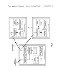 | 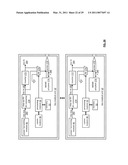 |
 |  |
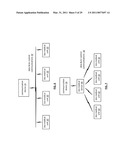 |  |
 | 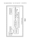 |
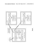 |  |
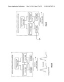 |  |
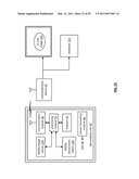 | 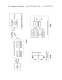 |
 | 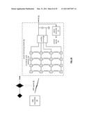 |
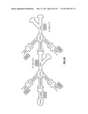 | 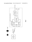 |
 |  |
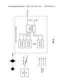 | 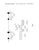 |
 |  |
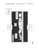 | 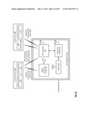 |
 | 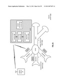 |
 |  |
| New patent applications from these inventors: | |
| Date | Title |
|---|---|
| 2016-05-19 | Rf bus controller |
| 2015-11-19 | Portable computing device with wireless power distribution |
| 2015-11-05 | Bio-medical unit and applications for cancer treatment |
| 2015-10-01 | Wireless bus for intra-chip and inter-chip communication, including wireless-enabled component (wec) embodiments |
| 2015-08-06 | Creating a system on the fly and applications thereof |
| Top Inventors for class "Surgery: light, thermal, and electrical application" | |
| Rank | Inventor's name |
|---|---|
| 1 | Imad Libbus |
| 2 | Jeffrey E. Stahmann |
| 3 | Robert J. Greenberg |
| 4 | Michael A. Moffitt |
| 5 | Andre B. Walker |