Patent application title: APPARATUS AND METHOD FOR RECYCLING MAGNESIUM ALLOY SCRAP
Inventors:
Yen Jun Chung (Seoul, KR)
Jae Kuen Lee (Gyeonggi-Do, KR)
Assignees:
Hyundai Motor Company
IPC8 Class: AB22D100FI
USPC Class:
164 661
Class name: Process shaping liquid metal against a forming surface applying an inert or reducing gaseous atmosphere to work
Publication date: 2010-09-23
Patent application number: 20100236745
Inventors list |
Agents list |
Assignees list |
List by place |
Classification tree browser |
Top 100 Inventors |
Top 100 Agents |
Top 100 Assignees |
Usenet FAQ Index |
Documents |
Other FAQs |
Patent application title: APPARATUS AND METHOD FOR RECYCLING MAGNESIUM ALLOY SCRAP
Inventors:
Yen Jun Chung
Jae Kuen Lee
Agents:
EDWARDS ANGELL PALMER & DODGE LLP
Assignees:
Origin: BOSTON, MA US
IPC8 Class: AB22D100FI
USPC Class:
Publication date: 09/23/2010
Patent application number: 20100236745
Abstract:
The present invention is directed, in general, to an apparatus for
recycling magnesium alloy scrap. In particular, an apparatus for
recycling magnesium alloy scrap includes a melting furnace formed with a
tapping part, having a first filter for removing impurities present in
molten scrap, and capable of being tilted toward the tapping part; a
first cleaning furnace disposed on a side of the melting furnace, having
a gas injecting part for injecting an inert gas in the molten metal and
capturing and removing impurities present in the molten metal, and
capable of being tilted; a second cleaning furnace disposed on a side of
the first cleaning furnace, and having a pump to tap a predetermined
amount of the molten metal supplied from the first cleaning furnace and a
second filter to remove impurities in pumped molten metal; and an ingot
forming furnace disposed on a side of the second cleaning furnace, and
configured to form an ingot using the predetermined molten metal supplied
from the second cleaning furnace.Claims:
1. An apparatus for recycling magnesium alloy scrap, comprising:a melting
furnace formed with a tapping part at a side of an upper end thereof,
having a first filter for removing impurities in molten scrap which was
melted in an inner space of the melting furnace, and capable of being
tilted toward the tapping part so that molten metal can be tapped through
the first filter;a first cleaning furnace disposed on a side of the
melting furnace, having a gas injecting part for injecting an inert gas
in the molten metal supplied from the melting furnace and thereby
capturing and removing impurities present in the molten metal, and
capable of being tilted so that the molten metal from which the
impurities have been removed can be tapped;a second cleaning furnace
disposed on a side of the first cleaning furnace, and having a pump which
is installed to tap a predetermined amount of the molten metal supplied
from the first cleaning furnace and a second filter which is installed on
a lower portion of the pump to remove impurities in pumped molten metal;
andan ingot forming furnace disposed on a side of the second cleaning
furnace, and configured to form an ingot using the predetermined molten
metal supplied from the second cleaning furnace.
2. The apparatus according to claim 1, wherein a closing section is installed on an upper end of each of the melting furnace and the cleaning furnaces to close the upper end.
3. The apparatus according to claim 2, wherein a hydraulic opening and closing device is installed on a distal end of the tapping part.
4. The apparatus according to claim 1, wherein the first filter comprises a metallic filter of 30 to 50 mesh, and the second filter comprises a metallic filter of 200 to 500 mesh.
5. The apparatus according to claim 1, wherein the gas injecting part comprises a valve for controlling supply of the inert gas, a connection pipe connected to the valve to allow the inert gas to flow therethrough, and a porous plate connected to an end of the connection pipe to inject the inert gas.
6. A method for recycling magnesium alloy scrap, comprising the steps of:melting magnesium alloy scrap;tapping molten scrap by passing it through a first filter, and thereby primarily filtering coarse impurities in molten metal;conducting a bubbling process by supplying an inert gas into the molten scrap having undergone primary filtering and thereby capturing and separating impurities present in the molten metal;conducting a precipitation process by maintaining the molten scrap having undergone the bubbling process and thereby precipitating and separating impurities present in the molten metal;regulating alloy compositions of the molten scrap having undergone the precipitation process; andpumping a predetermined amount of the molten metal into an ingot mold by passing it through a second filter part, and thereby conducting secondary filtering.
7. The method according to claim 6, wherein the inert gas is supplied in a rate of 0.8 to 1.0 L/min under pressure of 0.2 kg/cm.sup.2.
Description:
CROSS-REFERENCE TO RELATED APPLICATION
[0001]This application claims under 35 U.S.C. §119(a) the benefit of Korean Patent Application No. 10-2009-0024321, filed on Mar. 23, 2009, the entire contents of which are incorporated herein by reference.
BACKGROUND OF THE INVENTION
Field of the Invention
[0002]The present invention relates, generally, to an apparatus and a method for recycling magnesium alloy scrap and, more particularly, to an apparatus and a method for recycling magnesium alloy scrap, where the method can remove foreign substances and other impurities included in magnesium alloy scrap to suitably regenerate magnesium alloy.
[0003]In general, magnesium alloy has excellent specific strength and elastic modulus and is capable of absorbing vibrations, shocks and electromagnetic waves very well. Therefore, magnesium alloy is widely used to form parts for transportation machinery, for example, but not limited to, automobiles and airplanes.
[0004]In general, magnesium alloy products are mainly fabricated by gravity casting or die casting. In die casting, a substantial amount of scrap, including foreign substances and other impurities, is produced because of the characteristics of the die casting.
[0005]Recently, in order to reduce contamination of molten metal while melting and casting magnesium alloy, regeneration techniques which maintain an inert gas atmosphere or use synthetic flux have been used. However, when employing these regeneration techniques impurities such as Fe, Ni, Cu, Si, and so forth are not always perfectly removed.
[0006]The above information disclosed in this the Background section is only for enhancement of understanding of the background of the invention and therefore it may contain information that does not form the prior art that is already known in this country to a person of ordinary skill in the art.
SUMMARY OF THE INVENTION
[0007]Accordingly, the present provides an apparatus and a method for recycling magnesium alloy scrap which can effectively remove impurities included in magnesium alloy scrap.
[0008]In another preferred embodiment, the present invention provides an apparatus and a method for recycling magnesium alloy scrap which suitably allows a process for removing impurities included in magnesium alloy scrap to be automated.
[0009]In a preferred embodiment of the present invention, there is provided an apparatus for recycling magnesium alloy scrap, comprising a melting furnace that is suitably formed with a tapping part at a side of an upper end thereof, having a first filter for suitably removing impurities in molten scrap melted in an inner space of the melting furnace, and capable of being tilted toward the tapping part so that molten metal can be tapped through the first filter; a first cleaning furnace that is suitably disposed on a side of the melting furnace, having a gas injecting part for injecting an inert gas to the molten metal supplied from the melting furnace and thereby capturing and removing impurities present in the molten metal, and capable of being tilted so that the molten metal removed with the impurities can be tapped; a second cleaning furnace that is suitably disposed on a side of the first cleaning furnace, and having a pump which is installed to tap a predetermined amount of the molten metal supplied from the first cleaning furnace and a second filter which is installed on a lower portion of the pump to suitably remove impurities in pumped molten metal; and an ingot forming furnace disposed on a side of the second cleaning furnace, and suitably configured to form an ingot using the predetermined molten metal supplied from the second cleaning furnace.
[0010]In certain preferred embodiments, a closing section may be suitably installed on an upper end of each of the melting furnace and the cleaning furnaces to close the upper end.
[0011]Preferably, a hydraulic opening and closing device may be suitably installed on a distal end of the tapping part.
[0012]In certain exemplary embodiments, the first filter may comprise a metallic filter of 30 to 50 mesh, and the second filter may comprise a metallic filter of 200 to 500 mesh.
[0013]Preferably, the gas injecting part may comprise a valve for suitably controlling supply of the inert gas, a connection pipe suitably connected to the valve to flow the inert gas therethrough, and a porous plate suitably connected to an end of the connection pipe to inject the inert gas.
[0014]According to another preferred embodiment, the present invention features a method for recycling magnesium alloy scrap, comprising the steps of melting magnesium alloy scrap; tapping molten scrap by suitably passing it through a first filter, and thereby primarily filtering coarse impurities in molten metal; conducting a bubbling process by supplying an inert gas in the molten scrap having undergone primary filtering and thereby suitably capturing and separating impurities in the molten metal; conducting a suitable precipitation process by maintaining the molten scrap having undergone the bubbling process and thereby precipitating and separating impurities present in the molten metal; suitably regulating alloy compositions of the molten scrap having undergone the precipitation process; and suitably pumping a predetermined amount of the molten metal into an ingot mold by passing it through a second filter part, and thereby conducting secondary filtering.
[0015]Preferably, the inert gas may be supplied at a rate of 0.8 to 1.0 L/min under pressure of 0.2 kg/cm2.
[0016]It is understood that the term "vehicle" or "vehicular" or other similar term as used herein is inclusive of motor vehicles in general such as passenger automobiles including sports utility vehicles (SUV), buses, trucks, various commercial vehicles, watercraft including a variety of boats and ships, aircraft, and the like, and includes hybrid vehicles, electric vehicles, plug-in hybrid electric vehicles, hydrogen-powered vehicles and other alternative fuel vehicles (e.g. fuels derived from resources other than petroleum).
[0017]As referred to herein, a hybrid vehicle is a vehicle that has two or more sources of power, for example both gasoline-powered and electric-powered.
[0018]The above features and advantages of the present invention will be apparent from or are set forth in more detail in the accompanying drawings, which are incorporated in and form a part of this specification, and the following Detailed Description, which together serve to explain by way of example the principles of the present invention.
BRIEF DESCRIPTION OF THE DRAWINGS
[0019]The above and other objects, features and other advantages of the present invention will be more clearly understood from the following detailed description taken in conjunction with the accompanying drawings, in which:
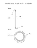
[0020]FIG. 1 is a schematic sectional view illustrating an apparatus for recycling magnesium alloy scrap according to preferred embodiments of the present invention;
[0021]FIG. 2 is a partial perspective view illustrating a melting furnace of the apparatus for recycling magnesium alloy scrap according to other preferred embodiments of the present invention;
[0022]FIG. 3 is a partial perspective view illustrating a tapping part of the melting furnace of the apparatus for recycling magnesium alloy scrap according to preferred embodiments of the present invention;
[0023]FIG. 4 is a schematic perspective view illustrating a gas injecting part installed in a first cleaning furnace of the apparatus for recycling magnesium alloy scrap according to certain preferred embodiments of the present invention;
[0024]FIG. 5 is a perspective view illustrating a porous plate of the gas injecting part installed in the first cleaning furnace of the apparatus for recycling magnesium alloy scrap according to preferred embodiments of the present invention;
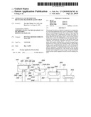
[0025]FIG. 6 is a perspective view illustrating pumping means and a second filter which are installed in a second cleaning furnace of the apparatus for recycling magnesium alloy scrap according to preferred embodiments of the present invention;
[0026]FIG. 7 is a perspective view illustrating a second filter installed in the pumping means of the apparatus for recycling magnesium alloy scrap according to preferred embodiments of the present invention;
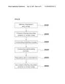
[0027]FIG. 8 is a flow chart explaining a method for recycling magnesium alloy scrap according to preferred embodiments of the present invention; and
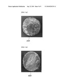
[0028]FIGS. 9 through 11 are views showing samples obtained by recycling magnesium alloy scrap.
DETAILED DESCRIPTION
[0029]As described herein, the present invention includes an apparatus for recycling magnesium alloy scrap, comprising a melting furnace formed with a tapping part at a side of an upper end thereof, a first cleaning furnace disposed on a side of the melting furnace, a second cleaning furnace disposed on a side of the first cleaning furnace, and an ingot forming furnace disposed on a side of the second cleaning furnace.
[0030]In one embodiment, the melting furnace further comprises a first filter for removing impurities in molten scrap that was melted in an inner space of the melting furnace, and capable of being tilted toward the tapping part so that molten metal can be tapped through the first filter.
[0031]In another embodiment, the first cleaning furnace further comprises a gas injecting part for injecting an inert gas in the molten metal supplied from the melting furnace and thereby capturing and removing impurities present in the molten metal, and capable of being tilted so that the molten metal from which the impurities have been removed can be tapped.
[0032]In another further embodiment, the second cleaning furnace further comprises a pump which is installed to tap a predetermined amount of the molten metal supplied from the first cleaning furnace and a second filter which is installed on a lower portion of the pump to remove impurities in pumped molten metal.
[0033]In one embodiment, the ingot forming furnace is configured to form an ingot using the predetermined molten metal supplied from the second cleaning furnace.
[0034]In another aspect, the invention features a method for recycling magnesium alloy scrap, comprising the steps of melting magnesium alloy scrap, tapping molten scrap by passing it through a first filter, conducting a bubbling process, conducting a precipitation process, regulating alloy compositions of the molten scrap having undergone the precipitation process; and pumping a predetermined amount of the molten metal into an ingot mold.
[0035]In one embodiment, passing molten scrap through a first filter results in primarily filtering coarse impurities in molten metal.
[0036]In another embodiment, the bubbling process consists of supplying an inert gas into the molten scrap having undergone primary filtering and thereby capturing and separating impurities present in the molten metal.
[0037]In another further embodiment, the precipitation process is carried out by maintaining the molten scrap having undergone the bubbling process and thereby precipitating and separating impurities present in the molten metal.
[0038]In one embodiment, the pumping step further comprises passing the molten metal through a second filter part, and thereby conducting secondary filtering.
[0039]Reference will now be made in greater detail to preferred embodiments of the invention, examples of which are illustrated in the accompanying drawings. Wherever possible, the same reference numerals will be used throughout the drawings and the description to refer to the same or like parts.
[0040]As described herein, FIG. 1 is a schematic sectional view illustrating an apparatus for recycling magnesium alloy scrap according to preferred embodiments of the present invention, as described herein, FIG. 2 is a partial perspective view illustrating a melting furnace of the apparatus for recycling magnesium alloy scrap according to preferred embodiments of the present invention, as described herein, FIG. 3 is a partial perspective view illustrating a tapping part of the melting furnace of the apparatus for recycling magnesium alloy scrap according to certain preferred embodiments of the present invention, as described herein, FIG. 4 is a schematic perspective view illustrating a gas injecting part installed in a first cleaning furnace of the apparatus for recycling magnesium alloy scrap according to other preferred embodiments of the present invention, as described herein, FIG. 5 is a perspective view illustrating a porous plate of the gas injecting part installed in the first cleaning furnace of the apparatus for recycling magnesium alloy scrap according to certain preferred embodiments of the present invention, as described herein, FIG. 6 is a perspective view illustrating pumping means and a second filter which are installed in a second cleaning furnace of the apparatus for recycling magnesium alloy scrap according to other preferred embodiments of the present invention, and as described herein, FIG. 7 is a perspective view illustrating a second filter installed in the pumping means of the apparatus for recycling magnesium alloy scrap according to certain preferred embodiments of the present invention.
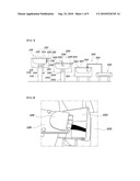
[0041]According to certain exemplary embodiments, and referring for example to FIG. 1, an apparatus for recycling magnesium alloy scrap in accordance with an embodiment of the present invention preferably includes a melting furnace 100 that is suitably configured to receive and melt magnesium alloy scrap and remove impurities present in molten scrap, a first cleaning furnace 200 that is suitably disposed on a side of the melting furnace 100 and that is suitably configured to inject an inert gas in molten metal suitably supplied from the melting furnace 100 and thereby remove impurities in the molten metal, a second cleaning furnace 300 that is suitably disposed on a side of the first cleaning furnace 200 and configured to perform secondary filtering for molten metal supplied from the first cleaning furnace 200 and tap a predetermined amount of filtered molten metal, and an ingot forming furnace 400 that is suitably disposed on a side of the second cleaning furnace 300 and configured to receive molten metal pumped from the second cleaning furnace 300 and form an ingot.
[0042]Preferably, the melting furnace 100 includes a pot 110, tilting means 140 for tilting the pot 110, a closing section 120 coupled to the upper end of the pot 110, and a first filter 130 that is suitably arranged in the pot 110 to remove impurities present in molten metal.
[0043]According to certain preferred embodiments, the pot 110 has a configuration of a cylinder which is suitably open at the upper end thereof, so that a predetermined space is suitably defined therein. Preferably, scrap is received in the predetermined space defined in the pot 110. According to certain preferred embodiments, the configuration of the pot 110 is not particularly limited and may suitably comprise a polygonal shape. According to further preferred embodiments, heating means 150 for melting magnesium alloy scrap received in the pot 110 are suitably arranged on a side surface of the pot 110. Preferably, a power source part 160 for supplying power to the heating means 150 can be suitably connected to the heating means 150.
[0044]According to certain exemplary embodiments, a tapping part 126 is suitably formed at a side of the upper end of the pot 110, and molten scrap melted in the pot 110 can be discharged through the tapping part 126. According to other certain exemplary embodiments, and referring to FIG. 2, an opening and closing device 128 for suitably controlling opening and closing of the tapping part 126 is suitably mounted to the distal end of the tapping part 126. Preferably, separate hydraulic means (not shown) may be suitably connected to the opening and closing device 128 so that the opening and closing device 128 can be actuated by the hydraulic means.
[0045]According to further exemplary embodiments, if scrap is received and a process starts, the opening and closing device 128 suitably closes the distal end of the tapping part 126. Accordingly, when molten metal having undergone the process flows to the tapping part 126, the opening and closing device 128 is suitably opened to provide a flow path of the molten metal.
[0046]According to other exemplary embodiments, and referring back to FIG. 1, in order to tap off the molten metal accommodated in the pot 110, the tilting means 140 for tilting the pot 110 is suitably arranged on the lower part of the pot 110. Preferably, the tilting means 140 is suitably composed of a support 142 which supports the pot 110 with respect to the ground and a rotation shaft 144 which is installed on the support 142 to tilt the pot 110. According to other preferred embodiments, driving means (not shown) for providing rotation driving force may be suitably connected to the rotation shaft 144.
[0047]According to further preferred embodiments, the tilting means 140 is suitably arranged to support both side surfaces of the pot 110. Due to this fact, the pot 110 can be tilted to be inclined toward the tapping part 126.
[0048]Preferably, the closing section 120 is suitably provided to the upper end of the pot 110 so as to prevent molten scrap heated and melted in the pot 110 from being oxidated due to exposure to the air for an extended period. In further preferred embodiments, the closing section 120 functions to suitably cover the upper end of the pot 110 and closes the inside of the pot 110.
[0049]In other preferred embodiments, the closing section 120 can have two closing parts 122 and 124. Preferably, these closing parts 122 and 124 are suitably structured such that each of them can be rotated upward and downward about a shaft element. Preferably, one closing part 122 can be used as an entrance for introducing scrap, and the other closing part 124 can be used as a cover for the tapping part 126.
[0050]According to other further embodiments of the present invention, the first filter 130 for removing impurities in molten metal is suitably arranged in the pot 110. According to certain exemplary embodiments, for example as shown in FIG. 3, the first filter 130 is suitably arranged adjacent to the tapping part 126 in the pot 110. Preferably, the first filter 130 comprises a rectangular plate-shaped filter of 30 to 50 mesh. In certain embodiments, it is preferred that the first filter 130 be suitably formed of a metallic material. Accordingly, the lifetime of the first filter 130 can be extended, and maintenance and repair can be easily performed.
[0051]In other certain embodiments, if the pot 110 is stilted to be suitably inclined toward the tapping part 126, the molten metal in the pot 110 flows through the first filter 130, and coarse impurities in the molten metal are filtered by the first filter 130.
[0052]According to certain exemplary embodiments, and referring back to FIG. 1, the first cleaning furnace 200 is suitably disposed on the side of the melting furnace 100. Preferably, the first cleaning furnace 200 functions to additionally remove impurities from the primarily filtered molten metal. According to further preferred embodiments, a cover 220 for closing the upper end of a first cleaning furnace pot 210 is provided to the upper end of the first cleaning furnace 200. Preferably, a guide member 222 can be provided to the cover 220 to guide introduction of the molten metal tapped off from the melting furnace 100 into the first cleaning furnace 200.
[0053]According to other preferred embodiments, a first cleaning furnace tapping part 226 is suitably formed at a side of the upper end of the first cleaning furnace pot 210. Preferably, first cleaning furnace tilting means 240 for tilting the first cleaning furnace pot 210 are suitably arranged on the lower part of the first cleaning furnace pot 210. Since the first cleaning furnace tapping part 226 and the first cleaning furnace tilting means 240 are suitably constructed in the same manner as the tapping part 126 and the tilting means 140 of the melting furnace 110, detailed description thereof will be omitted herein.
[0054]According to other certain exemplary embodiments, a gas injecting part 230 for supplying an inert gas in molten scrap accommodated in the first cleaning furnace pot 210 is suitably installed in the first cleaning furnace pot 210. Preferably, the gas injecting part 230 is suitably installed to pass through the center portion of the cover 220 in the vertical direction. Preferably, the upper end of the gas injecting part 230 may be suitably connected with an inert gas source (not shown).
[0055]According to certain exemplary embodiments, and referring to FIGS. 4 and 5, the gas injecting part 230 preferably comprises a connection pipe 232 for flowing an inert gas, a valve 234 installed on the upper end of the connection pipe 232 to control the supply of the inert gas, and a porous injection plate 236 suitably installed on the lower end of the connection pipe 232 to inject the inert gas flowing through the connection pipe 232. Preferably, the injection plate 236 has a circular plate-like shape and is suitably defined with a plurality of injection holes 238 on the upper and lower surfaces thereof.
[0056]According to certain preferred embodiments, if the inert gas is suitably injected from the gas injecting part 230 in molten metal accommodated in the first cleaning furnace pot 210, fine impurities in the molten metal are captured by the inert gas and are widely dispersed. Accordingly, the fine impurities spread in this way float up to the top of the molten metal. In further related embodiments, the impurities floated in the molten metal can be removed by separate impurity removing means (not shown) or a worker.
[0057]Accordingly, in further preferred embodiments, with the fine impurities suitably captured by the inert gas and widely dispersed, by conducting a precipitation process for a predetermined time and then removing the impurities, the effect of removing impurities can be maximized.
[0058]Preferably, when the fine impurities in the molten scrap are suitably removed, the first cleaning furnace 210 is tilted, and due to this fact, the molten scrap with the fine impurities removed therefrom is suitably discharged through the first cleaning furnace tapping part 226.
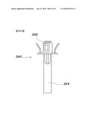
[0059]According to certain exemplary embodiments, and referring back to FIG. 1, the second cleaning furnace 300 is suitably disposed on the side of the first cleaning furnace 200, and the inside of the second cleaning furnace 300 is then suitably closed by closing means 320. Preferably, a guide member 322 is provided to the closing means 320 to suitably guide the introduction of the molten metal tapped off from the first cleaning furnace tapping part 226 into the second cleaning furnace 300.
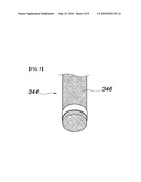
[0060]Preferably, pumping means 340 is installed in the second cleaning furnace 300 to tap a predetermined amount of molten metal supplied from the first cleaning furnace 200. According to certain exemplary embodiments, and referring to FIGS. 6 and 7 for example, the pumping means 340 is composed of a pump 342 for tapping the predetermined amount of molten metal and a second filter 344 which is suitably installed on the lower end of the pump 342 to remove coarse impurities remaining in the molten metal which has been pumped and tapped. Preferably, the second filter 342 comprises a metallic filter which is of 200 to 500 mesh and possesses a plurality of pores 346.
[0061]Accordingly, in further preferred embodiments, the predetermined amount of molten metal can be tapped from the second cleaning furnace 300 so that a size of an ingot can be determined depending upon the operating time of the pump 342. Preferably, as the molten metal tapped from the second cleaning furnace 300 passes through the second filter 344 installed on the lower portion of the pump 342, the coarse impurities in the molten metal can be filtered again.
[0062]In further preferred embodiments, the molten metal filtered through the second filter 344 in this way is pumped and supplied to the ingot forming furnace 400. The ingot forming furnace 400 can form an ingot having a predefined size using the supplied molten metal.
[0063]As described herein, in the apparatus for recycling magnesium alloy scrap according to the present invention, various cleaning processes for recycling magnesium alloy scrap can be continuously conducted.
[0064]Hereafter, a method for recycling magnesium alloy scrap in accordance with another preferred embodiment of the present invention is described with reference to FIGS. 8 through 11.
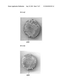
[0065]FIG. 8 is a flow chart explaining a method for recycling magnesium alloy scrap according to preferred exemplary embodiments of the present invention, and FIGS. 9 through 11 are exemplary views showing samples obtained by recycling magnesium alloy scrap.
[0066]According to certain exemplary embodiments, and referring to FIG. 8, the method for recycling magnesium alloy scrap according to the present invention preferably comprises the steps of suitably melting magnesium alloy scrap (S100), primarily filtering coarse impurities in molten scrap (S200), suitably conducting bubbling and participating processes to remove fine impurities (S300, S400), suitably regulating alloy compositions (S500), and secondarily filtering coarse impurities in molten metal (S600).
[0067]In a further preferred embodiments, first, after magnesium alloy scrap is suitably received in a melting furnace, the scrap is heated to about 650° C. by heating means (S100). Then, molten scrap is passed through a first filter of 40 mesh by tilting the melting furnace so that coarse impurities in the molten scrap are suitably removed, whereby first filtering is implemented (S200).
[0068]According to other exemplary embodiments, and referring to FIG. 9(9a, 9b), by evaluating corrosion resistance of a sample (500) not having undergone filtering and a sample (600) having undergone filtering, it was found that the corrosion resistance of the sample (600) having undergone filtering is excellent.
[0069]According to further exemplary embodiments, the molten scrap having undergone first filtering is moved to a first cleaning furnace, an inert gas, for example, but not limited to, an argon gas, is suitably injected from a gas injecting part in molten metal, and a bubbling process is suitably conducted to capture fine impurities in the molten metal (S300). Here, in further exemplary embodiments, the argon gas is supplied in a rate of 0.8 to 1.0 L/min under pressure of 0.2 kg/cm2.
[0070]Preferably, after the bubbling process is finished, a precipitation process is suitably conducted to maintain the molten scrap for a preselected time and thereby precipitate impurities (S400).
[0071]According to certain exemplary embodiments, and referring to FIGS. 10(10a, 10b) and 11(11a, 11b), in order to suitably observe the effects of the bubbling process and precipitation process, the corrosion resistance of a sample (500) not having undergone the bubbling process and the precipitation process and the corrosion resistance of a sample (600) having undergone the bubbling process for about 20 minutes and the precipitation process for about an hour were evaluated. As a result of the evaluation, it was found that the sample (600) having undergone the bubbling process and the precipitation process has excellent corrosion resistance.
[0072]In further preferred embodiments, the constituents of the molten metal having completely undergone the precipitation process are suitably analyzed and the compositions of necessary alloy constituents are suitably regulated so as to conduct an alloying process (S500).
[0073]Preferably, the molten metal having completely undergone the alloying process flows to a second cleaning furnace. In a further related embodiment, the molten metal stored in the second cleaning furnace is pumped to supply a predetermined amount of molten metal in an ingot mold and is passed through a second filter of 320 mesh so as to conduct secondary filtering (S600), whereby the method for recycling magnesium alloy scrap is completed.
[0074]As described herein, in the method for recycling magnesium alloy scrap according to the present invention, as the filtering, bubbling, precipitating and alloying processes are continuously conducted, cleaning effects can be suitably maximized.
[0075]As is apparent from the above description, the present invention provides advantages in that, because of the filtering, bubbling and precipitating processes which are conducted to regenerate magnesium alloy scrap, the impurities included in the magnesium alloy scrap can be effectively removed.
[0076]Also, as described herein, by automating the filtering, bubbling and precipitating processes to regenerate magnesium alloy scrap, processes for recycling magnesium alloy scrap can be continuously conducted.
[0077]Further, as described herein, since a filter for filtering magnesium alloy scrap comprises a metallic filter, the lifetime of the filter can be extended, and maintenance and repair can be easily performed.
[0078]Further, as described herein, by conducting the processes for recycling magnesium alloy scrap in a closed space, oxidation of molten metal can be maximally suppressed.
[0079]Although preferred embodiments of the present invention have been described for illustrative purposes, those skilled in the art will appreciate that various modifications, additions and substitutions are possible, without departing from the scope and spirit of the invention as disclosed in the accompanying claims.
User Contributions:
comments("1"); ?> comment_form("1"); ?>Inventors list |
Agents list |
Assignees list |
List by place |
Classification tree browser |
Top 100 Inventors |
Top 100 Agents |
Top 100 Assignees |
Usenet FAQ Index |
Documents |
Other FAQs |
User Contributions:
Comment about this patent or add new information about this topic:
| People who visited this patent also read: | |
| Patent application number | Title |
|---|---|
| 20100240409 | WIRELESS COMMUNICATION SYSTEM, WIRELESS BASE STATION, WIRELESS TERMINAL STATION, AND TRANSMISSION POWER CONTROL METHOD USING THE SAME |
| 20100240408 | METHOD AND DEVICE FOR CONTROLLING FLOOR IN PUSH TO SERVICE |
| 20100240407 | Method and System for Managing Channel Set for Dynamic Channel Allocation |
| 20100240406 | Method and Apparatus for Carrier Management |
| 20100240405 | DEVICE AND METHOD FOR PROVIDING AND DISPLAYING ANIMATED SMS MESSAGES |
Images included with this patent application:
 |  |
 |  |
 |  |
 |  |
 |  |
| Similar patent applications: | |
| Date | Title |
|---|---|
| 2008-10-09 | Method and apparatus for producing thin magnesium based alloy plate |
| 2009-03-12 | Technique for forming titanium alloy tubes |
| 2010-04-08 | Method for preventing formation of cellular gamma prime in cast nickel superalloys |
| 2011-01-20 | Method and apparatus for making magnesium-based alloy |
| 2011-09-08 | Environment-friendly manganese brass alloy and manufacturing method thereof |
| New patent applications in this class: | |
| Date | Title |
|---|---|
| 2016-05-12 | Process and apparatus for casting titanium aluminide components |
| 2013-08-15 | Forming metal preforms and metal balls |
| 2013-02-07 | Pour ladle for molten metal |
| 2011-08-04 | Utilization of carbon dioxide and/or carbon monoxide gases in processing metallic glass compositions |
| 2010-08-26 | Casting process for aluminum alloys |
| New patent applications from these inventors: | |
| Date | Title |
|---|---|
| 2015-07-02 | Process for preparing rare earth magnets |
| 2010-02-25 | Magnesium oil pan |
| Top Inventors for class "Metal founding" | |
| Rank | Inventor's name |
|---|---|
| 1 | Theodore A. Waniuk |
| 2 | Steven J. Bullied |
| 3 | Joseph C. Poole |
| 4 | Carl R. Verner |
| 5 | Christopher D. Prest |