Patent application title: CLOSURE DEVICES, SYSTEMS, AND METHODS
Inventors:
Laveille K. Voss (Belmont, CA, US)
Aaron M. Fortson (Fremont, CA, US)
Aaron M. Fortson (Fremont, CA, US)
Assignees:
ABBOTT VASCULAR INC.
IPC8 Class: AA61B1704FI
USPC Class:
606144
Class name: Instruments suture, ligature, elastic band or clip applier mechanical suture or ligature applier
Publication date: 2010-07-15
Patent application number: 20100179572
Inventors list |
Agents list |
Assignees list |
List by place |
Classification tree browser |
Top 100 Inventors |
Top 100 Agents |
Top 100 Assignees |
Usenet FAQ Index |
Documents |
Other FAQs |
Patent application title: CLOSURE DEVICES, SYSTEMS, AND METHODS
Inventors:
Laveille K. Voss
Aaron M. Fortson
Agents:
WORKMAN NYDEGGER
Assignees:
ABBOTT VASCULAR INC.
Origin: SALT LAKE CITY, UT US
IPC8 Class: AA61B1704FI
USPC Class:
606144
Publication date: 07/15/2010
Patent application number: 20100179572
Abstract:
A closure system is provided that may include a plurality of needle
carriers each having a distal end and a proximal end and a plurality of
detachable needles in which at least one of the detachable needles is
detachably coupled to the distal end of one of the needle carriers. The
detachable needle may be configured to resist proximal movement when
deployed in a vessel wall. The closure system may further include at
least one suture secured to each of the detachable needles and a guide
member having a plurality of first lumens defined therein that extend
distally from a proximal end of the guide member toward a distal end of
the guide member in which each of the first lumens is sized to receive
one of the needle carriers and one of the detachable needles coupled to
the needle carrier. The first lumens may be further configured to direct
the needle carrier and the detachable needle radially outward and
distally away from the guide member.Claims:
1. A closure system, comprising:a plurality of needle carriers each having
a distal end and a proximal end;a plurality of detachable needles,
wherein at least one of the detachable needles is detachably coupled to
the distal end of one of the needle carriers, the detachable needle being
configured to resist proximal movement when deployed in a vessel wall;at
least one suture secured to each of the detachable needles;a guide member
having a plurality of first lumens defined therein extending distally
from a proximal end of the guide member toward a distal end of the guide
member, wherein each of the first lumens is sized to receive one of the
needle carriers and one of the detachable needles coupled to the needle
carrier, the first lumens being further configured to direct the needle
carrier and the detachable needle radially outward and distally away from
the guide member;an outer housing having a distal end and a proximal end,
wherein a second lumen is defined between the distal end of the outer
housing and the proximal end of the outer housing, the second lumen being
configured to receive at least a portion of the guide member; andan
anchor member configured to be at least partially disposed within the
second lumen, the anchor member comprising an anchor portion and an
elongate portion, the anchor portion being disposed in the inner lumen in
an initial configuration and configured to move to an expanded
configuration once when positioned distally from the distal end of the
outer housing.
2. The closure system of claim 1, further comprising an expandable plug configured to be positioned between the guide member and the anchor member.
3. The closure system of claim 2, wherein the expandable plug is coupled to the distal end of the guide member.
4. The closure system of claim 1, wherein the first lumens each include an axial portion and a curved, angled portion.
5. The closure system of claim 1, wherein the needle carriers comprise a suture receiving lumen configured to receive the suture associated with each of the detachable needles.
6. The closure system of claim 1, wherein at least one of the detachable needles includes a conical portion and a shaft, the conical portion having a tip and a base, the base being wider than the shaft.
7. The closure system of claim 1, wherein at least at least one of the detachable needles is configured to rotate in response to tension applied to at least one of the sutures.
8. The closure system of claim 7, wherein at least one of the sutures is secured to at least one of the detachable needles at a position that is radially offset from a central axis of the detachable needle.
9. The closure system of claim 7, wherein at least one of the sutures is secured to at least one of the detachable needles at a position that is distally offset from a proximal end of the detachable needle.
10. The closure system of claim 1, wherein the outer housing is coupled to a handle, the guide member is coupled to a first plunger, and the needle carriers are coupled to a second plunger.
11. The closure system of claim 10, wherein the guide member is moved between a retracted position in which the distal end of the guide member is positioned within the distal end of the outer housing and an extended position in which the distal end of the guide member is positioned distally of the distal end of the outer housing by moving the first plunger relative to the handle.
12. The closure system of claim 11, wherein the needle carriers are moved between a retracted position in which the detachable needles are positioned within the distal end of the guide member and an extended position in which the detachable needles are positioned distally of the distal end of the outer housing by moving the second plunger relative to the first handle.
13. The closure system of claim 12, wherein the second plunger is operable independently from the first plunger.
14. The closure system of claim 1, wherein the anchor member further includes a plurality of control members coupled thereto, the control members extending proximally through the guide member.
15. The closure system of claim 1, wherein at least one of the detachable needles is coupled to at least one of the needle carriers so as to provide a slip fit between at least one of the detachable needles and at least one of the needle carriers.
16. A closure system, comprising:a plurality of needle carriers having a distal end and a proximal end;a plurality of detachable needles, wherein at least one of the detachable needles is detachably coupled to the distal end of each of the needle carriers with a slip fit to allow the detachable carriers and the detachable needles to move together when moving in a distal direction to allow the detachable needles to detach from the needle carriers when the needle carriers are drawn in a proximal direction;at least one suture secured to each of the detachable needles;a guide member having a plurality of first lumens defined therein extending distally from a proximal end of the guide member toward a distal end of the guide member, wherein each of the first lumens is sized to receive one of the needle carriers and one of the detachable needles coupled to the needle carriers, the first lumens being further configured to direct the needle carrier and the detachable needle radially outward and distally away from the guide member;an outer housing having a distal end and a proximal end, wherein a second lumen is defined between the distal end of the outer housing and the proximal end of the outer housing, the second lumen being configured to receive at least a portion of the guide member; andan anchor member configured to be at least partially disposed within the second lumen, the anchor member comprising an anchor portion being disposed in the inner lumen in an initial configuration and configured to move to an expanded configuration once when positioned distally from the distal end of the outer housing.
17. The closure system of claim 16, further comprising an expandable plug configured to be positioned between the guide member and the anchor member.
18. The closure system of claim 17, wherein the expandable plug is coupled to the distal end of the guide member.
19. The closure system of claim 16, wherein at least one of the detachable needles includes a conical portion and a shaft, the conical portion having a tip and a base, the base being wider than the shaft.
20. The closure system of claim 16, wherein at least at least one of the detachable needles is configured to rotate in response to tension applied to at least one of the sutures.
21. A method of closing a puncture in a vessel, comprising:advancing a distal end of a first member into proximity with a puncture in a vessel wall, the first member having a first lumen defined therein;advancing an anchor member through the first lumen and distally from the distal end of the first member and expanding the anchor member distally of the puncture in the vessel.drawing the anchor member proximally into engagement with a posterior side of the vessel wall;advancing a guide member through the first lumen and distally from the distal end of the first member to expose openings in the guide member, each of the openings being in communication with one of a plurality of needle carrier lumens defined in the guide member,advancing needle carriers and needles coupled to the needle carriers through the needle carrier lumens to move the needles radially outward and distally away from a distal end of the guide member to pass the needles at least partially through the vessel wall, wherein sutures are further coupled to the needles;retracting the needle carriers into the guide member to detach the needles from the needle carriers;retracting the guide member into the first lumen; andestablishing tension in the sutures with a constrictor to move the needles toward each other to thereby close the puncture.
22. The method of claim 21, further comprising advancing an expandable plug through the first lumen and into contact with the vessel wall before advancing the needles carriers and needles coupled to the needle carriers through the needle carrier lumens.
23. The method claim 21, wherein advancing the needle carriers and the needles coupled to the needle carriers through the needle carrier lumens to move the needles radially outward and distally away from a distal end of the guide member includes using two needle carriers and two needles.
24. The method claim 21, wherein advancing the needle carriers and the needles coupled to the needle carriers through the needle carrier lumens to move the needles radially outward and distally away from a distal end of the guide member includes using four needle carriers and four needles.
Description:
CROSS-REFERENCE TO RELATED APPLICATIONS
[0001]This patent application claims the benefit of and priority to U.S. Provisional Patent Application Ser. No. 61/143,751, entitled "Vessel Closure Devices and Methods," filed Jan. 9, 2009, the disclosure of which is incorporated herein by reference in its entirety.
BACKGROUND
[0002]1. Technical Field
[0003]The present disclosure relates generally to medical devices and their methods of use. In particular, the present disclosure relates to vessel closure systems and devices and corresponding methods of use.
[0004]2. The Technology
[0005]Catheterization and interventional procedures, such as angioplasty or stenting, generally are performed by inserting a hollow needle through a patient's skin and tissue into the vascular system. A guidewire may be advanced through the needle and into the patient's blood vessel accessed by the needle. The needle is then removed, enabling an introducer sheath to be advanced over the guidewire into the vessel, e.g., in conjunction with or subsequent to a dilator.
[0006]A catheter or other device may then be advanced through a lumen of the introducer sheath and over the guidewire into a position for performing a medical procedure. Thus, the introducer sheath may facilitate introducing various devices into the vessel, while minimizing trauma to the vessel wall and/or minimizing blood loss during a procedure.
[0007]Upon completing the procedure, the devices and introducer sheath are removed, leaving a puncture site in the vessel wall. Traditionally, external pressure would be applied to the puncture site until clotting and wound sealing occur; however, the patient must remain bedridden for a substantial period after clotting to ensure closure of the wound. This procedure may also be time consuming and expensive, requiring as much as an hour of a physician's or nurse's time. It is also uncomfortable for the patient and requires that the patient remain immobilized in the operating room, catheter lab, or holding area. In addition, a risk of hematoma exists from bleeding before hemostasis occurs. Although some closure systems may be available, they provide limited control to flexibility to the operator, which may lead to improper or undesirable closure of the puncture site.
BRIEF SUMMARY
[0008]A closure system is provided that may include a plurality of needle carriers each having a distal end and a proximal end and a plurality of detachable needles in which at least one of the detachable needles is detachably coupled to the distal end of one of the needle carriers. The detachable needle may be configured to resist proximal movement when deployed in a vessel wall. The closure system may further include at least one suture secured to each of the detachable needles and a guide member having a plurality of first lumens defined therein that extend distally from a proximal end of the guide member toward a distal end of the guide member in which each of the first lumens is sized to receive one of the needle carriers and one of the detachable needles coupled to the needle carrier. The first lumens may be further configured to direct the needle carrier and the detachable needle radially outward and distally away from the guide member. An outer housing may have a distal end and a proximal end in which a second lumen is defined between the distal end of the outer housing and the proximal end of the outer housing. The second lumen may be configured to receive at least a portion of the guide member. An anchor member may be configured to be at least partially disposed within the second lumen. The anchor member may comprise an anchor portion and an elongate portion disposed in the inner lumen in an initial configuration and configured to move to an expanded configuration once when positioned distally from the distal end of the outer housing.
[0009]A closure system may include a plurality of needle carriers having a distal end and a proximal end. A plurality of detachable needles in which at least one of the detachable needles is detachably coupled to the distal end of each of the needle carriers with a slip fit to allow the detachable carriers and the detachable needles to move together when moving in a distal direction to allow the detachable needles to detach from the needle carriers when the needle carriers are drawn in a proximal direction. At least one suture may be secured to each of the detachable needles. A guide member has a plurality of first lumens defined therein extending distally from a proximal end of the guide member toward a distal end of the guide member in which each of the first lumens is sized to receive one of the needle carriers and one of the detachable needles coupled to the needle carriers the first lumens being further configured to direct the needle carrier and the detachable needle radially outward and distally away from the guide member. An outer housing may have a distal end and a proximal end, wherein a second lumen is defined between the distal end of the outer housing and the proximal end of the outer housing, the second lumen being configured to receive at least a portion of the guide member. An anchor member may be configured to be at least partially disposed within the second lumen. The anchor member may include an anchor portion disposed in the inner lumen in an initial configuration and configured to move to an expanded configuration once when positioned distally from the distal end of the outer housing.
[0010]A method of closing a puncture in a vessel includes advancing a distal end of a first member into proximity with a puncture in a vessel wall, the first member having a first lumen defined therein. An anchor member may then be advanced through the first lumen and distally from the distal end of the first member and expanding the anchor member distally of the puncture in the vessel. The anchor member may then be drawn proximally into engagement with a posterior side of the vessel wall. A guide member may then be advanced through the first lumen and distally from the distal end of the first member to expose openings in the guide member, each of the openings being in communication with one of a plurality of needle carrier lumens defined in the guide member. Needle carriers and needles coupled to the needle carriers may then be advanced through the needle carrier lumens to move the needles radially outward and distally away from a distal end of the guide member to pass the needles at least partially through the vessel wall, wherein sutures are further coupled to the needles. Thereafter, the needle carriers may be retracted into the guide member to detach the needles from the needle carriers and the guide member may be retracted into the first lumen. Tension may then be established in the sutures with a constrictor to move the needles toward each other to thereby close the puncture.
[0011]These and other advantages and features of the present disclosure will become more fully apparent from the following description and appended claims, or may be learned by the practice of the disclosure as set forth hereinafter.
BRIEF DESCRIPTION OF THE DRAWINGS
[0012]To further clarify at least some of the advantages and features of the present disclosure, a more particular description of the disclosure will be rendered by reference to specific embodiments thereof which are illustrated in the appended drawings. It is appreciated that these drawings depict only illustrated embodiments of the disclosure and are therefore not to be considered limiting of its scope. The disclosure will be described and explained with additional specificity and detail through the use of the accompanying drawings in which:
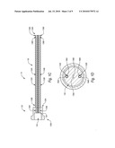
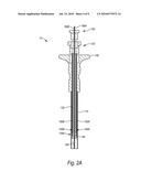
[0013]FIG. 1A illustrates a side view of a closure system according to one example;
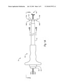
[0014]FIG. 1B illustrates an exploded view of the closure system of FIG. 1A;
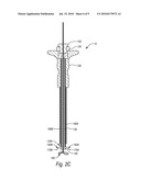
[0015]FIG. 1C illustrates a cross sectional view of the guide member and associated first plunger of FIG. 1B taken along section 1C-1C of FIG. 1B;
[0016]FIG. 1D illustrates a cross sectional view of the closure system shown in FIG. 1A taken along section 1D-1D of FIG. 1A;
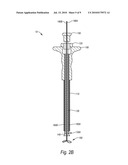
[0017]FIG. 2A illustrates a closure system in an a pre-deployed state according to one example;
[0018]FIG. 2B illustrates the closure system of FIG. 2A in an intermediate state according to one example;
[0019]FIG. 2C illustrates the closure system of FIGS. 2A-2B in a deployed state;
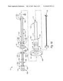
[0020]FIG. 3A illustrates steps for closing a puncture in a vessel wall in which a closure system is in an a pre-deployed state and in proximity to an arteriotomy according to one example;
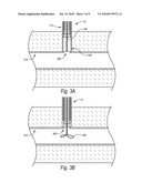
[0021]FIG. 3B illustrates steps for closing a puncture in a vessel wall in which the closure system of FIG. 3A is located relative to a vessel wall;
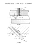
[0022]FIG. 3C illustrates steps for closing a puncture in a vessel wall in which detachable needles are deployed through the vessel wall;
[0023]FIG. 3D illustrates a more detailed view of engagement between a detachable needle and the vessel wall of FIG. 3A;
[0024]FIG. 3E illustrates steps for closing a puncture in a vessel wall in which the sutures and needles are secured in place to close the puncture in the vessel wall; and
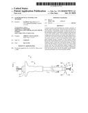
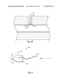
[0025]FIG. 4 illustrates a detachable needle according to one example.
[0026]It should be noted that the figures are not drawn to scale and that elements of similar structures or functions are generally represented by like reference numerals for illustrative purposes throughout the figures. It also should be noted that the figures are only intended to facilitate the description of example configurations of the present disclosure.
DETAILED DESCRIPTION
[0027]The present disclosure relates to devices, systems, and methods for closing an opening in a body lumen. In one example embodiment, a closure system of the present disclosure may allow an operator to quickly and efficiently close a body lumen opening while simultaneously providing the operator with a greater measure of control and flexibility in positioning and anchoring the closure system than previously available. For example, the closure system may allow an operator to achieve a more intimate securement of a closure element in the tissue surrounding a body lumen opening. In a yet further embodiment, the closure system may be compatible with a wider range of body lumen wall thicknesses, thereby taking into account the possibility of calcifications or scar tissue in the lumen wall.
[0028]FIG. 1A illustrates a side view of a closure system 10 according to one example. The closure system 10 may include a handle 100, an outer housing 110, a first plunger 120 coupled to a guide member 130, an optional plug 140, a second plunger 150 coupled to a plurality of needle carriers 160A, 160B, a plurality of detachable needles 170A, 170B removably coupled to the needle carriers 160A, 160B respectively, an anchor member 180 and control members 190A, 190B coupled to the anchor member 180.
[0029]The anchor member 180 and control members 190A, 190B may cooperate to allow the closure system 10 to be located relative to a puncture in a vessel wall, such as an arteriotomy. Any type of locator having any configuration may be used as desired to position the closure system 10 in proximity to a vessel wall.
[0030]In the illustrated example, the control members 190A, 190B can be manipulated to move the anchor member 180 between a pre-deployed state (not shown in FIG. 1A) to the expanded or deployed state shown in FIG. 1A. In particular, the control members 190A, 190B may be coupled to the anchor member 180 and extend proximally from the anchor member 180 through the plug 140, the guide member 130, the first plunger 120, and the second plunger 150. In the illustrated example, manipulation of the control members 190A, 190B may be performed manually, though it will be appreciated that any suitable device and/or method may be used to manipulate the control members 190A, 190B.
[0031]As shown in FIG. 1B, the control members 190A, 190B and the anchor member 180 may form a continuous member. In such an example, retracting the control members 190A, 190B may anchor the anchor member 180 against the distal surface of a vessel wall or any other surface against which the anchor member 180 is positioned. In one embodiment, retracting both control members 190A, 190B simultaneously may produce tension or some other force in the anchor member 180 which may increase the resistance of the anchor member 180 to contracting.
[0032]For example, the tension of both control members 190A, 190B may be simultaneously transferred to the anchor member 180 thereby creating sufficient tension in the anchor member 180 to resist movement away from its expanded configuration. In addition, providing an opposing force against a proximal surface of the anchor member 180, such as with a vessel wall, may also assist in creating sufficient tension in the anchor member 180 to resist contraction of the anchor member 180. In a further implementation, the wires of the anchor member 180 may overlap or cross over each other in order to increase resistance.
[0033]In at least one example, retracting only one of the control members 190A, 190B, may lessen the tension in the anchor member 180, thereby allowing the anchor member 180 to move from its deployed, expanded configuration to a contracted configuration. As a result, by retracting only one of the control members 190A or 190B, without applying tension to the other control member 190B or 190A or by applying a distal force to the other control member 190B or 190A, the anchor member 180 may contract and be retracted into the outer housing 110.
[0034]Referring again to FIG. 1A, the guide member 130 may be configured to house at least a portion of the control members 190A, 190B and to allow axial translation of the control members 190A, 190B relative to the guide member 130. Such a configuration may allow the control members 190A, 190B to be manipulated at a proximal location to control the anchor member 180 at a distal location.
[0035]The guide member 130, and thus the control members 190A, 190B that extend there through, may be at least partially housed within the outer housing 110 and/or within the handle 100. As previously discussed, the guide member 130 may be coupled to the first plunger 120. Such a configuration may cause actuation of the first plunger 120 to result in axial movement of the guide member 130. In at least one example, axial movement of the first plunger 120 results in similar axial movement of the guide member 130. Such a configuration may allow the first plunger 120 to extend and retract the guide member 130 from the outer housing 110 as desired. While actuation of the first plunger 120 may been described with reference to axial movement of the first plunger 120 relative to the handle 100, it will be appreciated that actuation of the first plunger 120 may include any type of action that results in desired movement of the guide member 130.
[0036]The optional plug 140 may be secured to the guide member 130 in such a manner that axial movement of the first plunger 120 also results in a corresponding movement of the plug 140. Such a configuration may thereby allow axial movement of the first plunger 120 to also extend and retract the plug 140 from the outer housing 110 as desired by extending and retracting the guide member 130. Although the guide member 130 and the plug 140 are shown as moving together, it will be appreciated that the plug 140 may also be independently controlled and moved, such as by the use of additional plungers and/or shafts.
[0037]In addition to serving as a mandrel to thereby move the plug, the guide member 130 may also be configured to house the needle carriers 160A, 160B and the detachable needles 170A, 170B. More specifically, the guide member 130 may be configured to allow the needle carriers 160A, 160B and the detachable needles 170A, 170B to move between a pre-deployed state and the deployed state shown in FIG. 1A. In a pre-deployed state (not shown in FIG. 1A), the needle carriers 160A, 160B and/or the detachable needles 170A, 170B are retracted within the guide member 130. In the deployed state shown in FIG. 1A, the detachable needles 170A, 170B and/or the needle carriers 160A, 160B extend radially and/or distally from the guide member 130.
[0038]The needle carriers 160A, 160B are coupled to the second plunger 150 in such a way that actuation of the second plunger 150 causes the needle carriers 160A, 160B to move between the pre-deployed and deployed states described above. In at least one example, axial movement of the second plunger 150 relative to the first plunger 120 moves the needle carriers 160A, 160B between the pre-deployed and deployed states. While actuation of the second plunger 150 may be provided by axial movement of the second plunger 150 relative to the first plunger 120, it will be appreciated that actuation of the second plunger 150 may include any type of action that results in desired movement of the needle carriers 160A, 160B.
[0039]As will be described in more detail, the actions described above allow the closure system 10 to deploy the detachable needles 170A, 170B into a vessel wall as part of a method for closing a puncture in the vessel wall. Exemplary structure of each of the components introduced above will first be introduced briefly followed by a discussion of the assembly and interaction of adjacent components. Thereafter, function of an exemplary closure system will be discussed, followed by a discussion of an exemplary method of closing a puncture in a vessel wall.
[0040]FIG. 1B illustrates an exploded view of the closure system 10. As illustrated in FIG. 1B, the handle 100 includes a distal end 100A and a proximal end 100B. A guide member receiving lumen 102 extends proximally from the distal end 100A. A first plunger receiving lumen 104 extends distally from the proximal end 100B and is in communication with the guide member receiving lumen 102. In the illustrated example, a shoulder 106 is formed at a transition between the guide member receiving lumen 102 and the first plunger receiving lumen 104.
[0041]The outer housing 110 may be coupled to the distal end 100A of the handle 100. In particular, the outer housing 110 may include a distal end 110A and a proximal end 110B. A guide member receiving lumen 112 may be formed therein that extends through the distal end 100A and the proximal end 110B. The guide member receiving lumen 112 may be configured to allow the guide member 130 to translate axially within the outer housing 110 as will be described in more detail hereinafter. In at least one example, the guide member receiving lumen 112 may have approximately the same size as the guide member receiving lumen 102 defined in the handle 102.
[0042]As shown in FIG. 1B, the proximal end 110B of the outer housing 110A may be coupled to the distal end 100A of the handle 100 in such a manner that the guide member receiving lumens 102, 112 are aligned to thereby form a single lumen that is in communication with the distal end 110A of the outer housing 110 and the first plunger receiving lumen 104 in the handle 100. Such a configuration may allow the first plunger 120 to translate axially relative to the handle 100 while moving the guide member 130 axially relative to outer housing 110 and the handle 100.
[0043]More specifically, the first plunger 120 may include a distal end 120A and a proximal end 120B. The distal end 120A may be sized to translate within the first plunger receiving lumen 104. In the example shown, proximal translation of the first plunger 120 relative to the handle 100 may be limited by engagement between the distal end 120A of the first plunger 120 and the shoulder 106 in the handle 100.
[0044]As previously introduced, the first plunger 120 may be coupled to the guide member 130. In particular, the distal end 120A of the first plunger 120 may be coupled to a proximal end 130B of the guide member 130. Accordingly, as the first plunger 120 moves proximally relative to the handle 100, the proximal end 130B of the guide member 130 also translates relative to the handle 100 as well as the outer housing 110. In at least one example, axial movement of the proximal end 130B of the guide member 130 results in a proportional or similar movement of a distal end 130A. This may allow an operator to move the first plunger 120 axially to move the distal end 130A of the guide member 130 between positions in which the distal end 130A is retracted within the distal end 110A of the outer housing 110 and positions in which the distal end 130A extends beyond the distal end 110A of the outer housing 110. The distal end 130A of the guide member 130 can be extended distally beyond distal end 110A of the outer housing 110 to deploy the plug 140 and/or position the needle carriers 160A, 160B for deployment. Deployment of the plug 140 will first be discussed, followed by a discussion of the deployment of the needle carriers 160A, 160B.
[0045]As previously introduced, the plug 140 may be coupled to the guide member 130. In particular, the plug 140 may be coupled to the distal end 130A of the guide member 130. As a result, the plug 140 may be retracted within and extended from the distal end 110A of the outer housing 110 by axial movement of the first plunger 120.
[0046]In at least one example, the plug 140 may be formed of an expandable material. Suitable materials can include, without limitation, collagen and/or one or more polymers such as PEG. When the plug 140 is moved out of the outer housing 110, the plug 140 may move toward an expanded state. Similarly, when the plug 140 is retracted back into the outer housing 110, the plug 140 may be compressed to fit within the outer housing 110. Accordingly, the distal end 130A of the guide member 130 can be extended beyond the distal end 110A of the outer housing 110 to deploy the plug 140 and/or retracted within the outer housing 110 to retrieve the plug 140.
[0047]The distal end 130A of the guide member 130 can also be extended beyond the distal end 110A to allow for deployment of the needle carrier 160A, 160B. In particular, relative movement between the second plunger 150 and the first plunger 120 may move the needle carriers 160A, 160B between retracted and extended positions relative to the guide member 130. The configuration of the guide member 130 will first be discussed in more detail, followed by a discussion of the interaction of the guide member 130 and the needle carriers 160A, 160B.
[0048]FIG. 1C illustrates a cross sectional view of the first plunger 120 and the guide member 130. As shown in FIG. 1C, the first plunger 120 has a second plunger receiving recess 124 defined therein that extends distally from a proximal end 120B. The first plunger 120 also has needle carrier lumens 126A, 126B defined therein that extend proximally from the distal end 120A and into communication with the second plunger receiving recess 124. A shoulder 128 is formed at a junction of the needle carrier lumens 126A, 126B and the second plunger receiving recess 124.
[0049]The guide member 130 may also have needle carrier lumens 132A, 132B defined therein that extend distally from the proximal end 130B. In the illustrated example, the needle carrier lumens 132A, 132B include axially aligned portions 134A, 134B and curved, angled portions 136A, 136B that are in communication with openings 138A, 138B in the guide member 130. The axially aligned portions 134A, 134B are aligned with the needle carrier lumens 126A, 126B defined in the first plunger 120 to thereby form continuous lumens that extend from near the distal end 130A of the guide member 130 to the plunger receiving recess 124 in the first plunger member 120. The configuration of the guide member 130 can allow the guide member 130 to house the needle carriers 160A, 160B (FIG. 1B) therein prior to deployment and to guide the needle carriers 160A, 160B radially outward and distally away from the guide member 130. An exemplary configuration of the needle carriers 160A, 160B will first be discussed, followed by the interaction between the needle carriers 160A, 160B and the guide member 130 with reference to FIG. 1B.
[0050]As shown in FIG. 1B, proximal ends 162A, 162B of the needle carriers 160A, 160B may be coupled to a distal end 150A of the second plunger 150 in such a way that axial movement of the second plunger 150 results in similar movement of the needle carriers 160A, 160B, including distal ends 164A, 164B. As a result, when the second plunger 150 is positioned at least partially within the second plunger receiving lumen 124, the needle carriers 160A, 160B extend through the first plunger 120 by way of the needle carrier lumens 126A, 126B and into the guide member 130 by way of needle carrier lumens 132A, 132B.
[0051]The distal ends 164A, 164B of the needle carriers 160A, 160B may be positioned such that axial movement of the second plunger 150 relative to the first plunger 120 moves the needle carriers 160A, 160B between retracted and extended positions relative to the guide member 130. When the needle carriers 160A, 160B are retracted, the distal ends 164A, 164B of the needle carriers 160A, 160B may be positioned proximally and/or radially inward relative to the openings 138A, 138B. When the needle carriers 160A, 160B are extended, the distal ends 164A, 164B extend both radially outward and distally away from the openings 138A, 138B in the guide member 130. Accordingly, the guide member 130 is configured to house the needle carriers 160A, 160B and to guide the needle carriers 160A, 160B between the retracted and extended positions described above.
[0052]In at least one example, guide member 130 can be used to initially position the anchor member 180. Further, the guide member 130 may be configured to house the control members 190A, 190B in addition to the needle carriers 160A, 160B. FIG. 1D illustrates a cross sectional view of the closure system 10 taken along section 1D-1D of FIG. 1A. As shown in FIG. 1D, the control member lumens 139A, 139B may be defined in the guide member 139A, 139B to pass through the guide member 130. The control member lumens 139A, 139B may be positioned at any location and orientation desired. FIG. 1D also illustrates that the needle carriers 160A, 160B may have suture lumens 166A, 166B defined therein. The suture lumens 166A, 166B may house sutures (not shown), which may be coupled to the detachable needles 170A, 170B (FIG. 1B). As will be discussed in more detail below, the closure system 10 may be configured to deploy the detachable needles 170A, 170B (FIG. 1B) into a vessel wall as part of a method for closing a puncture in a vessel wall. The function of the closure system 10 will first be described in isolation, followed by a discussion of the method for closing a puncture in a vessel wall using the closure system.
[0053]FIGS. 2A-2C are cross-sectional views of the closure system 10 at various positions taken along section 2-2 of FIG. 1A. In particular, FIG. 2C is a cross-section view of the closure system 10 in the deployed state shown in FIG. 1A while FIGS. 2A and 2B show the closure system in a pre-deployed state and a location state according to one example. For ease of reference, various components will be described in which one component is being moved toward a second component. It will be appreciated that a second member can also be moved toward the first member or some combination of movement of the two can also be used to accomplish the same function.
[0054]As shown in FIG. 2A, while in a pre-deployed state the first plunger 120 is drawn proximally from the handle 100 to thereby position the distal end 130A of the guide member 130 as well as the plug 140 within the outer housing 110. While the plug 140 is thus positioned within the outer housing 110, the plug 140 may be compressed (FIG. 1B). Further, the second plunger 150 may be positioned proximally from the first plunger 120 to thereby position the distal ends 160A, 160B of the needle carriers 160A, 160B within the guide member 130. As also shown in FIG. 2A, the control members 190A, 190B may be manipulated and positioned to move the anchor member 180 to a pre-deployed position within the outer housing 110.
[0055]The closure system 10 may be moved from the pre-deployed state shown in FIG. 2A to the locator state shown in FIG. 2B by manipulating the control members 190A, 190B and moving the first plunger 120 toward the handle 100. In at least one example the second plunger 150 may move with the first plunger 120 as the first plunger 120 moves toward the handle 100. Such a configuration may allow the second plunger 150 to deploy the needle carriers 160A, 160B separately from movement of the first plunger 120.
[0056]As shown in FIG. 2B, as the first plunger 120 moves toward the handle 100, the anchor member 180, the plug 140 and/or the distal end 130A of the guide member 130 move distally from the distal end of the outer housing 110. The anchor member 180 may then be manipulated by the control members 190A, 190B to move the deployed state shown in FIG. 2B.
[0057]More specifically, the anchor member 180 may be configured to move from an initial, contracted configuration within the outer housing 110 to a deployed, expanded configuration once deployed from the outer housing 110. To facilitate movement from an initial, contracted configuration to a deployed, expanded configuration, the anchor member 180 may include one or more superelastic or shape memory materials such as shape memory alloys.
[0058]For example, the anchor member 180 may be heat set in a deployed, expanded configuration. The anchor member 180 may then be elastically deformed into an initial, contracted configuration contracted and disposed within the outer housing 110. In its initial, contracted configuration shown in FIG. 2A, the anchor member 180 may store sufficient energy to return to its deployed, expanded configuration once released from the outer housing 110 shown in FIG. 2B.
[0059]Retracting the handle 100 in a proximal direction may position and/or anchor the anchor member 180 against a distal surface of a vessel wall. In a further embodiment, further retracting the plunger member 130 in a proximal direction may retract the anchor member 180 from the vessel and/or into the outer housing 110.
[0060]Once the anchor member 180 is at a desired position, the first plunger 120 can be moved toward the handle 100 while holding the control members 190A, 190B stationary to thereby the advance the plug 140 toward the anchor member 180. The plug 140, which may have expanded from the compressed state described above upon exiting the outer housing 110, can thus be positioned relative to the anchor member 180. Such a configuration can allow the closure system 10 to engage vessels walls of varying thicknesses as the plug 140 can be advanced until it engages a vessel wall since the anchor member 180 is positioned on an opposing side of the vessel wall. Such a configuration can also place the distal end 130A of the guide member 130 in position to deploy the needle carriers 160A, 160B.
[0061]As shown in FIG. 2C, the needle carriers 160A, 160B can be deployed by moving the second plunger 150 toward the first plunger 120. As the second plunger 150 moves toward the first plunger 120, the needle carriers 160A, 160B, and the distal ends 164A, 164B in particular, move the detachable needles 170A, 170B distally and radially away from the distal end 130A of the guide member 130. Such a configuration can allow the detachable needles 170A, 170B to be moved into engagement with a vessel wall, as part of an exemplary method for closing a puncture in a vessel wall, which will now be discussed in more detail with reference to FIG. 3A-3D.
[0062]FIG. 3A illustrates first steps of a method for closing a puncture 300 in a vessel wall 310. For ease of reference, only the distal portion of the closure system 10 is shown and described. It will be appreciated that the distal components can be manipulated by proximal components in a similar manner as described above with reference to FIGS. 1A-2C.
[0063]Referring now to FIG. 3A, the method can begin by positioning a distal end 110A of the outer housing 110 in proximity with the puncture 300 while the closure system 10 is in a pre-deployed state. With the distal end 110A of the outer housing 110 in proximity with the puncture 300, the anchor member 180 can be passed through the puncture 300 and moved to the deployed, expanded position shown as shown in FIG. 3B.
[0064]As shown in FIG. 3C, the anchor member 180 can then be drawn proximally into engagement with a posterior side 310A of the vessel wall 310 adjacent the puncture 300 and the distal end 130A of the guide member 130 can be urged distally toward the anterior side 310B of the vessel wall 310, thereby positioning the vessel wall 310 adjacent the puncture 300 between the plug 140 and the anchor member 180. With the vessel wall 310 positioned between the anchor member 180 and the plug 140, the vessel wall 310 can be described as being located by the closure system 10 since the position of vessel wall 310 is established as being between the plug 140 and the anchor member 180. In at least one example, the expanded plug 140 can cover the puncture 300 while pressure between the plug 140 and the anchor member can provide sufficient contact between the plug 140 and the vessel wall 310 to limit the flow of fluid from the puncture 300.
[0065]As also shown in FIG. 3C, when the guide member 130 is in position with respect to the vessel wall 310, the distal end 130A of the guide member 130 can be positioned distally of the distal end 110A of the outer housing 110 to thereby expose the openings 138A, 138B (FIG. 1C) from within the outer housing 110. With the openings 138A, 138B (FIG. 1C) thus exposed, the needle carriers 160A, 160B and detachable needles 170A, 170B can be moved distally beyond and radially outward from the distal end 130A of the guide member 130 to move the detachable needles 170A, 170B at least partially through the vessel wall 310 on opposing sides of the puncture 300.
[0066]FIG. 3D shows the detachable needle 170A in more detail. While a single detachable needle 170A is shown in FIG. 3D, it will be appreciated that the discussion of the detachable needle 170A can be equally applicable to the detachable needle 170B (FIG. 3C) as well as any number of other detachable needles. As shown in FIG. 3D, the detachable needle 170A may include features that allow it to readily pierce the vessel wall 310 while resisting retraction therefrom. In particular, the detachable needle 170A includes a generally conical body 172 having a tip 174 and a base 176. The detachable needle 170A may also include a shaft 178 coupled to the base 178.
[0067]In at least one example, the shaft 178 is configured to have a suture 320 coupled thereto. The shaft 178 can be further configured to be positioned within the suture lumen 166A to provide a slip fit between the needle carrier 160A and the shaft 178. The shaft 178 may also have a narrower aspect than the base 176. Such a configuration allows the needle carrier 160A to exert a distally acting force on the detachable needle 170A by way of the base 176. Such a distally acting force can cause the tip 174 to pierce the vessel wall 310 while the width of the base 176 anchors the detachable needle 170A to the vessel wall 310 and resists proximal retraction.
[0068]Referring again to FIG. 3C, once the detachable needles 170A, 170B are anchored in the vessel wall 310, the needle carriers 160A, 160B can be drawn proximally into the guide member 130. The engagement between the detachable needles 170A, 170B and the vessel wall 310 can be sufficient to detach the detachable needles 170A, 170B from the needle carriers 160A, 160B as the needle carriers 160A, 160B are withdrawn.
[0069]After the needle carriers 160A, 160B are drawn into the guide member 130, one of the control members 190A, 190B can be moved in one direction more than the other of the control members 190A, 190B to move the anchor member 180 into a contracted or collapsed state. The guide member 130, the plug 140, and the control member 180 can then be drawn into the outer housing 110. Thereafter, the closure system 10 can be withdrawn, leaving the detachable needles 170A, 170B engaged in the vessel wall 310 with the sutures 320 extending proximally from the detachable needles 170A, 170B as shown in FIG. 3D.
[0070]As also shown in FIG. 3E, a constrictor 330 can be passed over the sutures 320. The constrictor 330 can have a smaller diameter than the distance between the detachable needles 170A, 170B. As a result, moving the constrictor 330 over the sutures 320 while maintaining tension on the sutures 320 can act to draw the detachable needles 170A, 170B toward each other, thereby pulling the puncture 300 closed, as shown in FIG. 3E.
[0071]Once the puncture 300 is sufficiently closed, the constrictor 330 can be secured to maintain tension in the sutures 320 between the detachable needles 170A, 170B and the constrictor 330. For example, in one embodiment the constrictor 330 can be an annular member that can be crimped to maintain the tension in the sutures 320. While an annular member can be used, it will be appropriate that any constrictor can be used to establish tension in the sutures 170A, 170B. It will also be appreciated that any suitable means may also be used to maintain the tension in the sutures 170A, 170B. Thereafter, the sutures 170A, 170B can be trimmed as desired using any appropriate method and/or device.
[0072]Accordingly, as shown in FIGS. 1A-3E, the closure system 10 can be configured to deploy detachable needles 170A, 170B in a vessel wall 310. A constrictor 330 can then be used to establish tension in suture extending away from the detachable needles 170A, 170B to thereby close the puncture 300 in the vessel wall 310. In the illustrated example, two needle carriers 160A, 160B and detachable needles 170A, 170B have been described. It will be appreciated that in other examples, any number of needle carriers and detachable needles can be used, include four or more needle carriers and detachable needles.
[0073]In the example shown above, the detachable needles included a conical shape in which the sutures are anchored in a vessel wall by engagement with a proximal portion of the detachable needle. FIG. 4 illustrates one configuration for a detachable needle 400. The detachable needle 400 can have a body 410 having a tapered point 420. A suture 430 can be positioned in a manner that causes the detachable needle 400 to rotate when tension is applied to the suture 430 to thereby cause a lateral portion of the detachable needle 400 to engage a vessel wall to thereby anchor the detachable needle 400 thereto. For example, the suture 430 can be offset either radially from a center axis 440 of the detachable needle 400 and/or distally from a proximal end 450 of the body 410.
[0074]Embodiments of the anchor, detachable needles and the like may include a material made from any of a variety of known suitable biocompatible materials, such as a biocompatible shape memory material (SMM). For example, the SMM may be shaped in a manner that allows for a delivery orientation while within the tube set, but may automatically retain the memory shape of the detachable needles once deployed into the tissue to close the opening. SMMs have a shape memory effect in which they may be made to remember a particular shape. Once a shape has been remembered, the SMM may be bent out of shape or deformed and then returned to its original shape by unloading from strain or heating. Typically, SMMs may be shape memory alloys (SMA) comprised of metal alloys, or shape memory plastics (SMP) comprised of polymers. The materials may also be referred to as being superelastic.
[0075]Usually, an SMA may have an initial shape that may then be configured into a memory shape by heating the SMA and conforming the SMA into the desired memory shape. After the SMA is cooled, the desired memory shape may be retained. This allows for the SMA to be bent, straightened, twisted, compacted, and placed into various contortions by the application of requisite forces; however, after the forces are released, the SMA may be capable of returning to the memory shape. The main types of SMAs are as follows: copper-zinc-aluminum; copper-aluminum-nickel; nickel-titanium (NiTi) alloys known as nitinol; nickel-titanium platinum; nickel-titanium palladium; and cobalt-chromium-nickel alloys or cobalt-chromium-nickel-molybdenum alloys known as elgiloy alloys. The temperatures at which the SMA changes its crystallographic structure are characteristic of the alloy, and may be tuned by varying the elemental ratios or by the conditions of manufacture. This may be used to tune the detachable needles so that it reverts to the memory shape to close the arteriotomy when deployed at body temperature and when being released from the tube set.
[0076]For example, the primary material of an anchor, detachable needles, and/or ring may be of a NiTi alloy that forms superelastic nitinol. In the present case, nitinol materials may be trained to remember a certain shape, retained within the tube set, and then deployed from the tube set so that the tines penetrate the tissue as it returns to its trained shape and closes the opening. Also, additional materials may be added to the nitinol depending on the desired characteristic. The alloy may be utilized having linear elastic properties or non-linear elastic properties.
[0077]An SMP is a shape-shifting plastic that may be fashioned into a detachable needles in accordance with the present disclosure. Also, it may be beneficial to include at least one layer of an SMA and at least one layer of an SMP to form a multilayered body; however, any appropriate combination of materials may be used to form a multilayered device. When an SMP encounters a temperature above the lowest melting point of the individual polymers, the blend makes a transition to a rubbery state. The elastic modulus may change more than two orders of magnitude across the transition temperature (Ttr). As such, an SMP may be formed into a desired shape of an endoprosthesis by heating it above the Ttr, fixing the SMP into the new shape, and cooling the material below Ttr. The SMP may then be arranged into a temporary shape by force and then resume the memory shape once the force has been released. Examples of SMPs include, but are not limited to, biodegradable polymers, such as oligo(ε-caprolactone)diol, oligo(ρ-dioxanone)diol, and non-biodegradable polymers such as, polynorborene, polyisoprene, styrene butadiene, polyurethane-based materials, vinyl acetate-polyester-based compounds, and others yet to be determined. As such, any SMP may be used in accordance with the present disclosure.
[0078]An anchor, detachable needles, ring and the like may have at least one layer made of an SMM or suitable superelastic material and other suitable layers may be compressed or restrained in its delivery configuration within the garage tube or inner lumen, and then deployed into the tissue so that it transforms to the trained shape. For example, a detachable needles transitions to close the opening in the body lumen while an anchor may expand to anchor the closure system.
[0079]Also, the anchor, detachable needles, ring, or other aspects or components of the closure system may be comprised of a variety of known suitable deformable materials, including stainless steel, silver, platinum, tantalum, palladium, nickel, titanium, nitinol, nitinol having tertiary materials (U.S. 2005/0038500, which is incorporated herein by reference, in its entirety), niobium-tantalum alloy optionally doped with a tertiary material (U.S. 2004/0158309, 2007/0276488, and 2008/0312740, which are each incorporated herein by reference, in their entireties) cobalt-chromium alloys, or other known biocompatible materials. Such biocompatible materials may include a suitable biocompatible polymer in addition to or in place of a suitable metal. The polymeric detachable needles may include biodegradable or bioabsorbable materials, which may be either plastically deformable or capable of being set in the deployed configuration.
[0080]In one embodiment, the detachable needles, anchor, and/or ring may be made from a superelastic alloy such as nickel-titanium or nitinol, and includes a ternary element selected from the group of chemical elements consisting of iridium, platinum, gold, rhenium, tungsten, palladium, rhodium, tantalum, silver, ruthenium, or hafnium. The added ternary element improves the radiopacity of the nitinol detachable needles. The nitinol detachable needles has improved radiopacity yet retains its superelastic and shape memory behavior and further maintains a thin body thickness for high flexibility.
[0081]In one embodiment, the anchor, detachable needles, and/or ring may be made at least in part of a high strength, low modulus metal alloy comprising Niobium, Tantalum, and at least one element selected from the group consisting of Zirconium, Tungsten, and Molybdenum.
[0082]In further embodiments, the detachable needles, anchor, and/or ring may be made from or be coated with a biocompatible polymer. Examples of such biocompatible polymeric materials may include hydrophilic polymer, hydrophobic polymer biodegradable polymers, bioabsorbable polymers, and monomers thereof. Examples of such polymers may include nylons, poly(alpha-hydroxy esters), polylactic acids, polylactides, poly-L-lactide, poly-DL-lactide, poly-L-lactide-co-DL-lactide, polyglycolic acids, polyglycolide, polylactic-co-glycolic acids, polyglycolide-co-lactide, polyglycolide-co-DL-lactide, polyglycolide-co-L-lactide, polyanhydrides, polyanhydride-co-imides, polyesters, polyorthoesters, polycaprolactones, polyesters, polyanydrides, polyphosphazenes, polyester amides, polyester urethanes, polycarbonates, polytrimethylene carbonates, polyglycolide-co-trimethylene carbonates, poly(PBA-carbonates), polyfumarates, polypropylene fumarate, poly(p-dioxanone), polyhydroxyalkanoates, polyamino acids, poly-L-tyrosines, poly(beta-hydroxybutyrate), polyhydroxybutyrate-hydroxyvaleric acids, polyethylenes, polypropylenes, polyaliphatics, polyvinylalcohols, polyvinylacetates, hydrophobic/hydrophilic copolymers, alkylvinylalcohol copolymers, ethylenevinylalcohol copolymers (EVAL), propylenevinylalcohol copolymers, polyvinylpyrrolidone (PVP), combinations thereof, polymers having monomers thereof, or the like.
[0083]The present disclosure may be embodied in other specific forms without departing from its spirit or essential characteristics. The described embodiments are to be considered in all respects only as illustrative and not restrictive. The scope of the disclosure is, therefore, indicated by the appended claims rather than by the foregoing description. All changes which come within the meaning and range of equivalency of the claims are to be embraced within their scope.
User Contributions:
comments("1"); ?> comment_form("1"); ?>Inventors list |
Agents list |
Assignees list |
List by place |
Classification tree browser |
Top 100 Inventors |
Top 100 Agents |
Top 100 Assignees |
Usenet FAQ Index |
Documents |
Other FAQs |
User Contributions:
Comment about this patent or add new information about this topic:
Images included with this patent application:
 |  |
 |  |
 |  |
 |  |
 |  |
| Similar patent applications: | |
| Date | Title |
|---|---|
| 2013-11-21 | Meniscal repair systems and methods |
| 2013-11-21 | Suprapatellar system and method |
| 2013-11-21 | Closure device and method for tissue repair |
| 2013-09-19 | Implant system and method |
| 2013-11-14 | Anti-embolic device and method |
| New patent applications in this class: | |
| Date | Title |
|---|---|
| 2019-05-16 | Method and apparatus for double loop stitching |
| 2018-01-25 | Systems and methods for suturing tissue |
| 2018-01-25 | Articulating needle |
| 2017-08-17 | Apparatus and methods for tissue closure |
| 2016-12-29 | Medical fastening device |
| New patent applications from these inventors: | |
| Date | Title |
|---|---|
| 2022-09-08 | Methods, systems, and devices for positioning sutures for closing an opening in tissue |
| 2021-01-14 | Methods, systems, and devices for positioning sutures for closing an opening in tissue |
| 2017-01-26 | Needle removal devices, systems, and methods |
| 2017-01-26 | Suture-based closure with hemostatic tract plug |
| 2016-05-19 | Systems, methods, and devices for closing holes in body lumens |
| Top Inventors for class "Surgery" | |
| Rank | Inventor's name |
|---|---|
| 1 | Lutz Biedermann |
| 2 | Roger P. Jackson |
| 3 | Wilfried Matthis |
| 4 | Frederick E. Shelton, Iv |
| 5 | Joseph D. Brannan |