Patent application title: Contact Lens Storage Case
Inventors:
Dong Won Kang (Daejeon, KR)
Dong Won Kang (Daejeon, KR)
IPC8 Class: AA45C1104FI
USPC Class:
206 51
Class name: Special receptacle or package for eyeglass or spectacle contact lens
Publication date: 2010-03-25
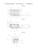
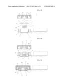
Patent application number: 20100072082
Inventors list |
Agents list |
Assignees list |
List by place |
Classification tree browser |
Top 100 Inventors |
Top 100 Agents |
Top 100 Assignees |
Usenet FAQ Index |
Documents |
Other FAQs |
Patent application title: Contact Lens Storage Case
Inventors:
Dong-Won Kang
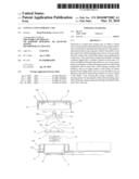
Agents:
THE WEBB LAW FIRM, P.C.
Assignees:
Origin: PITTSBURGH, PA US
IPC8 Class: AA45C1104FI
USPC Class:
206 51
Patent application number: 20100072082
Abstract:
Disclosed is a contact lens storage case, in which a contact lens is
automatically immersed in preserving solution when a cap is closed and is
automatically exposed out of the preserving solution when a cap is
opened, so that it is possible to store the contact lens without damage
and so that a user can easily hold the contact lens with his/her fingers
upon applying the contact lens. The contact lens storage case includes: a
storage container shaped like a cylinder, formed on both sides of a body,
and filled with preserving solution so as to store contact lenses or soft
lenses; a slider moving up and down while being assembled with an inner
side of the storage container and holding a lens on an upper surface of
the slider; an elastic means for providing elastic force to move the
slider in an up direction, the elastic means being formed on a lower
surface of the slider; a cap covering the storage container; and a
pressing means for pressing the slider and preventing separation of the
lens, the pressing means being assembled with an inner side of the cap.Claims:
1. A contact lens storage case for storing contact lenses, comprising:a
storage container shaped like a cylinder, formed on both sides of a body,
and filled with preserving solution so as to store contact lenses or soft
lensesa slider moving up and down while being inserted in an inner side
of the storage container and holding a lens on an upper surface of the
slideran elastic means for providing elastic force to move the slider in
an up direction,the elastic means being formed on a lower surface of the
slidera cap covering the storage container; anda pressing means for
pressing the slider and preventing separation of the lens, the pressing
means being assembled with an inner side of the cap.
2. The contact lens storage case as claimed in claim 1, wherein the storage container comprises a slider groove formed on the inner side of the storage container so as to prevent the slider moving up and down from moving more than a predetermined distance, and a side surface of the storage container is constructed with a dual structure having an inner wall and the outer wall to prevent the preserving solution placed in the storage container from leaking to an outside, so that the preserving solution is introduced into a space formed between the inner wall and the outer wall.
3. The contact lens storage case as claimed in claim 1, wherein the slider comprises:a slide protrusion engaged with the slider groove formed in the inner side of the storage container;a lens supporting probe having a convex shape for supporting the lens;a hole for allowing the preserving solution to easily move when the slider is immersed in the preserving solution for storing; anda latching projection.
4. The contact lens storage case as claimed in claim 1, wherein the cap comprises a water-stop plate and a water-collecting plate formed on the inner side of the cap, in which the water-stop plate prevents the preserving solution from overflowing out of the storage container, and the water-collecting plate collects the preserving solution to the space between the inner wall and the outer wall of the storage container.
5. The contact lens storage case as claimed in claim 1, wherein the pressing means includes a pressing protrusion integrally formed with the cap on the inner side of the cap, or a pressing cap easily assembled with the cap.
6. The contact lens storage case as claimed in claim 5, wherein the pressing cap comprises a fitting hole to be assembled with the cap, a supporter for supporting the fitting hole, and a stretcher formed between the supporter and surrounding the pressing cap in the up direction, in which a lower surface of the stretcher comprises an anti-moving protrusion downwardly protruding, a latching protrusion positioned between the latching projection of the slider, and a supporting plate.
7. The contact lens storage case as claimed in one of claims 1 to 6, wherein, when the cap is assembled with the storage container, the pressing means assembled with the inner side of the cap presses the slider inserted in the storage container and moves the slider in the down direction of the storage container 20 so that the slider is immersed in the preserving solution, and when the cap is separated from the storage container, the pressure applied to the slider is removed, and the slider receives elastic force by the elastic means and moves in the up direction of the storage container, so that the slider is exposed out of the preserving solution.
Description:
TECHNICAL FIELD
[0001]The present invention relates to a contact lens storage case, in which a contact lens is automatically immersed in preserving solution when a cap is closed and is automatically exposed out of the preserving solution when a cap is opened, so that it is possible to store the contact lens without damage and so that a user can easily hold the contact lens with his/her fingers upon applying the contact lens.
BACKGROUND ART
[0002]Contact lenses or soft lenses for correcting sight require a separate storage case for storing the lenses, in contrast to the general glasses, and require to be stored in washing solution or preserving solution in order to prevent the lens from hardening and to remove a by-product, such as protein, attached on a surface of the lens upon applying the lens. Therefore, lenses are put in a lens storage case divided into a right case and a left case, having the preserving solution, for storing the contact lenses or soft lenses. However, the above lens storage case has been inconvenient in that the user should dip his/her fingers into the preserving solution or use a separate instrument when applying the contact lenses.
DISCLOSURE OF INVENTION
Technical Problem
[0003]Therefore, the present invention has been made in view of the above-mentioned problems, and the present invention provides a contact lens storage case, in which a contact lens is automatically exposed out of preserving solution when a cap of the contact lens storage case is opened, so that a user can easily hold a contact lens with his/her fingers without dipping his/her fingers into the preserving solution or washing solution when applying contact lenses or soft lenses.
Technical Solution
[0004]In accordance with an aspect of the present invention, there is provided a contact lens storage case, which includes a storage container having a predetermined volume therein and a slider groove on an inner side wall thereof, a slider having a convex shape and assembled with an inner side of the storage container in which a side protrusion is engaged with a slider groove, an elastic means for supporting a lower surface of the slider, a cap for covering the storage container, and a pressing means rotatably assembled with the inner side of the cap for pressing the slider and preventing the separation of the contact lens. Therefore, when the cap is closed, the pressing means moves in a down direction so as to press the slider so that the contact lens placed on the slider is stored while being immersed in the preserving solution in the storage container, and when the cap is opened, the contact lens placed on the upper portion of the slider is exposed by the elastic means so that a user can easily hold the contact lens.
Advantageous Effects
[0005]In accordance with the contact lens storage case of the present invention, the contact lens moves while being placed on the slider moving up and down in the storage container, and the slider slides up and down according to opening and closing of the cap so that the contact lens are exposed out of the preserving solution or are immersed in the preserving solution. Therefore, the present invention allows the user to conveniently store and hold the contact lens.
[0006]Further, in accordance with the contact lens storage case of the present invention, the user can easily hold the contact lens immersed in the preserving solution, and the time requiring for applying the contact lens can be reduced, thereby minimizing pollution and damage to the contact lens.
[0007]Furthermore, in accordance with the contact lens storage case of the present invention, the pressing means perpendicularly presses the slider having the contact lens on the upper surface of the slider, even though the cap rotates, and also, the pressing means prevents the separation of the slider out of the contact lens. Therefore, the present invention solves the problem in that, when the cap is opened and closed, the contact lens moves toward an external side of the upper surface of the slider and is caught in an aperture, so that the contact lens is torn or damaged.
[0008]That is, in the present invention, the slider on which the contact lens is placed perpendicularly moves up and down, while the contact lens is prevented from moving toward the external side in the upper surface of the slider, thereby preventing damage to and breakage of the contact lens.
BRIEF DESCRIPTION OF THE DRAWINGS
[0009]FIG. 1 is a plane view illustrating a contact lens storage case according to the present invention;
[0010]FIG. 2 is a front side view illustrating a state where a cap of a contact lens storage case is opened according to the present invention;
[0011]FIG. 3 is a perspective view of a slider according to the present invention;
[0012]FIG. 4 is a plane view of a slider according to the present invention;
[0013]FIG. 5 is a cross-sectional view of a slider according to the present invention;
[0014]FIG. 6 is a perspective view of a pressing cap according to the present invention;
[0015]FIG. 7 is a plane view of a pressing cap according to the present invention;
[0016]FIG. 8 is a front side view of a pressing cap according to the present invention;
[0017]FIG. 9 is an exploded cross-sectional view illustrating a contact lens storage case employing a pressing cap according to the present invention;
[0018]FIG. 10 is a cross-sectional view illustrating a state where a cap of a contact lens storage case employing a pressing cap is opened according to the present invention;
[0019]FIG. 11 is a cross-sectional view illustrating an assembly state of a contact lens storage case employing a pressing cap according to the present invention;
[0020]FIG. 12 is a cross-sectional view illustrating an enlarged part of a contact lens storage case according to the present invention;
[0021]FIG. 13 is an exploded cross-sectional view illustrating a contact lens storage case employing a pressing protrusion according to the present invention;
[0022]FIG. 14 is a cross-sectional view illustrating a state where a cap of a contact lens storage case employing a pressing protrusion is opened according to the present invention; and
[0023]FIG. 15 is a cross-sectional view illustrating an assembly state of a contact lens storage case employing a pressing protrusion according to the present invention.
BEST MODE FOR CARRYING OUT THE INVENTION
[0024]A contact lens storage case for storing contact lenses includes a storage container 20 shaped like a cylinder, formed on both sides of a body 10, and filled with preserving solution so as to store contact lenses or soft lenses, a slider 50 moving up and down while being inserted in an inner side of the storage container 20 and holding a lens 70 on an upper surface of the slider 50, an elastic means 40 for providing elastic force to move the slider 50 in an up direction, the elastic means 40 being formed on a lower surface of the slider 50, a cap 30 covering the storage container 20, and a pressing means 60 for pressing the slider 50 and preventing separation of the lens 70, the pressing means 60 being assembled with an inner side of the cap 30. When the cap 30 is assembled with the storage container 20, the pressing means 60 assembled with the inner side of the cap 30 presses the slider 50 inserted in the storage container 20 and moves the slider 50 in the down direction of the storage container 20 so that the slider 50 is immersed in the preserving solution, and when the cap 30 is separated from the storage container 20, the pressure applied to the slider 50 is removed, and the slider 50 receives elastic force by the elastic means 60 and moves in the up direction of the storage container 20, so that the slider 50 is exposed out of the preserving solution.
Mode for the Invention
[0025]Hereinafter, exemplary embodiments of the present invention will be described with reference to the accompanying drawings.
[0026]FIG. 1 is a plane view illustrating a contact lens storage case according to the present invention, and FIG. 2 is a front side view illustrating an open state of a cap of a contact lens storage case according to the present invention.
[0027]Referring to FIGS. 1 and 2, a contact lens storage case according to the present invention is shaped like a cylinder, and includes a pair of storage containers 20 mounted on both sides of a body 10 and capable of being filled with preserving solution for storing the contact lens therein. The inside of the storage container includes a slider 50 holding the contact lens and easily moving the contact lens in up and down directions, and a cap 30 corresponding to the storage container 20 so that the storage container 20 is assembled with the cap 30 through the rotating the cap 30. At this time, a pressing means 60 is provided inside the cap 30 for moving the slider 50 included in the storage container 20 in the down direction. The pressing means 60 comes into contact with the slider 50, and presses the slider 50 when the cap 30 is assembled with the storage container 20 so as to move the slider 50 in the down direction to be immersed in the preserving solution. Here, it is preferred that the pressing means 60 includes a pressing cap 60a assembled with the cap 30 or a plurality of pressing protrusions 60b integrally formed with the cap 30.
[0028]Further, the present invention includes an elastic means 40 for providing elastic force to move the slider 50 in the up direction when the cap 30 is separated from the storage container 20. The elastic means 40 is positioned between the storage container 20 and the slider 50 inserted in the storage container 20. Here, the elastic means 40 is not limited to a spring used for the description of the present invention, but can be implemented by anything, such as rubber and sponges, capable of providing elastic force.
[0029]FIG. 3 is a perspective view of a slider 50 according to the present invention, FIG. 4 is a plane view of a slider 50 according to the present invention, and FIG. 5 is a cross-sectional view of a slider 50 according to the present invention.
[0030]Referring to FIGS. 3 to 5, the slider 50 is inserted in the storage container 20 to store the contact lens, and moves in the down direction of the storage container 20 when the cap 50 is assembled with the storage container 20 so as to be immersed in the preserving solution. The slider 50 includes a lens supporting probe 52 having a convex shape to support the contact lens, and a plurality of slide protrusions 51 on a side surface of the slider 50. Further, the slider 50 is formed with a hole 53 for easily moving the preserving solution when the slider is immersed in the preserving solution for storing the contact lens. Furthermore, the slider 50 is formed with a plurality of latching projections 54 on one side of the slider 50.
[0031]FIG. 6 is a perspective view of a pressing cap 60a, FIG. 7 is a plane view of a pressing cap 60a, FIG. 8 is a front side view of a pressing cap 60a according to the present invention, and FIG. 13 is an exploded sectional view illustrating a contact lens storage case employing a pressing protrusion 60b according to the present invention.
[0032]Referring to FIGS. 6, 7, 8, and 13, it is preferred that the pressing means 60 for pressing the slider 50 to be immersed in the preserving solution when the cap 30 is assembled with the storage container 20 is implemented by the pressing cap 60 or the pressing protrusion 60b.
[0033]The pressing cap 60a for pressing the slider 50 is assembled with the cap 30. The pressing cap 60a includes a fitting hole 61a used to be assembled with the cap 30, a supporter 62a for supporting the fitting hole 61a, and a plurality of stretchers 63a formed between the supporters 62a to surround the pressing cap 60a in the up direction. Further, the pressing cap 60a includes an anti-moving protrusion 64a downwardly protruding from a lower surface of the stretcher 63a and a latching protrusion 65a, and a supporting plate 66a formed between the latching projections 54 of the slider 50.
[0034]The plurality of pressing protrusions 60b is formed inside of the cap 30, and the length of the pressing protrusions 60b becomes longer as the pressing protrusions 60b are positioned in the exterior side, which is shaped like the contact lens inserted in the pressing cap.
[0035]As described above, the storage container 20 is assembled with the cap 30 having the pressing means 60, such as the pressing protrusion 60b or the pressing cap 60a, so that the slider 50 inserted in the pressing cap 60a moves in the down direction.
[0036]FIG. 9 is an exploded cross-sectional view illustrating a contact lens storage case employing a pressing cap 60a, FIG. 10 is a cross-sectional view illustrating a state where a cap of a contact lens storage case employing a pressing cap 60a is opened, FIG. 11 is a cross-sectional view illustrating an assembly state of a contact lens storage case employing a pressing cap, and FIG. 12 is a cross-sectional view illustrating an enlarged part of a contact lens storage case according to the present invention.
[0037]Referring to FIGS. 9 to 12, the contact lens storage case of the present invention includes the body 10, the storage container 20, the cap 30, the elastic means 40, the slider 50, and the pressing means 60. Here, it is preferred that the pressing means 60 is implemented by the pressing cap 60a. The body 10 includes the storage container 20 on both sides of the body 10, the storage container 20 includes the elastic means 40 and the slider 50 therein, and the cap 30 is assembled with the pressing cap 60a on an inner side of the cap 30. The storage container 20 is assembled with the cap 30 through rotation, sealing the container. At this time, the inner side of the storage container 20 includes a slider groove 21 for preventing the slider 50 moving up and down from moving more than a predetermined distance, and the slider groove 21 is engaged with the slide protrusion 51 formed on one side of the slider 50. As described above, there are provided a plurality of slide protrusions 51 and a plurality of slider grooves 21 so as to prevent the storage container 20 from separating to the outside of the storage container 20 when the slider moves by the elastic means 40. Further, when the slider 20 holds the contact lens 70 and downwardly moves, in order to prevent the preserving solution from leaking to the outside of the storage container 20, a side surface of the storage container 20 is constructed with a dual structure having an inner wall 20a and an outer wall 20b. A space between the inner wall 20a and the outer wall 20b is provided so that the preserving solution is introduced into the space when the slider 20 holding the contact lens 70 is immersed in the preserving solution, so as to prevent the preserving solution from leaking out of the storage container 20.
[0038]The inner side of the cap 30 includes a fitting protrusion 31 for fitting the pressing cap 60a, and a water-stop plate 32 being into contact with the inner wall 20a of the storage container 20 when the cap 30 is assembled with the storage container 20 and preventing the preserving solution from overflowing from the storage container 20. Further, the cap 30 includes a water stop groove 30b on the inner side of the cap 30, which is in contact with the inner wall 20a and the outer wall 20b of the storage container 20 so as to maintain the watertight. Further, the cap 30 includes a water collecting plate 30a positioned between the inner wall 20a and the outer wall 20b of the storage container 20 when the cap 30 is assembled with the storage container 20, so as to prevent the preserving solution overflowing from the storage container 20 from leaking to the outside along the cap 30. The water collecting plate 30a not only prevents the preserving solution from moving along the inner side of the cap 30, but also collects the preserving solution into the space between the inner wall 20a and the outer wall 20b.
[0039]The cap 30 described above is assembled with the pressing cap 60 downwardly moving the slider 50 inserted in the storage container 20. At this time, the fitting hole 61a formed on one side of the pressing cap 60a is fitted to the fitting protrusion 31 formed on the inner side of the cap 30 so that the cap 30 is assembled with the pressing cap 60a. The fitting protrusion 31 has a front end portion thicker than a back end portion so that the rotation of the pressing cap 60a is easily performed after the fitting protrusion 31 is fitted in the fitting hole 61a. This is for the purpose of preventing the slider 50 holding the contact lens 70 from rotating because the cap 30 is assembled with the storage container 20 through rotation in a state where the pressing cap 60a is assembled with the cap 30. The easily rotatable pressing cap 60a described above presses the slider 50 according to assembling the cap 30 and the storage container 20 so that the slider is immersed in the preserving solution. Further, the plurality of latching protrusions 65 is formed on one side of the pressing cap 60a so that the latching protrusions 65 are positioned between latching projections 54 of the slider 50 when the pressing cap 60a presses the slider 50. Further, the pressing cap 60a includes a plurality of supporting plates 66a so that the pressing cap 60a can press the slider 50 with uniform force. This is for the purpose of supporting the pressing cap 60a assembled by only the fitting hole 61a in such a manner that the plurality of supporting plates 66a comes into contact with the cap 30.
[0040]The contact lens storage case according to the present invention includes the elastic means 40 in the storage container 20, and the elastic means 40 upwardly moves the slider 50 so as to expose the slider 50 out of the preserving solution. At this time, the elastic means 40 is positioned between the storage container 20 and the slider 50, and provides elastic force for upwardly moving the slider 50 along the slider groove 21 formed on the inside of the storage container 20.
[0041]As described above, according to the contact lens storage case of the present invention, the preserving solution is placed in the storage container 20, the contact lens is placed on the lens supporting probe 52 of the slider 50 supported by the elastic means 40, and the storage container 20 is assembled with the cap 30 through the rotation of the cap 30. At this time, the pressing cap 60a assembled with the cap 30 presses the slider 50 and downwardly moves the slider 60, so that the slider comes to be immersed in the preserving solution. As described above, when the cap is separated from the storage container 20, the slider 50 immersed in the preserving solution by the pressing cap 60a moves upwardly by the compressed elastic means 40 so that the slider 60 is exposed out of the preserving solution, thereby allowing the user to easily hold the contact lens.
[0042]FIG. 13 is an exploded cross-sectional view illustrating a contact lens storage case employing a pressing protrusion 60b, FIG. 14 is a cross-sectional view illustrating a state where a cap of a contact lens storage case employing a pressing protrusion 60b is opened, and FIG. 15 is a cross-sectional view illustrating an assembly state of a contact lens storage case employing a pressing protrusion 60b according to the present invention.
[0043]Referring to FIGS. 12 to 14, the plurality of pressing protrusions 60b having the protrusion shape is formed in the inner side of the cap 30, and the pressing protrusions 60b become longer from a center portion to the outside, which is shaped like the contact lens inserted in the storage container 20.
[0044]The pressing protrusion 60b is integrally formed with the cap 30. Therefore, when the cap 30 is assembled with the storage container 20, the pressing protrusions 60b press the slider 50 holding the contact lens 70 so as to move the slider 50 in a down direction of the storage container 20.
[0045]As described above, in the contact lens storage case of the present invention, the elastic means 40 is inserted between the storage container 20 filled with the preserving solution and the slider 50, and the slider 50 is inserted in the storage container 20. At this time, the slide protrusion 51 formed on one side of the slider 50 is engaged with the slider groove 21 formed on the inner side of the storage container 20. The slider groove 21 is formed on the inner side of the storage container 20 so as to prevent the slider 50 from separating from the storage container 20 when the slider 50 moves up and down.
[0046]Further, when the cap 30 is assembled with the storage container 20, the plurality of pressing protrusions 60b formed on one side surface of the cap 30 presses the slider 50 so that the slider 50 moves in a down direction of the storage container 20, so as to be immersed in the preserving solution filled in the storage container. As described above, when the cap 30 is separated from the storage container 20 in the storage case having the contact lens 70, the pressure applied to the slider 50 by the pressing protrusions 60b formed on one side surface of the cap 30 is removed so that the slider 50 moves in the up direction of the storage container 20 by the pressed elastic means 40, to be exposed out of the preserving solution.
[0047]As described above, according to the contact lens storage case of the present invention, the slider 50 easily movable up and down is inserted in the storage container 20 filled with the preserving solution, the elastic means 40 is mounted between the slider 50 and the storage container 20 so as to provide the slider 50 with elastic force, and the storage container 20 having the elastic means 40 and the slider 50 therein is assembled with the cap 30 having the pressing means 60, so that the slider 50 is pressed by the pressing means 60, to be immersed in the preserving solution for storing. Further, when the cap 30 is separated from the storage container 20, the pressure applied to the slider 50 is removed and the slider 50 receives elastic force from the elastic means 40, so that the slider 50 moves in the up direction of the storage container 20, so as to be exposed out of the preserving solution, thereby allowing the user to easily hold the contact lens.
User Contributions:
comments("1"); ?> comment_form("1"); ?>Inventors list |
Agents list |
Assignees list |
List by place |
Classification tree browser |
Top 100 Inventors |
Top 100 Agents |
Top 100 Assignees |
Usenet FAQ Index |
Documents |
Other FAQs |
User Contributions:
Comment about this patent or add new information about this topic:
Images included with this patent application:
 |  |
 |  |
 |
| Similar patent applications: | |
| Date | Title |
|---|---|
| 2010-01-14 | Contact lens storage case |
| 2011-03-03 | Contact lens storage case |
| 2010-05-20 | Contact lens case |
| 2010-07-29 | Contact lens packages |
| 2011-03-31 | Contact lens case |
| New patent applications in this class: | |
| Date | Title |
|---|---|
| 2022-05-05 | Blister package for contact lens |
| 2016-09-01 | Contact lens storage system |
| 2016-07-14 | Methods, devices, and systems for moving wet ophthalmic lenses during their manufacture |
| 2016-07-14 | Contact lens dispensing container |
| 2016-04-14 | Contact lens case with cleaning compartment |
| New patent applications from these inventors: | |
| Date | Title |
|---|---|
| 2014-10-02 | Sensor node and reliable method for tracking boundary of continuous objects using assistance node in wireless sensor network |
| 2014-04-24 | Method for managing and sharing symmetric flow and asymmetric flow in duplexed network |
| 2014-04-24 | Method for managing and sharing symmetric flow and asymmetric flow in duplexed network |
| 2014-01-02 | Network application virtualization method and system |
| 2013-10-24 | Method of controlling traffic by time-based policy |
| Top Inventors for class "Special receptacle or package" | |
| Rank | Inventor's name |
|---|---|
| 1 | Donald E. Weder |
| 2 | Brett R. Glass |
| 3 | Daniel Lee Bizzell |
| 4 | Andrea Biondi |
| 5 | Nicole E. Glass |