Patent application title: Automotive wind powered generator
Inventors:
Timothy W. Kiler (Lake Worth, FL, US)
IPC8 Class: AF03D900FI
USPC Class:
290 55
Class name: Prime-mover dynamo plants fluid-current motors wind
Publication date: 2010-03-11
Patent application number: 20100060011
Inventors list |
Agents list |
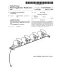
Assignees list |
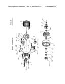
List by place |
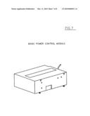
Classification tree browser |
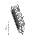
Top 100 Inventors |
Top 100 Agents |
Top 100 Assignees |
Usenet FAQ Index |
Documents |
Other FAQs |
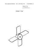
Patent application title: Automotive wind powered generator
Inventors:
Timothy W. Kiler
Agents:
ROBERT C. KAIN, JR.
Assignees:
Origin: SUITE 205, US
IPC8 Class: AF03D900FI
USPC Class:
290 55
Patent application number: 20100060011
Abstract:
The Wind Powered Generator System is a combination of many common
automotive parts. Automotive wind power is a new area and incorporates a
roof carrier system that have generators mounted on the crossbar or the
roof system. The air velocity or wind turns the fan blade when either
vehicle is in motion or not, producing an electrical current.Claims:
1. A wind powered generating system mounted on the roof of automotive
vehicles comprising: generators mounted on crossbar of roof carrier, air
velocity rotating a fan to produce electric current.Description:
BACKGROUND
[0001]1. Field
[0002]The present disclosure pertains to an automotive wind powered generator system.
[0003]2. Description of Related Art
[0004]Several automotive generators, power control module, battery and or cell unit. All of these components are parts of automotive vehicles.
[0005]The above mentioned components provide a power source for generating system provided by a drive belt system. None of these systems incorporate an outer wind power generating system for electric automotive vehicles.
BRIEF DESCRIPTION OF THE FIGURES
[0006]The present invention is illustrated by way of existing illustrations of components or parts and by drawings.
[0007]FIG. 1 illustrates the wind powered generator system for roof mounting.
[0008]FIG. 2 illustrates three different angles of the wind power generator.
[0009]FIG. 3 illustrates the fan blade used on the front of generator unit.
[0010]FIG. 4 illustrates a flow chart of the interconnections of components.
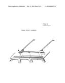
[0011]FIG. 5 illustrates the basic roof carrier and mountings located on the roof of vehicle.
[0012]FIG. 6 illustrates a basic breakdown diagram AC-Delco or General Motors `Delcotron` or generator.
[0013]FIG. 7 illustrates a basic General Motors Power Control Module.
[0014]FIG. 8 illustrates a basic General Motors Battery or Electronic Cell.
DETAILED DESCRIPTION
[0015]The following description provides an automotive wind powered generator system. In the following description, numerous specific details are set forth in order to provide a more thorough understanding of the present invention.
[0016]The present invention is an electrical re-charging station for hybrid or electric vehicles which contain a battery or electric cell. The purpose is to have an electric producing generator(s) or motor(s) consistently re-charging the battery or cell while the vehicle is in motion or in Park position. A fan blade placed on the rotor shaft or hub of the generator(s) will turn clockwise with the assistance of air velocity, thus producing an electrical current. The benefit is that the generator system will produce an electric current that will increase the possible "Range" of the vehicle. It will also charge enough voltage to reduce the amount for "At Home" charging from utilities.
[0017]The components necessary to assemble this system consist of a generator that is GM number 10495386, plastic fan blade that is Electrolux 5308000010, a roof-rack crossbar that is GM number 17801157, a power control unit that is GM number 16217058 and a battery or cell that is GM number 19168294.
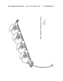
[0018]FIG. 1 illustrates the use of multiple generators on the crossbar. These generators can slide into several positions to "stagger" air flow when more than one crossbar is used on vehicle. It also illustrates the use of a protective cover used for rain, snow or other. The generators also have an electrical "pigtail" or connector to be snapped in the wiring harness. The wiring harness runs along the base of the crossbar.
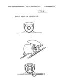
[0019]FIG. 2 illustrates three different angles of the generator. The frame or housing of this particular unit requires a plastic material. This will make the unit lighter and easier to re-locate. It will also be able to be produced in color(s) of the vehicle(s). The rear frame has ventilation "slots" to handle "air flow" velocity from fan intake area. The front frame and fan intake area is wide enough to place a 4 inch plastic fan that is Electrolux number 5308000010. To protect the fan from outside particles or debris is a wire screen. Then, of course, the protective cover to close over the fan intake area.
[0020]FIG. 3 illustrates the fan blade on the front of generator unit. This fan blade Electrolux SKU part number 5308000010 is 4 inches wide and turns the rotor clockwise to create electrical current.
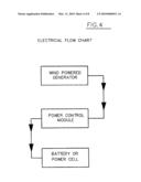
[0021]FIG. 4 illustrates the flow chart of the interconnection of components. From generator system to power control module to battery or cell. Also, the system is all integrated with a wiring harness.
[0022]FIG. 5 illustrates the basic roof carrier and mountings located on the roof of vehicle. The crossbar or carrier GM number 17801157, are removable, if necessary, and come with a lock and key system. The crossbar could be left on the roof for charging while vehicle is not in use.
[0023]FIG. 6 illustrates a breakdown diagram of a basic AC-Delco or General Motors `Delcotron` or generator. This diagram encompasses all components of an "Internal Voltage Regulator" style generator. Ford or Motorcraft have made generators with an "External Voltage Regulator". Depending upon usage of system, required voltage, and other variables, both styles could be used. The listing of the AC-Delco or GM part numbers is on the "Generator Components Sheet".
[0024]FIG. 7 illustrates a basic Power Control Module. As many control modules of today, GM part number 16217058, they are programmable. This module serves as a regulator, inverter, or emergency cut-off. The module controls the input of current to the battery or cell by regulating the output of the generator(s). This module controls the maximum voltage requirement. If the generators used for the system are not for a `12 Volt` system, it also serves as an inverter to 12 Volts. The system can be operated directly from generator system to battery or cell, but in vehicles of the day, there are too many variables not to have some sort of control module.
[0025]FIG. 8 illustrates a basic General Motors battery or cell, GM part number 19168294. There are many different electric cells, including lithium power cells. Some are called batteries; some are called electric power cells.
Specification
[0026]The Wind Powered Generator System is a charge and recharging system for Hybrid or Electric vehicles. The system charges the battery or electric cell by air velocity or wind. The system charges while the vehicle is in motion or in a `Park` position. The typical roof carrier system for vehicles include crossbars. On these crossbars, generators are mounted facing the front of vehicle with a fan blade on the front of the generator. As the vehicle moves forward, the fan blade turns the generators rotor with the wind creating an electrical current.
Generator Components Sheet
TABLE-US-00001 [0027]1. Rotor GM part number 10475405 2. Stator GM part number 1984584 3. Screw 4. Capacitor GM part number 1978146 5. Fan GM part number 1978057 6. Pulley GM part number 10457989 7. Washer GM part number 1941978 8. Shaft Nut GM part number 1911324 9. Collar GM part number 1978520 10. Frame GM part number 1985497 11. Slinger 12. Bearing GM part number 12339293 13. Collar GM part number 1978059 14. Plate GM part number 1971993 15. Screw GM part number 1975736 16. Washer 17. Nut GM part number 120622 18. Screw GM part number 14058081 19. Rectifier GM part number 1987061 20. Diode Trio GM part number 1985348 21. Bolt GM part number 1956975 22. Seal 23. Bearing GM part number 9441879 24. Terminal GM part number 1975471 25. Frame GM part number 1979754 26. Regulator GM part number 1116423 27. Washer 28. Screw GM part number 1876682 29. Spring GM part number 1964117 30. Brush GM part number 1984462 31. Washer 32. Screw GM part number 1876681 33. Resistor GM part number 830478 34. Collar GM part number 1978064
User Contributions:
comments("1"); ?> comment_form("1"); ?>Inventors list |
Agents list |
Assignees list |
List by place |
Classification tree browser |
Top 100 Inventors |
Top 100 Agents |
Top 100 Assignees |
Usenet FAQ Index |
Documents |
Other FAQs |
User Contributions:
Comment about this patent or add new information about this topic:
Images included with this patent application:
 |  |
 |  |
 |  |
 |  |
 |
| Similar patent applications: | |
| Date | Title |
|---|---|
| 2012-12-06 | Wave powered generator |
| 2010-09-23 | Oscillating power generator |
| 2011-01-20 | Wind power generator |
| 2011-01-20 | Submerged power generator |
| 2011-06-09 | Wind power generator |
| New patent applications in this class: | |
| Date | Title |
|---|---|
| 2022-05-05 | Wind turbine suitable for mounting on existing mast such as street lamp |
| 2018-01-25 | Modular multi-axial rotor |
| 2018-01-25 | Rotating sunlight/light beam for fractional/beneficial use |
| 2017-08-17 | Spacer for wind turbine cables |
| 2017-08-17 | Vertical axis wind turbines |
| Top Inventors for class "Prime-mover dynamo plants" | |
| Rank | Inventor's name |
|---|---|
| 1 | Henrik Stiesdal |
| 2 | Per Egedal |
| 3 | Akira Yasugi |
| 4 | Takatoshi Matsushita |
| 5 | Lowell L. Wood, Jr. |