Patent application title: FOLDING AND CUTTING APPARATUS
Inventors:
Brian J. Jacobs (Kennebunk, ME, US)
Eric J. Moberg (Sanford, ME, US)
IPC8 Class: AB65H3500FI
USPC Class:
156510
Class name: Adhesive bonding and miscellaneous chemical manufacture surface bonding means and/or assembly means therefor with cutting, punching, piercing, severing, or tearing
Publication date: 2010-02-25
Patent application number: 20100043983
Inventors list |
Agents list |
Assignees list |
List by place |
Classification tree browser |
Top 100 Inventors |
Top 100 Agents |
Top 100 Assignees |
Usenet FAQ Index |
Documents |
Other FAQs |
Patent application title: FOLDING AND CUTTING APPARATUS
Inventors:
Brian J. Jacobs
Eric J. Moberg
Agents:
CHRIS A. CASEIRO
Assignees:
Origin: PORTLAND, ME US
IPC8 Class: AB65H3500FI
USPC Class:
156510
Patent application number: 20100043983
Abstract:
An apparatus for folding and cutting tape, including Ultraflex® tape.
The apparatus includes a platform, which may be hinged for folding. A
tape roll retainer, tape roller, tape folder, folded tape guide, optional
meter and a cutter are removably affixed to the platform. The tape folder
is configured to cause automatic folding of the tape when directed
therethrough. The tape folder includes a pair of opposing folding
components that force the tape into a folded configuration.Claims:
1. An apparatus for folding, cutting and dispensing tape, the apparatus
comprising:a. a platform;b. a tape roll retainer affixed to the platform
and arranged to rotatably retain thereon a roll of tape;c. a tape folder
affixed to the platform, the tape folder including a first folding
component and a second folding component, wherein the first folding
component and the second folding component are spaced from one another
and arranged to cause tape passing through the tape folder to fold onto
itself without manual intervention;d. means affixed to the platform for
guiding folded tape from the tape folder; ande. a cutter for cutting
folded tape directed thereto from the means for guiding.
2. The apparatus as claimed in claim 1 further comprising a tape roller positioned between the tape roll retainer and the tape folder and arranged to direct tape from the roll of tape to the tape folder.
3. The apparatus as claimed in claim 1 further comprising a meter for measuring the length of folded tape passing to the cutting means.
4. The apparatus as claimed in claim 3 further comprising a wheel coupled to the meter and arranged to contact the folded tape.
5. The apparatus as claimed in claim 1 wherein the means for guiding includes a first guide angle and a second guide angle affixed to the platform.
6. The apparatus as claimed in claim 5 wherein the means for guiding further includes a retaining bar affixed between the first guide angle and the second guide angle.
7. The apparatus as claimed in claim 1 wherein the means for guiding is of adjustable width.
8. The apparatus as claimed in claim 1 wherein the first folding component of the tape folder is a first three-dimensional irregular convex hexagon rotatable about a first folding spindle that is affixed to the platform and the second folding component of the tape folder includes a second three-dimensional irregular convex hexagon and a third three-dimensional irregular convex hexagon, both of which are rotatable about a second folding spindle that is affixed to the platform.
9. The apparatus as claimed in claim 8 wherein the tape folder includes a folder centerline that substantially corresponds with the vertical alignment of tape entering the tape folder from the roll of tape, wherein the first three-dimensional irregular convex hexagon includes a vertex extending beyond the folder centerline in a first direction, the second three-dimensional irregular convex hexagon includes a vertex spaced above the vertex of the first three-dimensional irregular convex hexagon and extending beyond the folder centerline in a second direction opposite that of the vertex of the first three-dimensional irregular convex hexagon, and the third three-dimensional irregular convex hexagon includes a vertex spaced below the vertex of the first three-dimensional irregular convex hexagon and extending beyond the folder centerline in the second direction.
10. The apparatus as claimed in claim 1 wherein the platform is hinged to enable its folding.
Description:
BACKGROUND OF THE INVENTION
[0001]1. Field of the Invention
[0002]The present invention relates to devices used to fold and cut drywall tape. In particular, the present invention is related to devices to dispense, fold, measure and cut specialty drywall tapes including, but not limited to Ultraflex®. The present invention is a tape dispensing, folding, measuring and cutting apparatus.
[0003]2. Description of the Prior Art
[0004]Drywall tape is used to seal and blend the interface between sheetrock panels, including at angled interfaces. Drywall tape can also be used to seal soffit interfaces. In addition to conventional drywall tapes that have been available for many years, there exist specialty tapes that provide for particularly effective interface sealing. One example is the product Ultraflex® tape made available by Structus Building Technologies, Inc. of Bend, Oreg. This tape, and others like it, are useful in off-angle applications (both short and long runs) and can be used for long columns or soffits. The taping product is designed to cover large gaps, particularly for inside and outside corners.
[0005]The problem with this particular taping product is that it comes in big rolls and is very bulky. It must be rolled out and folded and then measured to desired length for final cutting to that length. This usually takes place on the floor and makes it difficult for the user to move from this operation back to a ladder, place the tape and then start the process over again for the next section to be laid up. Tape dispensers have generally been described, and there have been devices used to fold portions of tape for specific reasons. However, none have addressed the needs of convenient dispensation, folding of the tape, including specialty drywall tape, at a location of interest, accurate measurement of the dispensed tape and ease of cutting. Therefore, what is needed is an apparatus to facilitate the handling of rolled tape, the folding of the tape at a location of interest, the measuring and then the cutting of the tape.
SUMMARY OF THE INVENTION
[0006]It is an object of the present invention to provide an apparatus suitable for the handling of rolled tape, the folding of the tape at a location of interest, the measuring and then the cutting of the tape. The apparatus of the present invention is arranged for a placement on a raised surface, such as a table, so that the user may conveniently dispense the tape without the tape rolling back onto itself without the need for a second person to assist in the rolling out, and without requiring the user to perform the dispensing on the floor. The present invention includes a platform, which optionally may be foldable for ease of transport and placement on a selectable substrate. One or more guides are used to direct the tape in the course of its unrolling. The apparatus further includes folding means arranged to enable folding of the tape in half, or another selectable orientation, in the course of the dispensing and without any manual folding activity by the invention's user required. The invention further includes a cutting tool to allow the user to a selectable length. The invention optionally includes a metering component to enable the user to identify easily when the folded tape has been extended to the desired length.
[0007]The apparatus is arranged to facilitate the dispensation of tape, such as drywall tape, in a manner that substantially reduces the amount of time required to prepare the tape for application. The apparatus is particularly suited for use with tapes pre-oriented for folding, such as those including scoring or perforation, such as, for example, specialty drywall tapes, including Ultraflex® tape. It is to be understood that the invention is not limited thereto and may be used with tapes that are not so pre-oriented for folding. A single user may use the apparatus of the present invention to unroll a bulky roll of tape to a selectable length, fold that tape in the course of the dispensing, and measure and cut it at a desired length. These and other advantages of the present invention will become apparent upon review of the following detailed description, the accompanying drawings and the appended claims.
BRIEF DESCRIPTION OF THE DRAWINGS
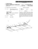
[0008]FIG. 1 is a perspective view of the dispensing, folding and cutting apparatus of the present invention.
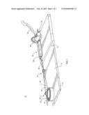
[0009]FIG. 2 is a first side view of the apparatus of the present invention.
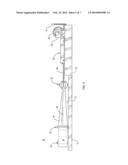
[0010]FIG. 3 is a second side view of the apparatus of the present invention.
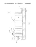
[0011]FIG. 4 is a first end view of the apparatus of the present invention.
[0012]FIG. 5 is a second end view of the apparatus of the present invention.
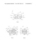
[0013]FIG. 6 is a top view of the folding component of the apparatus of the present invention.
[0014]FIG. 7 is an end view of the folding component of the present invention.
[0015]FIG. 8 is a side view of the folding component of the present invention.
[0016]FIG. 9 is a top view of the second guide component, optional meter and cutter of the apparatus.
DETAILED DESCRIPTION OF THE INVENTION
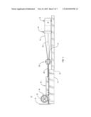
[0017]A folding, cutting and dispensing apparatus 10 of the present invention is shown in FIGS. 1-5. The apparatus includes a platform 12 with a top surface 13. The platform 12 may optionally include a hinge 15 so that the platform 12 may be foldable for ease of transport. The platform 12 and the other components of the apparatus 10 may be fabricated of one or more selectable materials chosen for suitability in the use of the apparatus 10.
[0018]The platform 12 is used for placement thereon of a tape roll 14 retained on a tape retaining means, such as a tape dowel 16 that allows rotation of the tape roll 14 while retained on the platform 12. The user pulls an end of unrolled tape 18 (before folding) through tape roller 20 to tape folder 22 and insertion into folded tape guide 24. Unrolled tape 18 includes a tape centerline 19. The tape roller 20 is shown as a pair of rollers, but can be any sort of device to facilitate movement of the tape 18 in a guided direction. The tape folder 22 is arranged as described herein to cause the tape 18 to fold substantially at its centerline or wherever the fold is desired when the tape 18 passes therethrough. The folded tape guide 24 may be of adjustable dimensions and includes a retaining bar 26 to ensure folded tape 28 remains substantially flat as it passes to tape meter 30. Tape meter 30 is arranged to detect and display the length of folded tape 28 passing under a wheel 32 as the folded tape 28 is pulled or otherwise moved manually or automatically toward cutter 34. When the tape meter 30 indicates the desired length of folded tape 28 has passed thereunder, the cutter 34 may be actuated to cut the folded tape 28. The user may then remove cut and folded tape 36 (shown in FIG. 9) and proceed with the step of applying the tape 36 where desired. The tape roll 14 remains in place ready for the next fold, measure and cut operation.
[0019]With continuing reference to FIGS. 1-5, the tape roll 14 may be of any width or type including, but not limited to, Ultraflex® tape. It is removably positioned on tape dowel 16, which is configured as a rotatable spindle that permits rolling out of tape 18 from the tape roll 14 while retaining the tape roll 14 substantially in position on the platform 12. The unrolled tape 18 passes around a first rotatable guide spindle 21 of tape roller 20 and to the inside of second rotatable guide spindle 23. One or more of the tape dowel 16, the first spindle 21 and the second spindle 23 may be arranged as a combination of a post removably affixable to the platform 12 at the top surface 13, and a retained roller bar that is free to spin about the post. It is to be understood that such components of the apparatus 10 may be arranged in other ways, provided they operate to permit rotatable movement of the tape roll 14 and guidance of the unrolled tape 18 to the tape folder 22.
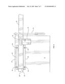
[0020]As illustrated in FIGS. 6-8, the tape folder 22 includes a first folding component 50 and a second folding component 52. The first folding component 50 includes a first three-dimensional irregular convex hexagon 53 having a center port 54 through which a first folding spindle 56 of the first folding component 50 is removably inserted. The first folding spindle 56 is affixable to the top surface 13 of the platform 12. The first folding component 50 is arranged for free rotation of the hexagon 53 about the first folding spindle 56 as the tape 18 passes through the tape folder 22. The first folding component 50 is configured and arranged so that a first primary vertex 58 of the hexagon 53 extends past a folder centerline 60 of the tape folder 22. This arrangement may be achieved by placement of the first folding spindle 56 on the platform 12 so that the first primary vertex 58 is positioned as indicated. Further, the folder centerline 60 is preferably substantially aligned with the tape centerline 19. The primary vertex 58 is aligned with first primary centerline 59.
[0021]With continuing reference to FIGS. 6-8, the second folding component 52 includes a second three-dimensional irregular convex hexagon 62 and a third three-dimensional irregular convex hexagon 64. The second irregular convex hexagon 62 is spaced from the top surface 13 of the platform 12 by the third irregular convex hexagon 64. The second three-dimensional irregular convex hexagon 62 has a center port 66 through which a second folding spindle 68 of the second folding component 52 is removably inserted. The second folding spindle 68 is affixable to the top surface 13 of the platform 12. The third three-dimensional irregular convex hexagon 64 has a center port 70 through which the second folding spindle 68 of the second folding component 52 is removably inserted.
[0022]The second folding component 52 is arranged for free rotation of the second hexagon 62 and the third hexagon 64 about the second folding spindle 68 as the tape 18 passes through the tape folder 22. The second hexagon 62 is configured with a second primary vertex 72 that extends past folder centerline 60 of the tape folder 22. The second primary vertex 72 is aligned with second primary centerline 73. The third hexagon 64 is configured with a third primary vertex 74 that extends past folder centerline 60 of the tape folder 22. The third primary vertex 74 is aligned with third primary centerline 75. This arrangement may be achieved by placement of the second folding spindle 68 on the platform 12 so that the second primary vertex 72 is above the third primary vertex 74. More specifically, the first vertex 58 of the first hexagon 53 extends beyond the folder centerline 60 in a first direction, the second vertex 72 of the second hexagon 62 is spaced above the first vertex 58 and extends beyond the folder centerline 60 in a second direction opposite that of the first vertex 58 of the first hexagon 53. In addition, the third vertex 74 of the third hexagon 64 is spaced below the first vertex 58 and extends beyond the folder centerline 60 in the second direction.
[0023]In operation, the tape folder 22 performs the function of automatically folding the tape 18 as it passes through. This folding is achieved by the arrangement of the three hexagons with respect to one another. The tape 18 is guided to the tape folder 22 in a way that makes its width dimension is substantially aligned with the folder centerline 60. As the tape 18 reaches the tape folder 22, it is forced into space 80, with the first primary vertex 58 forcing the tape centerline 19 in one direction, such as to the right when viewed from the tape's perspective in FIG. 7. At the same time, the second primary vertex 72 directs an upper portion of the tape 18 in the opposing direction (to the left in this example) and the third primary vertex 74 directs a lower portion of the tape 18 in the same opposing direction (again, in this example, to the left). As the tape 18 exits the tape folder 22, it exits as the folded tape 28, with its upper and lower ends in proximity to one another and the tape centerline 19 at the opposing side thereof As the folded tape 28 passes under the retaining bar 26, it is further folded such that the two halves of the folded tape 28 are substantially in contact with one another. It is to be noted that the first folding component 50 and the second folding component 52 may be positioned in a variety of selectable ways with respect to one another so that the tape 18 may be folded in different ways, such as other than substantially into two substantially equal halves. Further, the first folding component 50 and the second folding component 52 may be re-oriented so that they switch locations in order to enable folding of the tape 18 in the opposite direction. Those of ordinary skill in the art will recognize that these and other orientation changes may be achieved with the present invention.
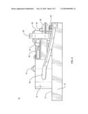
[0024]As illustrated in FIG. 9, the folded tape 28 is guided to folded tape guide 24, which includes first guide angle 80 and second guide angle 82, both of which are removably affixable to the top surface 13 of platform 12. The retaining bar 26 is removably affixed to the first guide angle 80 and the second guide angle 82 and spaced slightly above the top surface 13 of the platform 12 such that the folded tape 28 passing thereunder is pressed to be substantially flat. The platform 12 may be of differing heights along its length, such as shown in the drawings, so that folded tape 28 exiting the tape folder 22 is substantially on the same plane entering the folded tape guide 24. Alternatively, the platform 12 may be of constant height along its entire length and the folded tape 28 may or may not remain on the same plane exiting the tape folder 22 as entering the folded tape guide 24. The folded tape guide 24 is of selectable dimensions, including of selectable width dimension, by selection of the ports of the platform 12 used to removably affix the first guide angle 80 and the second guide angle 82 to the platform 12, such as attachment ports 84.
[0025]With continuing reference to FIG. 9, the folded tape 28 passes from folded tape guide 24 under wheel 32, which is used to establish a frictional engagement with the folded tape 28 to facilitate dispensation of the tape 18 from the roll 14. Additionally, the wheel 32 is coupled to meter 30 such that rotational movement of the wheel 32 is translated into a measure of the length of folded tape 28 passing under the wheel 32. That measure may be used to determine the length of folded tape 28 dispensed and, therefore, the point on the folded tape 28 at which cutting occurs by actuation of cutter 34 to produce cut and folded tape 36 of a desired length. The meter 30 is removably affixable to the platform 12 and the wheel 32 is removably affixable to the meter and/or the platform 12. The cutter 34 is removably affixable to the platform 12 and may be of the type used to cut lengths of paper precisely. The meter 30 and wheel 32 may be coupled parts of the Lufkin® Pro Series measuring wheel, Pro Series model no. PSMW18 available from Cooper Hand Tools of Apex, N.C., without the handle. The cutter 34 may be a portion of the X-acto® plastic trimmer model 26232 available from Elmer's Products, Inc. of Columbus, Ohio.
[0026]The folding, cutting and dispensing apparatus 10 is shown and described herein as a substantially manually operated device that greatly facilitates the process of dispensing and folding the tape 18. However, it is contemplated that the apparatus 10 may include one or more steps that are conducted automatically. For example, a means for drawing the tape 18 from the roll 14 to the cutter 34 may be an automated puller coupled to computing means arranged to specify the length of folded tape 36 desired. Upon activation, the automated puller would initiate tape pulling and would cause the cutter 34 to actuate and cause a cutting event to occur upon receipt of a communication from the meter 30 that the designated length of folded tape 28 has been reached. Additionally, automated communicating means may form part of the invention, such as by wired or wireless signal exchange from the user, who would determine a length of folded tape needed from a location spaced away from the apparatus 10, and then transmit a signal with that information to the apparatus 10, such as to the automated puller or the computing means. Upon receipt of that signal, the computing means or automated puller would initiate the process of tape pulling, measuring and cutting.
[0027]The present invention has been described with respect to a specific preferred embodiment. Nevertheless, it is to be understood that various modifications may be made without departing from the spirit and scope of the invention. All equivalents are deemed to fall within the scope of this description of the invention as set out in the following claims.
User Contributions:
comments("1"); ?> comment_form("1"); ?>Inventors list |
Agents list |
Assignees list |
List by place |
Classification tree browser |
Top 100 Inventors |
Top 100 Agents |
Top 100 Assignees |
Usenet FAQ Index |
Documents |
Other FAQs |
User Contributions:
Comment about this patent or add new information about this topic:
Images included with this patent application:
 |  |
 |  |
 |  |
 |  |
| Similar patent applications: | |
| Date | Title |
|---|---|
| 2012-05-24 | Method for producing jointed member and friction stir welding apparatus |
| 2009-12-03 | Cutting method and cutting apparatus |
| 2009-03-12 | Adhesive chuck and substrate bonding apparatus |
| 2010-02-04 | Bonding method and bonding apparatus |
| 2010-02-25 | Method of building carcass band and stitcher apparatus |
| New patent applications in this class: | |
| Date | Title |
|---|---|
| 2022-05-05 | Tape lamination machine scrap collection assembly |
| 2016-06-16 | Secondary groove for work piece retention during machining |
| 2016-02-25 | Gluing device |
| 2015-11-19 | Systems for forming a ceramic matrix composite structure, and related advanced fiber placement apparatuses |
| 2015-03-05 | Device for forming separation starting point, stack manufacturing apparatus, and method for forming separation starting point |
| Top Inventors for class "Adhesive bonding and miscellaneous chemical manufacture" | |
| Rank | Inventor's name |
|---|---|
| 1 | Maurizio Marchini |
| 2 | Gianni Mancini |
| 3 | Shou-Shan Fan |
| 4 | Takuya Nakazono |
| 5 | Kartik Ramaswamy |