Patent application title: Height adjustable stand for notebook computer
Inventors:
Chio Lin Ou (Changhua, TW)
IPC8 Class: AF16M1100FI
USPC Class:
248676
Class name: Supports machinery support stand
Publication date: 2010-01-21
Patent application number: 20100012815
Inventors list |
Agents list |
Assignees list |
List by place |
Classification tree browser |
Top 100 Inventors |
Top 100 Agents |
Top 100 Assignees |
Usenet FAQ Index |
Documents |
Other FAQs |
Patent application title: Height adjustable stand for notebook computer
Inventors:
Chio Lin Ou
Agents:
SAM CHEN
Assignees:
Origin: TAIPEI, TW
IPC8 Class: AF16M1100FI
USPC Class:
248676
Patent application number: 20100012815
Abstract:
A stand structure includes a stand having two side walls; and two
actuation mechanisms comprising an assembly for lifting and pushing the
stand and a link pivotably interconnecting the assembly for lifting and
pushing the stand and either side wall, and a bent member having a
handle, the bent member being adapted to pivotably interconnect the
assembly for lifting and pushing the stand and either side wall. Pivoting
the handle in a first direction will lift the stand a first predetermined
distance and push the stand a second predetermined distance. The
invention can increase a space below the stand significantly so as to
effectively dissipate heat when a notebook computer placed upon the stand
is in use.Claims:
1. A stand structure comprising:a stand having two side walls; andtwo
actuation mechanisms comprising means for lifting and pushing the stand
and a link pivotably interconnecting the means for lifting and pushing
the stand and either side wall, and a bent member having a handle, the
bent member being adapted to pivotably interconnect the means for lifting
and pushing the stand and either side wall;whereby pivoting the handle in
a first direction will lift the stand a first predetermined distance and
push the stand a second predetermined distance.
2. The stand structure of claim 1, wherein the bottoms of the stand and the means for lifting and pushing the stand are flush when placing upon a flat support surface.
3. The stand structure of claim 1, wherein the first predetermined distance is about half the height of the means for lifting and pushing the stand.
4. The stand structure of claim 1, wherein the means for lifting and pushing the stand comprises two rectangular plates.
5. The stand structure of claim 1, wherein the means for lifting and pushing the stand is a rectangular plate.
6. The stand structure of claim 1, further comprising a recess formed on either side wall of the stand.
Description:
BACKGROUND OF THE INVENTION
[0001]1. Field of Invention
[0002]The invention relates to notebook computer stands and more particularly to such a stand assembly having a height adjustable mechanism in order to facilitate heat dissipation of a notebook computer rested thereon by lifting the stand to increase a space below the stand by pivoting a handle in use.
[0003]2. Description of Related Art
[0004]Notebook computers are gaining popularity worldwide. Many people use notebook computers as the most important device of a so-called mobile office.
[0005]It is known that substantial heat is generated by a notebook computer in use. Internal fan of a notebook computer may partially solve the heat dissipation problem. Hence, how to effectively dissipate heat generated by a notebook computer in use has been an issue to be solved. A number of stands for notebook computer are commercially available. However, their uses are not convenient and further their heat dissipation feature is poor. Thus, the need for improvement still exists.
SUMMARY OF THE INVENTION
[0006]It is therefore one object of the invention to provide a stand assembly having a height adjustable mechanism in order to facilitate heat dissipation of a notebook computer rested thereon by lifting the stand to increase a space below the stand by pivoting a handle.
[0007]The above and other objects, features and advantages of the invention will become apparent from the following detailed description taken with the accompanying drawings.
BRIEF DESCRIPTION OF THE DRAWINGS
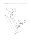
[0008]FIG. 1 is a fragmentary exploded view of a first preferred embodiment of stand assembly for notebook computer according to the invention;
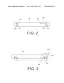
[0009]FIG. 2 is a side elevation of the assembled stand assembly in an inoperative position;
[0010]FIG. 3 is a view similar to FIG. 2 where the handle has been pivoted clockwise to lift the stand assembly and push forward same;
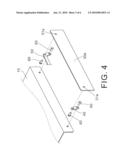
[0011]FIG. 4 is a fragmentary exploded view of a second preferred embodiment of stand assembly for notebook computer according to the invention;
[0012]FIG. 5 is a side elevation of the assembled stand assembly of FIG. 4 in an inoperative position;
[0013]FIG. 6 is a view similar to FIG. 5 where the handle has been pivoted clockwise to lift the stand assembly and push forward same;
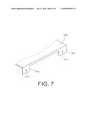
[0014]FIG. 7 is a fragmentary perspective view of another configuration of the stand of either embodiment; and
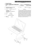
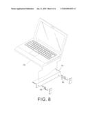
[0015]FIG. 8 is a view similar to FIG. 1 showing a notebook computer to be mounted on the stand.
DETAILED DESCRIPTION OF THE INVENTION
[0016]Referring to FIGS. 1 to 3, a stand assembly in accordance with a first preferred embodiment of the invention comprises the following components as discussed in detail below.
[0017]A stand 10 of inverted U has two spaced holes 111 on either side wall 11. Two actuation mechanisms 20 each is mounted on either side wall 11 of the stand 10.
[0018]At either side of the stand 10, the actuation mechanism 20 comprises two rectangular plates 30 having a hole 31; a flat, elongated link 40 having a first through hole 41 proximate one end and a second through hole 42 proximate the other end; a bent member 50 having one section 53 as a handle 53 and the other section as a link having a first through hole 51 proximate one end and a second through hole 52 at the joining portion of the two sections; and a plurality of (e.g., four pins) 60.
[0019]A first pin 60 is driven through the second through hole 52 into the hole 31 of one plate 30, a second pin 60 is driven through the first through hole 51 into one hole 111, a third pin 60 is driven through the second through hole 42 into the hole 31 of the other plate 30, a fourth pin 60 is driven through the first through hole 41 into the other hole 111 to pivotably secure the plates 30 to the side walls 11 via the link 40 and the bent member 50.
[0020]The bottoms of the side walls 11 of the stand 10 and the plates 30 are flush and are rested upon a support surface (e.g., desk (not shown)) as shown in FIG. 2. In use an individual may pivot the handle 53 clockwise until being stopped to lift the stand 10 above the support surface a predetermined distance and push the stand 10 forward a small predetermined distance due to the pivotal interconnections of the plates 30, the side walls 11, the link 40, and the bent member 50 as shown in FIG. 3. As a result, a space below the stand 10 is increased significantly so as to sufficiently dissipate heat. Preferably, the lifted predetermined distance is about half the height of the plate 30.
[0021]Referring to FIGS. 4 to 6, a stand assembly in accordance with a second preferred embodiment of the invention is shown. The second embodiment is identical to the first embodiment, except that the plates 30 of the first embodiment are replaced by a rectangular plate 30a having front and rear holes 31a.
[0022]The bottoms of the stand 10 and the plate 30a are flush and are rested upon a support surface (e.g., desk (not shown)) as shown in FIG. 5. In use an individual may pivot the handle of the bent member 50 clockwise until being stopped to lift the stand 10 above the support surface a predetermined distance and push the stand 10 forward a small predetermined distance due to the pivotal interconnections of the plate 30, the stand 10, the link 40, and the bent member 50 as shown in FIG. 6. As a result, a space below the stand 10 is increased significantly so as to sufficiently dissipate heat. Preferably, the lifted predetermined distance is about half the height of the plate 30a.
[0023]Referring to FIG. 7, another configuration of the stand 10a of either embodiment is shown. The stand 10a has two rectangular legs 11a on either side, each leg 11a having a through hole 111. That is, a rectangular recess is formed on either side wall of the stand 10a.
[0024]Referring to FIG. 8, it shows a notebook computer 70 to be mounted on the stand 10.
[0025]It is envisaged by the invention that a sufficient heat dissipation can be effected by the stand assembly of either embodiment of the invention.
[0026]While the invention herein disclosed has been described by means of specific embodiments, numerous modifications and variations could be made thereto by those skilled in the art without departing from the scope and spirit of the invention set forth in the claims.
User Contributions:
comments("1"); ?> comment_form("1"); ?>Inventors list |
Agents list |
Assignees list |
List by place |
Classification tree browser |
Top 100 Inventors |
Top 100 Agents |
Top 100 Assignees |
Usenet FAQ Index |
Documents |
Other FAQs |
User Contributions:
Comment about this patent or add new information about this topic:
Images included with this patent application:
 |  |
 |  |
 |  |
 |
| Similar patent applications: | |
| Date | Title |
|---|---|
| 2009-07-09 | Adjustable notebook computer support |
| 2008-10-02 | Multi-positionable notebook computer case |
| 2010-02-18 | Adjustable caster of indoor cook stove |
| 2010-05-06 | Height adjustment apparatus for projector |
| 2011-08-18 | Height and tilt adjustable keyboard support |
| New patent applications in this class: | |
| Date | Title |
|---|---|
| 2016-06-23 | A hand-held power tool and attachments |
| 2016-04-07 | Generator stand |
| 2015-10-22 | Gun holster system |
| 2015-04-02 | Device for supporting domestic appliances |
| 2014-10-23 | Storage and charging station for electronic appliances |
| Top Inventors for class "Supports" | |
| Rank | Inventor's name |
|---|---|
| 1 | Jeffrey D. Carnevali |
| 2 | Yun-Lung Chen |
| 3 | Wen-Tang Peng |
| 4 | Zheng-Heng Sun |
| 5 | Zhan-Yang Li |