Patent application title: One-piece fluid suctioning device
Inventors:
Craig R. Mccrary (Valencia, CA, US)
Thomas R. Thornbury (Los Angeles, CA, US)
Arnold M. Heyman (Los Angeles, CA, US)
IPC8 Class: AA61M106FI
USPC Class:
604 73
Class name: Means for introducing or removing material from body for therapeutic purposes (e.g., medicating, irrigating, aspirating, etc.) treating material introduced into or removed from body orifice, or inserted or removed subcutaneously other than by diffusing through skin means forceably introducing or removing material from body orifice or wound
Publication date: 2010-01-14
Patent application number: 20100010435
Inventors list |
Agents list |
Assignees list |
List by place |
Classification tree browser |
Top 100 Inventors |
Top 100 Agents |
Top 100 Assignees |
Usenet FAQ Index |
Documents |
Other FAQs |
Patent application title: One-piece fluid suctioning device
Inventors:
Craig R. McCrary
Thomas R. Thornbury
Arnold M. Heyman
Agents:
WILLIAM W. HAEFLIGER
Assignees:
Origin: PASADENA, CA US
IPC8 Class: AA61M106FI
USPC Class:
604 73
Patent application number: 20100010435
Abstract:
A mucous suction device, comprising in combination, a longitudinally
elongated, generally tubular, one-piece plastic body, the body having an
axially elongated tapered, first portion extending toward an inlet
proximate one end of the body, the body having an axially elongated
second portion extending toward an outlet proximate an opposite end of
the body, radially outwardly extending annular retention rings in said
body second portion, said rings having sharp annular peripheries and said
rings being axially resiliently flexible and axially spaced apart, and
there being body side porting between said body first and second
portions, said side porting being manually controllable to control
suction exertion.Claims:
1. A mucous suction device, comprising in combination:a) a longitudinally
elongated, generally tubular, one-piece plastic body,b) said body having
an axially elongated tapered, first portion extending toward an inlet
proximate one end of the body,c) said body having an axially elongated
second portion extending toward an outlet proximate an opposite end of
the body,d) radially outwardly extending annular retention rings on said
body second portion, said rings having sharp annular peripheries and said
rings being axially resiliently flexible and axially spaced apart,e) and
there being body side porting between said body first and second
portions, said side porting being manually controllable to control
suction exertion.
2. The combination of claim 1 wherein the body has a bore extending between said inlet and outlet, said bore having substantially constant diameter along entire body length.
3. The combination of claim 1 wherein said rings are axially flexible at said peripheries for establishing annular seals in response to axial reception of a connector tubing bore onto and over said body second portion.
4. The combination of claim 1 including a connector tubing having a bore received onto and over said body second portion, said bore having interference engagement with at least three of said rings, whereby said three rings are flexed axially at said peripheries thereof to establish annular seals.
5. The combination of claim 3 wherein said body portion and said rings consist of molded plastic material.
6. The combination of claim 1 wherein said rings have front and back flanks, and wherein for each pair of successive rings, the back flank of one ring of the pair is everywhere spaced axially from the front flank of the other ring of the pair whereby each ring is independently axially flexible.
7. The combination of claim 5 wherein said body portions are translucent.
8. The combination of claim 1 wherein said inlet faces axially endwise.
9. The combination of claim 1 wherein said inlet faces sidewise relative to said body elongated second portion.
10. The combination of claim 9 wherein said inlet has elongated length ll in the length direction of said body elongated first portion, and has narrowed with wl along said length ll, and wherein ll>>wl.
11. The combination of claim 1 wherein the body has a mid-portion between said first and second portions, said side porting located at said body mid-portion, there being a sideward protrusion integral with said mid-portion, said protrusion defining a finger controllable air inlet in communication with said side porting.
12. A suctioning device comprising in combination:a) an elongated, generally tubular, plastic body,b) said body having an axially elongated tapered, first portion extending toward an inlet proximate one end of the body,c) said body having an axially elongated second portion extending toward an outlet proximate an opposite end of the body,d) radially outwardly extending annular retention rings in said body second portion, said rings having sharp annular peripheries and said rings being axially resiliently flexible and axially spaced apart,e) and there being body side porting between said body first and second portions, said side porting being manually controllable to control suction exertion,f) said rings being axially flexible at said peripheries for establishing annular seals in response to axial reception of a connector tubing bore onto and over said body second portion.
13. The combination of claim 12 including a connector tubing having a bore received onto and over said body second portion, said bore having interference engagement with at least three of said rings, whereby said three rings are flexed axially at said peripheries thereof to establish annular seals.
14. The combination of claim 12 wherein said rings have front and back flanks, and wherein for each pair of successive rings, the back flank of one ring of the pair is everywhere spaced axially from the front flank of the other ring of the pair whereby each ring is independently axially flexible.
15. The combination of claim 12 wherein said inlet faces axially endwise.
16. The combination of claim 12 wherein said inlet faces sidewise relative to said body elongated second portion.
17. The combination of claim 16 wherein said inlet has elongated length ll in the length direction of said body elongated first portion, and has narrowed with wl along said length ll, and wherein ll>>wl.
18. The combination of claim 12 wherein the body has a bore extending between said inlet and outlet, said bore having substantially constant diameter along entire body length.
19. The combination of claim 6 wherein the back flanks extend at angles α relative to the axially elongated direction and the front flanks extend at angles β>α, and α>45.degree., and said second portion has a conical surface from which said rings project outwardly.
Description:
BACKGROUND OF THE INVENTION
[0001]This invention relates generally to medical suctioning or aspiration devices and methods, and more particularly to an improved device and method characterized by increased overall utility, as well as ease and effectiveness of use and operation.
[0002]There is need for improvements in devices of the type referred to above. Also, there is need for devices and methods embodying the novel and unusual features of construction, modes of operation and results found in the device and methods of use embodied in the present invention. This invention improves upon the devices of U.S. Pat. Nos. 6,958,050 and 4,729,765.
SUMMARY OF THE INVENTION
[0003]It is a major object of the invention to provide an improved suctioning device and method of its use, as referred to. Basically, the device comprises:
[0004]a) a longitudinally elongated, generally tubular, one-piece plastic body,
[0005]b) the body having an axially elongated tapered, first portion extending toward an inlet proximate one end of the body,
[0006]c) the body having an axially elongated second portion extending toward an outlet proximate an opposite end of the body,
[0007]d) radially outwardly extending annular retention rings on said body second portion, said rings having sharp annular peripheries and the rings being axially resiliently flexible and axially spaced apart,
[0008]e) and there being body side porting between said body first and second portions, the side porting being manually controllable to control suction exertion.
[0009]Another object is to provide a body bore that has constant, i.e. unstepped, diameter between the inlet and outlet, and to provide the rings to have axially flexible molded plastic peripheries for establishing annular seals in response to axial reception of a connector tubing bore onto and over the body second portion. In this regard, the connector tubing that fits over the rings has a bore with interference engagement with at least three of said rings, whereby those three rings are flexed axially at their peripheries, thereby to establish annular seals. The rings are typically axially spaced apart on a body conical surface whereby each ring is independently axially flexible, the rings closer to the body first portion being flexed to greater extent than other rings, to establish greater local retention to the connector tubing. Accordingly, the degree of such retention can be more accurately controlled by and in response to the degree of push-on advancement of that tubing relative to the rings.
[0010]A further object is to provide the rings to have front and back flanks, and wherein for each pair of rings, the successive back flank of one ring of the pair is everywhere spaced axially from the front flank of the other ring of the pair whereby each ring is independently axially flexible. Typically, the back flanks extend at angles α relative to the axially elongated direction and the front flanks extend at angles β relative to the axially elongated direction, and wherein β>α and α>45°, and said body second portion has a conical surface from which the rings project outwardly.
[0011]Yet another object is to provide a body side wall inlet to have elongated length ll in the length direction of the tubing elongated first portion, and has narrowed width wl along said length ll, and wherein ll>>wl.
[0012]These and other objects and advantages of the invention, as well as the details of an illustrative embodiment, will be more fully understood from the following specification and drawings, in which:
DRAWING DESCRIPTION
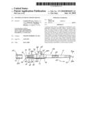
[0013]FIG. 1 is a side elevation view of a preferred device incorporating the invention;
[0014]FIG. 2 is an end view taken on lines 2-2 of FIG. 1;
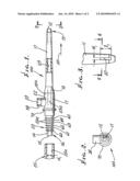
[0015]FIG. 3 is a top plan view taken on a modified device stem, showing a side inlet;
[0016]FIG. 4 is a section taken on lines 4-4 of FIG. 3;
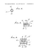
[0017]FIG. 5 is an enlarged fragmentary section, showing retention rings in the body and having peripheries engaging and being progressively and controllably flexed by engagement with the bore and connector tubing;
[0018]FIG. 6 is a still further enlarged section showing the angular relationships between ring front and rear flanks.
DETAILED DESCRIPTION
[0019]The drawings show the improved and preferred multi-purpose medical suctioning device 100, which is of one-piece, integrally molded synthetic resinous (plastic) composition. It includes:
[0020]a) a longitudinally and axially elongated, generally tubular, one-piece plastic body 10,
[0021]b) the body 10 having an axially elongated, tapered, first portion 11 extending toward an inlet 12 proximate an end 13 of the body, to receive fluid being suctioned,
[0022]c) the body 10 having an axially elongated second portion 14, extending from an outlet 15 proximate an opposite end 16 of the body, and toward a body mid-portion 17,
[0023]d) radially outwardly extending annular retention and sealing rings 20 on the body second portion 14, the thin rings having narrow and sharp annular peripheries 20a, and being axially stiffly resilient, and axially spaced apart,
[0024]e) and the body having side porting 22 at the mid porting 17, and being manually or finger controllable to control suction exertion.
[0025]It will be seen that the body preferably has a continuous bore 23 extending between the body opposite ends 13 and 16, the bore having constant or substantially constant, unstepped diameter along the entire body length between such steps, whereby flow of suctional fluid is unimpeded, through the body and to connector tubing. Such tubing is shown at 25 in FIG. 1 before its push-on connection over rings 20, and also in FIG. 5 after such push-on connection.
[0026]It will be noted that the rings are resiliently axially flexible, particularly at their peripheries 31, for establishing annular seals in response to axial reception, i.e. push-on, of the bore 25a of tubing 25 over the rings. The ring peripheries progressively increase in diameter, in the push-on direction 32, whereby the progressively forwardmost rings flex to greater progressive extent, for gripping the tubing bore, as seen in FIG. 5. Accordingly, the degree of gripping can be accurately controlled by the extent of push-on of the tubing, whereas, all or substantially all of the rings sub-tended by the connector tubing engage its bore to establish sealing at multiple locations, safe and full suctioning thereby being assured. The structure also accommodates tubing bore diameters that vary.
[0027]Note also in FIG. 6 that the rings have front flanks 36, and back flanks 37. For each pair of successive rings, as for example at 20a and 20b, the back flank 37 of ring 20b is everywhere spaced axially from the front flank 36 of ring 20a, whereby each ring is independently axially flexible, maintaining or enhancing the integrity of the sealing and anchoring (gripping) function and results, for differing connector bore diameters. As shown in FIG. 6, the bank flanks extend at angles α relative to the axially elongated direction and the front flanks extend at angles β relative to the axially elongated direction, and wherein β>α, and α>45°, and said second portion 14 has a conical surface from which said rings project outwardly.
[0028]The body 10 mid-portion has an integrally molded sidewise or transversely extending protrusion 38 defining a finger controllable air inlet 39 in communication with the side port 22. The body wall at 10a has substantially increased thickness outwardly from bore extent 23a at the body mid portion. This establishes a non flexible anchor region for manual gripping, which the body first portion 11 remain sidewise flexible to accommodate to the geometry of the anatomy, such as the mouth, being suctioned.
[0029]It will be noted that in FIGS. 1 and 2 the inlet 12 faces axially endwise, in the direction indicated by arrow 50.
[0030]In the FIGS. 3 and 4 modification, the inlet or inlets 52 face sidewise, i.e. transversely relative to the longitudinally axial extent of the body first portion 11 shown. Each such inlet preferably has elongated length ll in the longitudinal direction of 11, and has narrowed width wl along the length ll wherein ll>>wl. The slot configuration of the inlet to the bore, enhances inlet fluid flow access, directionally, to the bore, and suction access to the in-flow, along the bore.
[0031]Preferred highly advantageous operative dimension of the rings are as follows:
TABLE-US-00001 overall ring spacing diameters thickness between Ring (inches) inches rings 60 ≈.324 .031 .069 61 ≈.335 '' '' 62 ≈.350 '' '' 63 ≈.360 '' '' 64 ≈.375 '' '' 65 ≈.375 '' ''
[0032]The annulus 70 on the body acts as a firm step to limit push-on of the connector tubing, at the body mid-portion.
User Contributions:
comments("1"); ?> comment_form("1"); ?>Inventors list |
Agents list |
Assignees list |
List by place |
Classification tree browser |
Top 100 Inventors |
Top 100 Agents |
Top 100 Assignees |
Usenet FAQ Index |
Documents |
Other FAQs |
User Contributions:
Comment about this patent or add new information about this topic:
Images included with this patent application:
 |  |
 |
| Similar patent applications: | |
| Date | Title |
|---|---|
| 2013-07-11 | Infusion site interfaces and insertion devices for infusion site interfaces |
| 2013-07-11 | Body fluid sucking device |
| 2009-07-23 | Portable fluid storage device |
| 2012-08-23 | One-piece suction canister liner |
| 2012-11-08 | Non-magnetic medical infusion device |
| New patent applications in this class: | |
| Date | Title |
|---|---|
| 2013-10-03 | Device for treatment of wounds and a method for manufacturing of wound pads |
| 2011-07-28 | Stretchable band and adjustable strap attachment for breastfeeding |
| 2010-12-16 | Medical system, pulling device and method for pulling an active substance chain |
| 2010-09-09 | Applicator system having an aerosol tank |
| 2010-05-06 | Device and method for washing nasal passages of children |
| New patent applications from these inventors: | |
| Date | Title |
|---|---|
| 2013-08-08 | Apparatus for control of oxygen and/or air flow to nasal prongs |
| 2010-08-26 | Eye shield structure |
| Top Inventors for class "Surgery" | |
| Rank | Inventor's name |
|---|---|
| 1 | Christopher Brian Locke |
| 2 | Roderick A. Hyde |
| 3 | Lowell L. Wood, Jr. |
| 4 | Timothy Mark Robinson |
| 5 | Donald Carroll Roe |