Patent application title: Self-ventilating, decorative patio umbrella
Inventors:
Mina Houtan (Egg Harbor Twp., NJ, US)
IPC8 Class: AA45B2500FI
USPC Class:
135 16
Class name: Tent, canopy, umbrella, or cane umbrella combined
Publication date: 2009-12-17
Patent application number: 20090308418
Inventors list |
Agents list |
Assignees list |
List by place |
Classification tree browser |
Top 100 Inventors |
Top 100 Agents |
Top 100 Assignees |
Usenet FAQ Index |
Documents |
Other FAQs |
Patent application title: Self-ventilating, decorative patio umbrella
Inventors:
Mina Houtan
Agents:
Mina Houtan, Ph. D.
Assignees:
Origin: EGG HARBOR TWP., NJ US
IPC8 Class: AA45B2500FI
USPC Class:
135 16
Patent application number: 20090308418
Abstract:
The invention as disclosed herein provides a ventilating umbrella that
protects against sun. In particular, the umbrella contains a trunk with a
multi-layered canopy. The canopy contains a plurality of leaf garlands
made of synthetic leaves; and a plurality of splines, each of the splines
having a distal end, a middle end, and a hinged end. The hinged end is
attached to the trunk, and the distal end, middle end or both are
attached to the leaf garland.Claims:
1. This umbrella is designed with a multi-layered canopy system.
2. The umbrella of claim 1 comprises of individually wrapped splines to provide natural ventilation, while providing protection from the sun.
3. The umbrella of claims 1 and 2 have leaf garland that is wrapped around each individual spline to resemble a live tree appearance.
4. The umbrella of claims 1, 2, and 3 have separate, attachable accessories that resemble plastic fruits and flowers for added flare.
Description:
BACKGROUND OF THE INVENTION
[0001]1. Field of the Invention
[0002]This improved invention relates to patio umbrellas for decorative purposes. It relates to umbrellas capable of protection against sun. Most preferably, this improved invention relates to a decorative patio umbrella designed to provide ventilation of air.
[0003]2. Background Art
[0004]Patio umbrellas are generally designed to protect against all weather conditions. They are often used outdoors, being supported by a patio table which has a center hole in the middle of the table. Over the years, this prior art has been approved upon, however most patio umbrellas are designed similarly, having a trunk, spline section and single canopy. This present, improved invention identifies a patio umbrella that provides protection against the sun, while allowing the user to feel a natural breeze because of the individual, multi-layered canopy system.
[0005]This improved invention is designed not only to provide protection from the sun, Its designed to provide a natural breeze, and also used as a decorative accessory to a deck or backyard area.
[0006]It is fade proof and durable, and also collapsible, therefore easy to use. The supporting ribs are individually wrapped with the various styles of leaf sections; creating the natural effect of tree branches in the wind. This improved invention also allows the user the option of attaching separate plastic fruit and/or flowers to simulate a live tree appearance.
BRIEF SUMMARY OF THE INVENTION
[0007]This improved invention can be used in fields or industries that manufacture, use or sell patio umbrellas. Those that may benefit from it include, the entertainment industry, and the outdoor cooking industry.
[0008]This improved invention as described herein, provides a patio umbrella that is designed like most, however this patio umbrella allows the user not only to have protection against the sun, but to feel a natural breeze because of its individual rib sections that form a a multi-layered canopy. The multi-layered canopy has leaf designed garland that is wrapped around each rib section of the canopy. This improved invention has a decorative purpose as well. The canopy is designed to have the appearance of a live tree, with the option of separate, yet attachable fruit and flower accessories that will add flare to any backyard deck area.
BRIEF DESCRIPTION OF THE DRAWINGS
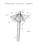
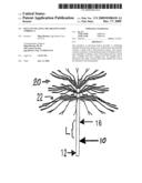
[0009]FIG. 1
[0010]Depicts the perspective and plan views of this improved invention.
[0011]FIG. 1a
[0012]Is an elevation of an umbrella according to this improved invention.
[0013]FIG. 1b
[0014]Is a top plan view of an umbrella according to this improved invention.
[0015]FIG. 1c
[0016]Is an upward perspective view of an umbrella according to this improved invention.
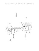
[0017]FIG. 2
[0018]Depicts perspective views of the trunk and canopy indicating different angles of the deployment of the canopy on the trunk.
[0019]FIG. 2a
[0020]Is a perspective view of a rectangular trunk.
[0021]FIG. 2b
[0022]Is a perspective view of the trunk and canopy including a spline.
[0023]FIG. 2c
[0024]Is a perspective view of a trunk having three canopies, the first canopy is deployed at an angle of 130 degrees. The second canopy is deployed at an angle of 110 degrees and the third canopy is deployed at an angle of 90 degrees with respect to the trunk.
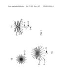
[0025]FIG. 3
[0026]Is a partial elevation view of the trunk and the splines including the deployment and retraction mechanisms of the umbrella.
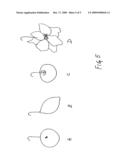
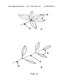
[0027]FIG. 4
[0028]Is a plan view of leaf designs for the garland.
[0029]FIG. 4a
[0030]Depicts a palmate leaf design.
[0031]FIG. 4b
[0032]Depicts a pinnate leaf design.
[0033]FIG. 4c
[0034]Depicts the garland which is comprised of a single center wire that has leaf compartments 4a, 4b wrapped around it completely to form the garland.
[0035]FIG. 5
[0036]Depicts several examples of attachable fruit and flowers made of plastic, with an attachable hook at the top, mimicking an ornament similar to those in the art of hanging ornaments.
DETAILED DESCRIPTION OF THE INVENTION
[0037]This improved invention is designed similar to most patio umbrellas, with one difference, it has multiple layered canopy system with individual splines that are wrapped with leaf designed garland. Referring to FIG. 1a an embodiment of the umbrella is shown that includes a trunk 10 and multiple canopies 20 circumferentially arranged around the trunk 10 and having splines 22. This improved umbrella, having multiple canopies, can be deployed and retracted in unison. Referring to FIGS. 1a and 1b, multiple canopies can provide an increase in the range of diameters achieved through deployment of canopies of different sizes, configurations and angles. In addition, multiple canopies can provide variety of shapes, greater umbrella stability during wind, and a thicker canopy for greater protection from the sun. The trunk 10 includes a proximal portion 16 and a distal portion 12 along a longitudinal axis L of the trunk. Referring to FIG. 2, the umbrella is shown that includes a trunk 10 and one or more canopies. FIG. 1a depicts the trunk 10 that is generally tubular and can contain a central lumen that can be used for carrying any wires or connectors suitable for operation of the umbrella. FIG. 2a depicts the infrastructure of a one canopy umbrella having splines 22 that forms an arc at an angle alpha 14 with respect to the longitudinal axis L of the trunk 10.
[0038]The angle alpha 14 can range from about 0 degrees in which a spline 22 is retracted and generally aligned with the longitudinal axis L of the trunk 10, to about 150 degrees or more, in which a spline 22 is moving upwardly to form into a branch of a natural tree with respect to the longitudinal axis L of the trunk 10. The hinged end 36 of a spline 22 is configured such that the distal end 38 of a spline 22 can assume a variety of positions along this are relative to the longitudinal axis L of a trunk 10. The various positions that multiple circumferentially disposed splines 22 can assume during deployment provide a total cone-shaped or frustum-shaped canopy 20 that undergoes an increase in surface area as the canopy is deployed. The mechanism to deploy and retract the canopy 20 will depend on the configuration of the canopy and the trunk 10. FIG. 2c depicts the infrastructure of an umbrella with three canopies 20A, 20B, and 20C. In the embodiment shown, the splines 22 in each canopy form an arc at a different angle alpha with respect to the longitudinal axis L of the trunk 10. In the embodiment shown in FIG. 2C, the angle alpha is 130 degrees, 110 degrees and 90 degrees in canopies 20A, 20B, 20C, respectively. Referring to FIG. 3, the canopy 20 is circumferentially arranged about the trunk 10. The canopy 20 includes a plurality of circumferentially disposed radial splines 22 whose free ends can extend outward from the trunk 10. In the embodiment illustrated in FIG. 3, the splines 22 are generally rod-like structures with a hinged end 36 attached directly to the trunk 10. The distal free end 38 of splines 22 is free to swing through an arc at an angle alpha 14 with respect to the longitudinal axis L of the trunk 10.
[0039]The angle alpha 14 can range from about 0 degree, in which splines 22 are retracted and generally aligned with the longitudinal axis L of the trunk 10, and about 90 degrees, in which splines 22 are fully deployed and lie in a plane perpendicular to the longitudinal axis L of the trunk 10. The hinged end 36 of a spline 22 is configured such that the distal end 38 of a spline 22 can assume a variety of positions along this are relative to the longitudinal axis L of the trunk 10. The trunk 10 and canopy 20 can be made from a variety of natural or synthetic materials having requisite strength and flexibility. The movement and position of the splines 22 with respect to the longitudinal axis L of the trunk 10 can be adjustably controlled by a variety of different means. The number and position of splines 22 as well as the manner in which hinged end 36 of splines is attached to a trunk can vary, and can be dependent at least in part on the mechanism by which the canopy 20 is deployed and retracted. The splines 22 can be attached to the trunk 10 by any number of methods. For example, in addition to the direct attachment mechanism shown in FIG. 1a, the embodiment shown in FIG. 3 demonstrates that the splines 22 can be attached to a central hub 28 that circumscribes the trunk 10. A slideable deployment/retraction collar 24 that circumscribes the trunk 10 is shown in FIG. 3. In this embodiment, the umbrella contains a slideable collar 24 that circumscribes the splines 22 at their distal ends 38 at a retractable position.
[0040]During deployment, the collar 24 can be adjustably moved toward the hinged end 36 of the splines 22. Movement of the collar 24 toward the hinged end 36 of the splines 22 causes the distal ends 38 of the splines to move through the arc and form a retracted position to any desired angle alpha with respect to the longitudinal axis L of the trunk 10. The collar 24 then engages the splines 22 during retraction and slides along the longitudinal axis L of the trunk 10 toward the distal ends 38 of the splines 22. As in FIG. 1a, the movement and position of the splines 22 with respect to the longitudinal axis L of the trunk 10 can be precisely controlled by the slideable deployment/retraction collar 24. Splines 22 can be made from a rigid material or a material that allows, for example, a bowed spline as shown in FIG. 1 For example, splines 22 can be constructed using a variety of natural and/or synthetic materials known in the art.
[0041]The length and splines 22 can vary and will depend on the configuration of the canopy, materials used to make the splines and the mechanism of deployment and retraction. FIG. 4 mimics the shape and form of leaves in nature and can be customized according to the intended use and the user's specification. FIG. 4c shows a continuous strand of leaf compartments that are made in the form of garland similar to any garland currently in the art. Various leaf shapes such as in FIG. 4 can mimic leaves from trees like, but not limited to the Apple, Orange, Lemon, Magnolia, Peach, Cherry, Sycamore, or Yellowwood trees, among others. FIGS. 5a, 5b, 5c, and 5d are optional attachments for the umbrella of this improved invention, which are comprised of synthetic material. They come in a variety of forms not limited to lemons, apples, oranges, and magnolia flowers.
User Contributions:
comments("1"); ?> comment_form("1"); ?>Inventors list |
Agents list |
Assignees list |
List by place |
Classification tree browser |
Top 100 Inventors |
Top 100 Agents |
Top 100 Assignees |
Usenet FAQ Index |
Documents |
Other FAQs |
User Contributions:
Comment about this patent or add new information about this topic:
| People who visited this patent also read: | |
| Patent application number | Title |
|---|---|
| 20160146619 | NAVIGATION ROUTE COOPERATION NAVIGATION SYSTEM AND METHOD OF CONTROLLING THE SAME |
| 20160146618 | METHOD TO GAIN DRIVER'S ATTENTION FOR AUTONOMOUS VEHICLE |
| 20160146617 | METHOD AND APPARATUS FOR DETERMINING TRAJECTORY PATHS ON A ROAD NETWORK |
| 20160146616 | VEHICLE POSITIONING BY MAP MATCHING AS FEEDBACK FOR INS/GPS NAVIGATION SYSTEM DURING GPS SIGNAL LOSS |
| 20160146615 | Systems and Methods for Driver and Vehicle Tracking |
Images included with this patent application:
 |  |
 |  |
 |  |
| Similar patent applications: | |
| Date | Title |
|---|---|
| 2012-11-01 | Cushioning device for umbrella |
| 2013-01-17 | Foldable tentaanm jin; ki hoaaci rongshen new cityaaco cnaagp jin; ki ho rongshen new city cn |
| 2009-05-14 | Rain protection umbrella |
| 2009-08-20 | Control device for umbrella |
| 2010-05-13 | Rain protection umbrella |
| New patent applications in this class: | |
| Date | Title |
|---|---|
| 2016-07-07 | Foldable parasol |
| 2016-06-30 | Novel lighting umbrella |
| 2016-04-21 | Multi-purpose floating umbrella |
| 2016-04-07 | Outdoor umbrella with built-in electro control panel |
| 2015-12-31 | High capacity solar charging umbrella |
| New patent applications from these inventors: | |
| Date | Title |
|---|---|
| 2009-12-17 | Non-glue based moistorizing device |
| Top Inventors for class "Tent, canopy, umbrella, or cane" | |
| Rank | Inventor's name |
|---|---|
| 1 | Oliver Joen-An Ma |
| 2 | Mark C. Carter |
| 3 | Wanda Ying Li |
| 4 | Wanda Ying Li |
| 5 | Kendyl A. Roman |