Patent application title: HORTICULTURAL APPLICATOR DEVICE
Inventors:
Timothy Dean Heckler (Perth, AU)
Adam Matthew Wake (Perth, AU)
IPC8 Class: AA01M2104FI
USPC Class:
47 15
Class name: Plant husbandry plant surface contact material applicator
Publication date: 2009-11-26
Patent application number: 20090288338
Inventors list |
Agents list |
Assignees list |
List by place |
Classification tree browser |
Top 100 Inventors |
Top 100 Agents |
Top 100 Assignees |
Usenet FAQ Index |
Documents |
Other FAQs |
Patent application title: HORTICULTURAL APPLICATOR DEVICE
Inventors:
Timothy Dean Heckler
Adam Matthew Wake
Agents:
DAVID A. GUERRA;INTERNATIONAL PATENT GROUP, LLC
Assignees:
Origin: CALGARY, AB CA
IPC8 Class: AA01M2104FI
USPC Class:
47 15
Patent application number: 20090288338
Abstract:
A horticultural applicator (10) device comprising a raft (12) having a
means for applying a substance to plants (14) and a means to drag the
raft (22). The raft (12) is dragged over the top of the plants and the
means for applying the substance (14) mounted to the raft (12) applies
the substance onto said plants.Claims:
1-13. (canceled)
14: A horticultural applicator system for delivering substances such as herbicides, pesticides, and fertilizers to areas that are difficult to access, said horticultural applicator system comprising:a raft being an open top vessel;a means to drag said raft, wherein said raft is dragged over the top of plants; anda means for applying a substance mountable to said raft, said means applies said substance onto the plants.
15: The horticultural applicator system as set forth in claim 14, wherein said raft comprising a lower surface, and first and second side surfaces extending upwardly and outwardly from said lower surface at opposite ends thereof, and said means to drag said raft moves the raft in the direction of either said first or second side surface.
16: The horticultural applicator system as set forth in claim 15, wherein said first and second side surfaces are generally planar and extend from said lower surface at an angle of less than ninety degrees.
17: The horticultural applicator system as set forth in claim 16, wherein said raft includes first and second end surfaces extending generally perpendicular from opposite ends of said lower surface between said first and second side surfaces.
18: The horticultural applicator system as set forth in claim 17, wherein said means for dragging said raft comprises a cable secured to said raft.
19: The horticultural applicator system as set forth in claim 18, wherein said means for applying the substance comprising a boom mountable to said raft.
20: The horticultural applicator system as set forth in claim 19, wherein said boom is pivotable between a position in which it lies beyond the extents of said raft adjacent said first side surface thereof and a position in which it lies beyond the extents of said raft adjacent said second side surface thereof.
21: The horticultural applicator system as set forth in claim 20, wherein said boom is connected to at least one arm member, said arm member being pivotally mounted to an elongate member extending between said first and second end surfaces of said raft.
22: The horticultural applicator system as set forth in claim 18, wherein said means for applying the substances is provided on said lower surface of said raft.
23: The horticultural applicator system as set forth in claim 22, wherein said means for applying the substance is provided within a recessed portion on said lower surface of said raft, said recessed portion extending between said first end surface of said raft and said second end surface of said raft.
24: The horticultural applicator system as set forth in claim 23, wherein said recessed portion is generally semi-circular in cross section.
25: The horticultural applicator system as set forth in claim 18, wherein said means for applying the substance comprises a plurality of spray nozzles.
26: The horticultural applicator system as set forth in claim 18, wherein said means for applying the substance comprises a plurality of wick applicators.
27: A horticultural applicator system comprising:a raft being raft comprising a lower surface, first and second side surfaces extending upwardly and outwardly from said lower surface at opposite ends thereof, and first and second end surfaces extending generally perpendicular from opposite ends of said lower surface between said first and second side surfaces;a first cable attached to said first side surface, said first cable being adapted to drag said raft over a surface;a second cable attached to said second side surface, said second cable being adapted to drag said raft over the surface in a direction opposite of said first cable;a boom mountable to said raft, said boom being adapted to apply a substance onto plants traveling below said lower surface of said raft; anda flexible feed conduit in fluid communication with said boom.
28: The horticultural applicator system as set forth in claim 27, wherein said first and second side surfaces are generally planar and extend from said lower surface at an angle of less than ninety degrees.
29: The horticultural applicator system as set forth in claim 28, wherein said boom is pivotable between a position in which it lies beyond the extents of said raft adjacent said first side surface thereof and a position in which it lies beyond the extents of said raft adjacent said second side surface thereof.
30: The horticultural applicator system as set forth in claim 29, wherein said boom is connected to at least two arm members, said arm members being pivotally mounted to an elongate member extending between said first and second end surfaces of said raft.
31: The horticultural applicator system as set forth in claim 27, wherein said means for applying the substances is provided on said lower surface of said raft.
32: The horticultural applicator system as set forth in claim 31, wherein said means for applying the substance is provided within a recessed portion on said lower surface of said raft, said recessed portion extending between said first end surface of said raft and said second end surface of said raft, and wherein said recessed portion is generally semi-circular in cross section.
33: A horticultural applicator system comprising:a raft being raft comprising a lower surface, first and second side surfaces extending upwardly and outwardly from said lower surface at opposite ends thereof, and first and second end surfaces extending generally perpendicular from opposite ends of said lower surface between said first and second side surfaces, said first and second side surfaces are generally planar and extend from said lower surface at an angle of less than ninety degrees;a first cable attached to said first side surface, said first cable being adapted to drag said raft over a surface;a second cable attached to said second side surface, said second cable being adapted to drag said raft over the surface in a direction opposite of said first cable;an elongate member extending between said first and second end surfaces of said raft;at least two arm members pivotally mountable to said elongate member;a boom attachable to said two arm members allowing for said boom to pivotally travel between a position in which it lies beyond the extents of said raft adjacent said first side surface thereof and a position in which it lies beyond the extents of said raft adjacent said second side surface thereof, said boom being adapted to apply a substance onto plants traveling below said lower surface of said raft; anda flexible feed conduit in fluid communication with said boom.
Description:
FIELD OF THE INVENTION
[0001]The present invention relates a horticultural applicator device for carrying a spray boom or similar device used to deliver substances such as herbicides to areas that are difficult to access.
BACKGROUND OF THE INVENTION
[0002]It is often desired to apply herbicides to control weeds such as typha that grow in seasonally inundated lakes. Spraying such weeds is a difficult task due to problems gaining access to the weed. The known method requires wading through the area and manually spraying the weed. This method is extremely time consuming and strenuous for the person spraying. It is also difficult to achieve an effective result and hazardous to the operator due to venomous or otherwise dangerous fauna that live in such areas.
[0003]It is known to use boom sprays or other application means in many areas of agriculture, horticulture and natural area management. Such application means are generally mounted on, or towed by a vehicle and allow even spraying over a wide area. The use of boom sprays in areas such as mentioned above however is impractical, as it is not possible to gain access to these areas with a vehicle. Other devices such as a wiping wick applicator system can also be used but still have the same access problem.
[0004]The present invention attempts to overcome at least in part the aforementioned problems of spraying plants in difficult to access areas.
SUMMARY OF THE INVENTION
[0005]In accordance with one aspect of the present invention there is provided a horticultural applicator device comprising a raft having a means for applying a substance to plants and a means to drag the raft, wherein the raft is dragged over the top of the plants and the means for applying the substance mounted to the raft applies the substance onto said plants.
BRIEF DESCRIPTION OF THE DRAWINGS
[0006]The present invention will now be described, by way of example, with reference to the accompanying drawings, in which:
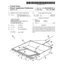
[0007]FIG. 1 is an upper perspective view of a horticultural applicator in accordance with the present invention;
[0008]FIG. 2 is a side cross sectional view of the horticultural applicator of FIG. 1;
[0009]FIG. 3 is an upper perspective of an alternative embodiment of a horticultural applicator in accordance with the present invention; and
[0010]FIG. 4 is a side cross sectional view of the horticultural applicator of FIG. 3.
DESCRIPTION OF THE INVENTION
[0011]Referring to the Figures, there is shown a horticultural applicator device 10 including a raft 12 and a means for applying a substance, such as a herbicide, to plants.
[0012]The raft 12 comprises an open top vessel having a lower surface 16, first and second opposed side surfaces 18 and 19 and first and second opposed end surfaces 20 and 21. The lower surface 16 is generally planar. The first and second opposed end surfaces 20 and 21 extend generally upwardly from and perpendicular to the lower surface 16 at opposite ends thereof. The first and second side surfaces 18 and 19 extend upwardly from opposite sides of the lower surface 16 at an angle less than 90 degrees. The angle of the first and second side surfaces 18 and 19 to the lower surface 16 is such that, when the raft 12 is dragged along in the direction of one of the side surfaces 18, the angle of the side surfaces 18 and 19 allow the raft 12 to slide up and onto plants to be sprayed.
[0013]The raft 12 includes a means for dragging the raft 12 in the direction of either of the first or second side surfaces 18 and 19. The means for dragging the raft 12 comprises a first cable 22 attached to the first side surface 18 and a second cable 24 attached to the second side surface 19.
[0014]In the embodiment shown in FIGS. 1 and 2, the means for applying a substance comprises a boom 14 having a plurality of spray nozzles 15 located thereon. The boom 14 is pivotally mounted about a central elongate member 26 on the raft 12. The elongate member 26 extends across the raft 12 from the first end surface 20 to the second end surface 21. The boom 14 is mounted parallel to the elongate member 26 at the end of arm members 28 arranged to pivot about the elongate member 26. The length of the arm members 28 is such that the boom 14 can be pivoted between a position in which it lies beyond the extents of the raft 12 adjacent the first side surface 18 and a position in which it lies beyond the extents of the raft 12 adjacent the second side surface 19. A flexible feed conduit 30 is provided to supply the fluid to be sprayed to the nozzles 15 on the boom 14.
[0015]In the embodiment shown, the boom 14 is arranged to spray a fluid, such as herbicide, onto the plants. In an alternative embodiment, the means for applying a substance to the plants may comprise a boom having wick style applicators in which the wicks contact the plants and deliver the herbicide. The wick applicators may alternatively be mounted directly to the raft 12, without the use of the boom 14. It is also envisaged that other substances may be applied. For example, it may be desired to apply pesticides or fertilisers to the plants. The means of applying the substance, such as spray jets, wick or other suitable means, will be selected based on the particular application.
[0016]The embodiment shown in FIGS. 3 and 4, the means for applying a substance comprises a plurality of spray nozzles 15 located on the lower surface 16 of the raft 12. The lower surface 16 is provided with a recessed portion 40 extending from the first end surface 20 to the second end surface 21 in which the spray nozzles 15 are located. The spray nozzles 15 apply the sprayed substance to the area below the recessed portion 40. The recessed portion 40 is generally semi-circular in cross section having the nozzles 15 mounted along the length thereof. A flexible feed conduit 30 connected to the nozzles 15 from within the raft 12 supplies the substance to be sprayed to the nozzles 15.
[0017]In use, when using the applicator device of FIGS. 1 and 2, the raft 12 is positioned adjacent an area to be sprayed with the first cable 22 extending across the area to be sprayed and the boom 14 positioned adjacent the second side surface 18 (as shown in FIG. 1). A force is applied to the first cable 22 by suitable means, such as a winch, to drag the raft 12 across the plants to be sprayed. The angled first side surface 18 allows the raft to pass on top of the plants, bending the plants over. The nozzles 15 spray the desired fluid (for example herbicide) onto the plants passing out from under the second side surface 19.
[0018]The lower surface 16 and first and second side surfaces 18 and 19 of the raft 12 are constructed from a material having a low coefficient of friction such that the raft 12 can be easily dragged across these surfaces. Also the raft 12 is constructed such that the weight of the raft 12 allows the raft 12 to be dragged over top of the plant to be sprayed in a manner that bends the plant but allows the plant to return to an upright position. For example, with weeds such as typha, it is preferred that the weight be such that approximately the top one third of the plant is bent over. The bending over of the plant allows more efficient spraying as the fluid is sprayed onto the side surface of the plant, at the optimal distance from the boom 14, resulting in maximum coverage and minimal pressure and flow. The `bending over` of the canopy minimises over-spraying and the off-target damages to native understorey this would cause.
[0019]When the raft 12 reaches the end of the area to be sprayed, it may be returned to the starting position by applying a force to the second cable 24, where it can be moved across to spray an adjacent area. Alternatively, the boom spray 14 may be pivoted about the elongate member 26 so it is adjacent the first side surface 18, the raft 12 moved across by the width of the raft 12 and then dragged back in the direction of the second side surface 19 spraying along the way.
[0020]The use of the embodiment shown in FIGS. 3 and 4 will be the same but will eliminate the need to pivot the boom 14 when changing the direction of movement of the raft 12.
[0021]Modifications and variations as would be apparent to a skilled addressee are deemed to be within the scope of the present invention.
User Contributions:
comments("1"); ?> comment_form("1"); ?>Inventors list |
Agents list |
Assignees list |
List by place |
Classification tree browser |
Top 100 Inventors |
Top 100 Agents |
Top 100 Assignees |
Usenet FAQ Index |
Documents |
Other FAQs |
User Contributions:
Comment about this patent or add new information about this topic:
Images included with this patent application:
 |  |
 |
| Similar patent applications: | |
| Date | Title |
|---|---|
| 2009-04-16 | Chemical application line |
| 2011-06-16 | Horticultural display |
| 2012-10-25 | Sprout cultivation device |
| 2013-11-21 | Method for producing an ornamental horticultural pot |
| 2013-12-12 | Vertical agricultural structure |
| New patent applications in this class: | |
| Date | Title |
|---|---|
| 2019-05-16 | Fertilizer allocation system and fertilizer allocation method |
| 2016-06-09 | Vegetation cut and application method and apparatus |
| 2016-03-03 | Mobile tree canopy treatment system |
| 2016-02-25 | Movable heat applicator for providing thermotherapy to trees |
| 2016-02-18 | Dispenser for dispensing foam such as foam herbicides |
| Top Inventors for class "Plant husbandry" | |
| Rank | Inventor's name |
|---|---|
| 1 | Donald E. Weder |
| 2 | Frank M. Stewart |
| 3 | Bruce G. Kania |
| 4 | Michael R. Klemme |
| 5 | David S. Mackenzie |