Patent application title: ESTABLISHING THE INTEGRITY OF CONTAINER CONTENTS
Inventors:
William Eugene Hodge (Lumby, CA)
IPC8 Class: AB65D8500FI
USPC Class:
2064591
Class name: Special receptacle or package with indicator (i.e., variable information exhibiting means)
Publication date: 2009-11-19
Patent application number: 20090283434
Inventors list |
Agents list |
Assignees list |
List by place |
Classification tree browser |
Top 100 Inventors |
Top 100 Agents |
Top 100 Assignees |
Usenet FAQ Index |
Documents |
Other FAQs |
Patent application title: ESTABLISHING THE INTEGRITY OF CONTAINER CONTENTS
Inventors:
William Eugene Hodge
Agents:
WILLIAM E. HODGE
Assignees:
Origin: LUMBY, BC CA
IPC8 Class: AB65D8500FI
USPC Class:
2064591
Patent application number: 20090283434
Abstract:
A method and associated apparatus are given for a novel way to overcome
the difficulty of achieving absolutely certainty that the contents of a
cargo container have not been accessed between the time it is packed and
sealed at its point of origin and the time it is reopened at its
destination. The concept is rather than to try to make the container
impregnable, is to make certain that if the integrity of a container is
violated, then than fact will be recorded without fail. The method
consists of placing the cargo inside a secure enveloping structure, the
physical continuity of which cannot be cut, or interrupted however
briefly, without authorities being alerted. To achieve this the
enveloping structure is made of semiconducting material. Immediately
prior to sealing the contents at the point of origin a monitoring device
housed inside the envelope is switched on. This device will monitor and
record the temperature compensated electrical conductivity of the
enveloping structure on a frequent and continual basis for the entire
period of transit, the output of which will alert authorities of any
interruption of continuity. The semiconductive material from which the
secure envelope is made may be rigid and/or transparent. The envelope may
be in the shape and size proportions of a typical metal freight container
to facilitate its transportation to its destination in one of these
common carriers.Claims:
1. A method to ensure that the enveloping structure of a secured container
cannot be breached without such infringement being detected and being
automatically recorded as it happens.
2. A container whose enveloping structure consists of an integrated semiconductive material which incorporates suitably deployed electrodes and insulators and a monitoring device capable of recording the time history of temperature compensated conductivity of the envelope.
3. A container whose enveloping structure consists of an integrated semiconductive transparent material which incorporates suitably deployed electrodes and insulators and a monitoring device capable of recording the time history of temperature compensated conductivity of the envelope.
Description:
BACKGROUND OF INVENTION
[0001]1. Field of Invention
[0002]The method and apparatus described herein are intended to provide the means to establish with complete confidence that the contents of a container have not been accessed or tampered with, or new objects added, between the time the container was packed, locked, and dispatched from its point of origin until a subsequent time when an authorised person or mechanism unlocks and opens it at the receiving end.
[0003]One particular potential application of this novel approach is the security of the cargo within metal cargo containers, in which case such a tamper-proof container would be placed inside one of those standard, or common, metal units.
[0004]2. Description of Related Art
[0005]Current practice in establishing the integrity of a typical cargo container and its contents, as far as the inventor is aware, does not have available to it a simple and reliable way of solving the problem of assuring a container's enveloping structure has not been partially opened temporarily and then that opening closed and evidence of the infringement disguised or hidden from detection in some way.
[0006]3. Problems with Current Practice
[0007]The fundamental difficulty in finding a solution to this problem, other than what is disclosed herein, is that the material from which the typical freight container is made is steel, which material, because of its physical properties, is amenable to cut-and-paste as is readily apparent in the automobile repair industry. In consequence, it is difficult to know that a typical cargo container has not been entered between the time it is dispatched and the time of its arrival at its destination.
SUMMARY OF THE INVENTION
[0008]1. Disclosure of the Invention
[0009]The novel method presented below is based on fabricating a container from a semiconducting material so that by then monitoring the conductivity of this enclosing envelope, any breach of the container sides may be established with certainty and that fact recorded in real time. Consequently, attempting to hide physical evidence of a security breach, however well disguised the repair may be, will be to no avail.
[0010]The intent is to ensure that any tampering with the container cannot go unobserved. Because of the structural characteristics of the container advocated herein it is anticipated that for ground and sea transportation this container may advantageously be shipped inside a standard steel cargo container.
[0011]The invention requires two novel pieces of apparatus. One is a container whose sides and door(s) are made from interconnected panels of a semiconducting material. The other is a monitoring system to measure and record the electrical conductivity of the overall container.
[0012]2. Description of Semiconductive Container
[0013]The semiconducting material from which the container is build could be simply a plastic sheet in which is imbedded wire mesh, that is, a conducting mesh fused between two outer sheets of plastic. A more refined version of this could be a randomized interconnected patterns formed of transparent conductive film attached to one sheet of plastic and then covered by another sheet of plastic, and the three layers then bonded into a single coherent sheet. The edges of these side wall component would be joined in such a manner as to ensure continuity of all or some of the conductivity of each edge, so that the entire container would behave as a single semiconductive continuum. Alternatively, an intermittently conductive adhesive bonding agent could be used to further randomize the interconnectedness of the conductive mesh or film forming the panels.
[0014]On the inside of the container two separated electrodes of opposite polarity would be attached to the conductive mesh or film. Advantageously, these electrodes could be positioned on either side of the door as shown in the drawings. The intent here is to be able to introduce an electrical potential difference between the electrodes thereby permitting the measurement of the resistance of the entire system. The idea being that any disturbance to the semiconductor's capacity to carry a current would show up in a change of electrical resistance of the container.
[0015]In the case where a container was open at the top, as in a drawer, a flexible insulated wire mesh could be draped over the top opening and then attached to the semiconducting elements in those walls. The circuitry shown in FIG. 1 would be more suitable in this particular instance.
[0016]The option also exists to deal with each side panel separately, rather than dealing with a single overall semiconducting circuit.
[0017]Alternatively, to avoid the use of a separate semiconductive container, a composite membrane could be applied to the inside of a typical metal container. This membrane would consist of an outer insulating layer in contact with the metal surfaces of the container, then a semiconducting film followed by a second insulating layer. An inner protective coating would be needed on the cargo side of the membrane. Frequent inspections of this membrane would be necessary to ensure it was not ruptured by torsional distortion of the metal structure during transportation.
[0018]Insulation of the semiconductive shield from necessary hardware such as hinges and locks is required to prevent these relatively highly conductive objects from introducing outside influences or diminishing sensitivity of the overall circuit.
[0019]3. Description of Monitoring Device
[0020]The monitoring system would consist of the following off-the-shelf items, the arrangement and purpose of which is believed novel. This monitor would be housed inside the container. [0021]Electrical power source. [0022]Means of measuring electrical resistance/conductivity. [0023]Thermistor or other temperature measuring device. [0024]Data-logger, or a similar means of recording on an ongoing basis throughout the transit period, the values of conductivity and temperature of the semiconductor circuit, and possibly other environmental parameters. [0025]Software, or custom designed integrated circuit, to normalize the value of conductivity for changes in temperature, and to set an alarm signal if the normalized conductivity value exceeded a sensitivity range. [0026]Means of transmitting and/or broadcasting the data from the monitor.
BRIEF DESCRIPTION OF THE DRAWINGS
[0027]Aspects of the invention are illustrated, merely by way of example, in the accompanying drawings show just two of the many possible circuits which could be constructed by the way in which nonconductive insulation strips are deployed to prevent a simple short-circuiting of the potential. For clarity neither the monitoring device nor the lock and hinges are shown.
LIST OF REFERENCE NUMERALS
[0028]10 container [0029]11 container with doors open [0030]12 container with doors closed [0031]21 door [0032]22 upright closing edge of door [0033]31 semiconductive panel [0034]32 electrode [0035]33 nonconductive strip
DESCRIPTION OF PREFERRED EMBODIMENTS
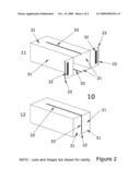
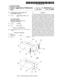
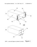
[0036]FIG. 1 shows a container 10 where in the upper sketch 11 its doors 21 are open and in the lower sketch 12 its doors are closed. All sides or walls including the doors of the container are semiconducting panels 31. A pair of electrodes 32 are imbedded at some advantageous positions within this semiconductive envelope. In the configuration shown here the electrical continuity of this enveloping structure is physically interrupted by nonconductive strips 33 on the closing edges of the doors.
[0037]FIG. 2 shows one alternative deployment of nonconductive strips 33 where the discontinuity of electrical conductivity is along part of the upper and lower panels and on the upright closing edge of the doors 22.
Operation of the Invention
[0038]Prior to leaving the factory for the first time the container would be subjected to a calibration process which would include the determination of the electrical conductivity-to-temperature relationship for that particular unit for the record.
[0039]In the case of ground or sea traffic the semiconductive container would likely be placed inside a typical metal freight container such as those towed by trucks or carried by railways. The cargo would then be placed inside the semiconductive container in the normal fashion.
[0040]Prior to closing and locking the doors, the monitoring system would be activated. Monitoring the conductivity of the secured container at a high frequency rate, say once every second (1 Hz), would ensure that any breach of the semiconductive envelope would be detected. If this envelope remained intact, indicated by an unchanged conductivity (normalized for temperature), it would be known that the integrity of the cargo and the container had not been violated.
[0041]Obviously, it is possible to feed the data from the monitoring system by modem (or similar technology) to custom or port authorities ahead of the arrival of the cargo into their jurisdiction.
CROSS-REFERENCE TO RELATED APPLICATIONS
[0042]This application claims priority under 35 U.S.C 119(e) to U.S. Provisional Patent application No. 61/071,799 filed May 19, 2008, the disclosure of which is incorporated herein by reference.
User Contributions:
comments("1"); ?> comment_form("1"); ?>Inventors list |
Agents list |
Assignees list |
List by place |
Classification tree browser |
Top 100 Inventors |
Top 100 Agents |
Top 100 Assignees |
Usenet FAQ Index |
Documents |
Other FAQs |
User Contributions:
Comment about this patent or add new information about this topic:
Images included with this patent application:
 |  |
 |
| Similar patent applications: | |
| Date | Title |
|---|---|
| 2013-07-11 | Closing device for a container and container comprising said closing device |
| 2013-06-06 | Nestable collapsible containers |
| 2010-02-25 | Eating utensil contaminant shield |
| 2010-12-09 | Eating utensil contaminant shield |
| 2013-07-11 | Systems, devices, and methods for increasing consumer access to first aid supplies |
| New patent applications in this class: | |
| Date | Title |
|---|---|
| 2019-05-16 | Carton with tab |
| 2018-01-25 | Apparatus and method for monitoring cargo conditions |
| 2016-09-01 | Product and package with a photosensitive use-evident feature |
| 2016-09-01 | Reservoir |
| 2016-07-07 | Enclosable container system and sealing indicator |
| New patent applications from these inventors: | |
| Date | Title |
|---|---|
| 2011-07-28 | Definition of universal constants by positive integers |
| 2009-10-22 | Pre-loading of building sites over compressible strata |
| Top Inventors for class "Special receptacle or package" | |
| Rank | Inventor's name |
|---|---|
| 1 | Donald E. Weder |
| 2 | Brett R. Glass |
| 3 | Daniel Lee Bizzell |
| 4 | Andrea Biondi |
| 5 | Nicole E. Glass |