Patent application title: Device for rapidly mounting a mechanical assembly on a support
Inventors:
Xavier Bibes (Pessac, FR)
Assignees:
THALES
IPC8 Class: AB65D1922FI
USPC Class:
24834606
Class name: Supporting base including attachment or holder for article base allows attachment or holder to adjust position
Publication date: 2009-11-05
Patent application number: 20090272868
Inventors list |
Agents list |
Assignees list |
List by place |
Classification tree browser |
Top 100 Inventors |
Top 100 Agents |
Top 100 Assignees |
Usenet FAQ Index |
Documents |
Other FAQs |
Patent application title: Device for rapidly mounting a mechanical assembly on a support
Inventors:
Xavier BIBES
Agents:
LOWE HAUPTMAN HAM & BERNER, LLP
Assignees:
THALES
Origin: ALEXANDRIA, VA US
IPC8 Class: AB65D1922FI
USPC Class:
24834606
Patent application number: 20090272868
Abstract:
The present invention relates to a device for rapidly mounting a
mechanical assembly on a support. The device comprises at least one
mounting module (3) having a male part (22) mechanically fixed to the
assembly (1) and a female part (21) mechanically fixed to the support
(2), the male part (22) fitting into the female part (21), the female
part having a thrust system (25, 26) locking the male part (22) against a
wall of the female part (21) once the male part has been fitted
thereinto. The invention relates notably to the mounting of a tool on a
support, for example a vibrating support, notably for a testing station.Claims:
1. A device for mounting a mechanical assembly on a support, wherein the
device comprises at least one mounting module having a male part
mechanically fixed to the assembly and a female part mechanically fixed
to the support, the male part fitting into the female part, the female
part having a thrust system locking the male part against a wall of the
female part once the male part has been fitted thereinto, the male part
having a projecting portion penetrating into a modified side wall of the
female part, the projecting portion being locked into the modified side
wall under the effect of the thrust of the system.
2. The device as claimed in claim 1, wherein the female part has a side wall with a conical internal form, the male part having a conical projecting portion which locks into the conical internal wall under the effect of the thrust of the system.
3. The device as claimed in claim 1, wherein the thrust system is a cylinder.
4. The device as claimed in claim 3, wherein the cylinder is double-acting.
5. The device as claimed in claim 1, which has a circuit (4) for pressurizing the cylinder of a module.
6 The device as claimed in claim 1, wherein the cylinder (25, 26) is provided on the wall opposite the conical internal wall.
7. The device as claimed in claim 1, wherein the cylinder is pneumatic.
8. The device as claimed in claim 1, wherein the female part (21) is mounted on the support by means of a screw.
9. The device as claimed in claim 1, wherein the male part (22) is mounted on the mechanical assembly by means of a screw.
10. The device as claimed in claim 1, wherein the female part has an upper wall having an opening for the male part to pass through.
11. The device as claimed in claim 1, wherein the support is a vibrating table.
12. The device as claimed in claim 1, wherein the mechanical assembly is a tool.
Description:
[0001]The present invention relates to a device for rapidly mounting a
mechanical assembly on a support. It relates notably to the mounting of a
tool on a support, for example a vibrating support, notably for a testing
station.
[0002]In order to mount notably tools, conventional mounting techniques use screws requiring a considerable intervention time under lengthy, tiresome and difficult accessibility conditions. Indeed, it is generally necessary to remove the equipment from its support, to bend down, or even to get into the equipment, in order to unscrew numerous screws that are difficult to access between the uprights holding the equipment. The conditions may be even more complicated when the equipment consists, for example, of vibrating machines or when there is complementary equipment such as notably ventilation or cooling circuits.
[0003]It is an object of the invention notably to alleviate the abovementioned drawbacks by dispensing with the screw mounting. To this effect, the subject of the invention is a device for mounting a mechanical assembly on a support comprising at least one mounting module having a male part mechanically fixed to the assembly and a female part mechanically fixed to the support, the male part fitting into the female part, the female part having a thrust system locking the male part against a wall of the female part once the male part has been fitted thereinto.
[0004]Advantageously, the male part may have a projecting portion penetrating into the modified side wall of the female part, the projecting portion being locked into the modified side wall under the effect of the thrust of the system.
[0005]The female part has, for example, a side wall with a conical internal form, the male part then having a conical portion which locks into the conical internal wall under the effect of the thrust of the system.
[0006]Advantageously, the thrust system may be a cylinder, for example a double-acting cylinder.
[0007]The device has, for example, a circuit for pressurizing the cylinder of a mounting module.
[0008]The support is, for example, a vibrating table. The mechanical assembly is, for example, a tool.
[0009]Further features and advantages of the invention will become apparent by way of the description which follows with reference to the appended drawings, in which:
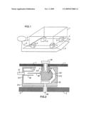
[0010]FIG. 1 shows a simplified overall view of a tool mounted on a support by a device according to the invention; and
[0011]FIG. 2 shows an embodiment of a mounting module, a constituent part of a device according to the invention.
[0012]FIG. 1 shows, by way of an overall view, a tool 1 mounted on a support 2 by a device 3, 4 according to the invention. The device according to the invention has a set of mounting modules 3 connected, for example, to a supply circuit 4, for example under pneumatic or hydraulic pressure.
[0013]FIG. 2 shows a schematic view of an exemplary embodiment of a mounting module 3.
[0014]The mounting module has a female part 21 and a male part 22. The female part 21 is mounted on the support 2. This part 21 is, for example, mounted on the support 2 by way of a screw 23.
[0015]The male part is mounted on the tool itself, for example by means of a mounting screw 24. The male part 22 and the female part 21 may be fitted together without play.
[0016]The female part 21 has, for example, a base 210 in contact with the support 2, having, for example, at least one hole for the mounting screw 23 to pass through, side walls 211, 212 and optionally an upper wall 213, thus forming a box. An opening 214 is provided for the male part 22 to pass through. In the example of FIG. 2 the male part has a side wall 212 having a conical internal form. This conical internal form is designed to receive a portion 221 of the male part 22 having a conical projecting form.
[0017]The female part 21 has, moreover, a cylinder 25, 26 mounted, for example, on the side wall 211 opposite the side wall 212 having a conical internal form. Once the male part 22 is enclosed within the female part 21, the piston 26 of the cylinder pushes the male part 22 such that its conical portion bears against the conical internal wall 212, bringing about the mounting of the male part in the female part and therefore the mounting of the tool 1 on the support 2. This mounting is brought about by the pressurization of the cylinder 25, 26 by the supply circuit 4. The cylinder may notably be pneumatic or hydraulic. To this end, an adaptor 27 connects the cylinder to the supply circuit 4.
[0018]A mounting device according to the invention has as many mounting modules 3 as are required for the size of the tool. Once the male parts are fitted into the female parts, mounting is brought about by the activation of the cylinders 25, 26 provided within the female parts 21. If the cylinders are of the pneumatic type, they can be supplied by a compressed air circuit 4 which is generally available in factories.
[0019]The support 2 may be a vibrating table, depending on the equipment tested, for example.
[0020]As FIGS. 1 and 2 show, the invention allows tools to be mounted while dispensing with the conventional screw mounting which requires a considerable intervention time under lengthy, tiresome and difficult accessibility conditions, since it may notably be necessary to remove some equipment from its support, to bend down, or even to get into the vibrating machine in order to unscrew numerous screws that are difficult to access between the uprights holding the equipment and the ventilation ducts.
[0021]Advantageously, the invention allows any type of tool to be mounted, without play and in a few seconds, in an environment that is very restricting in terms of vibration and temperature. It can be attached to existing tools by the addition of one or more male parts 22 having a complementary conical internal form 221 and attached for example permanently to the tool, in place of each of the former mounting screws.
[0022]On the support side 2 or on the vibrating table side, the female part 21 includes, for example, the cylinder 25, 26 supplied, for example, with compressed air from the factory network if it is pneumatic. The female part 21 is thermally insulated in order to reduce the impact of thermal shocks on the reliability and efficiency of the cylinder, the pressing capacity of which is chosen depending on the maximum density of the equipment, on the measurements between the former mounting screws, on the level of vibration to be transmitted between the table and the tool 1, and on the ambient temperature extremes.
[0023]The conical form and complementary conical form 212, 221 are chosen to allow multidirectional locking and thus to bear vibrations and forces in all directions without play and without absorbing the vibrations and forces to be transmitted.
[0024]The preload required at the cylinders takes account of the maximum forces encountered in order that the form and the complementary form 212, 221 never come apart during tests.
[0025]The angle of the cone is likewise chosen in order to prevent jamming between the form and the complementary form during disassembly.
[0026]The cylinder is chosen for example to be double-acting in order for the cone to be easily removed from the complementary form during disassembly of the tool/equipment assembly, without the worker intervening in the chamber.
[0027]The invention has variant embodiments, such as: [0028]all conical forms and complementary forms can be replaced notably by pyramidal forms, forms with cut-off corners, with spikes or with cams, provided they are chosen wisely; [0029]systems based on toggle clips, a vacuum pump or an inflatable metal balloon, for example, can replace the cylinders 25, 26 notably if compressed air is not readily accessible. Toggle clips are, however, less advantageous, since the worker has to intervene for longer than with cylinders. Vacuum pumps may discharge the nitrogen from the chamber, and inflatable metal balloons are more difficult to dimension and have a higher leakage rate.
[0030]The invention has very many advantages. It allows the creation of a standard for rapid mounting (replacing a screw with a system), the use of pre-existing interfaces, rapid prepositioning techniques, rapid mounting, the use of factory compressed air, the transmission of vibrations without damping and without attachment play (very damaging in a vibrating environment). Further advantages of the invention are the possibility of changing the tool in less than a minute, resistance to severe environmental restrictions (in terms of vibration and climate), ultrafast reconfiguration of the production line, and zero or very low servicing and maintenance costs. The invention may, moreover, be adapted to any type of testing station requiring frequent changes of mechanical interface, such as vibrating pots for example.
[0031]The cost of realizing the constituent parts of a device according to the invention is low. In addition, these parts are disposable and do not require any maintenance. They can be replaced as easily as screws.
User Contributions:
comments("1"); ?> comment_form("1"); ?>Inventors list |
Agents list |
Assignees list |
List by place |
Classification tree browser |
Top 100 Inventors |
Top 100 Agents |
Top 100 Assignees |
Usenet FAQ Index |
Documents |
Other FAQs |
User Contributions:
Comment about this patent or add new information about this topic:
Images included with this patent application:
 |  |
| Similar patent applications: | |
| Date | Title |
|---|---|
| 2014-02-06 | Device and method to protect surfaces from heat created by personal appliances |
| 2014-02-06 | Wall-mounted aiding mechanism and wall-mounted device |
| 2012-06-14 | Clamping cam tube support |
| 2009-07-30 | Apparatus and method for mounting a bimini top |
| 2010-12-02 | Pivot mount assembly |
| New patent applications in this class: | |
| Date | Title |
|---|---|
| 2016-12-29 | Support base for a vertical structure |
| 2016-05-05 | Assembly for storing and deploying for use a handheld digital device |
| 2015-10-15 | Interlocking stabilizing device |
| 2015-05-28 | 3d image photographing device |
| 2015-03-19 | Positioning apparatus |
| Top Inventors for class "Supports" | |
| Rank | Inventor's name |
|---|---|
| 1 | Jeffrey D. Carnevali |
| 2 | Yun-Lung Chen |
| 3 | Wen-Tang Peng |
| 4 | Zheng-Heng Sun |
| 5 | Zhan-Yang Li |