Patent application title: METHOD AND DEVICE FOR DETERMINING THE LEAKAGE RESISTANCE OF AT LEAST ONE WIRE OF A SUBSCRIBER LINE HAVING A NUMBER OF WIRES IN A COMMUNICATION NETWORK
Inventors:
Dollinger Rudolf (Munchen, DE)
Assignees:
NOKIA SIEMENS NETWORKS GMBH & CO. KG
IPC8 Class: AH04M322FI
USPC Class:
379 3204
Class name: Diagnostic testing, malfunction indication, or electrical condition measurement monitoring subscriber line
Publication date: 2009-10-22
Patent application number: 20090262905
Inventors list |
Agents list |
Assignees list |
List by place |
Classification tree browser |
Top 100 Inventors |
Top 100 Agents |
Top 100 Assignees |
Usenet FAQ Index |
Documents |
Other FAQs |
Patent application title: METHOD AND DEVICE FOR DETERMINING THE LEAKAGE RESISTANCE OF AT LEAST ONE WIRE OF A SUBSCRIBER LINE HAVING A NUMBER OF WIRES IN A COMMUNICATION NETWORK
Inventors:
Dollinger Rudolf
Agents:
LERNER GREENBERG STEMER LLP
Assignees:
NOKIA SIEMENS NETWORKS GMBH & CO KG
Origin: HOLLYWOOD, FL US
IPC8 Class: AH04M322FI
USPC Class:
379 3204
Patent application number: 20090262905
Abstract:
While determining a leak resistance of a subscriber connection line
provided, for example, with two wires in a communication network, a
capacitor connected between two said wires is discharged prior to
measuring leakage currents. For this purpose, prior to be connected to a
high resistance of the other wire, the measurable wire and the other
mentioned wire are supplied with a constantly falling and increasing
voltage. For that, the final value of said tensions is determined in such
a way that, when the connection to the high resistance of the other wire
is produced, the voltage of said wire is equal to 0 volt. The leakage
current is measured only when the discharge process is over, thereby
making it possible to avoid an incorrect measurement caused by a current
coming from the capacitor.Claims:
1-14. (canceled)
15: A method, comprising the steps of:discharging existing capacitance arranged between at least one wire of a plurality of wires in a subscriber line of a communication network, and a further wire in the subscriber line; anddetermining the leakage resistance of the at least one wire, wherein the determining step occurs after the discharging step.
16: The method as claimed in claim 15, wherein the capacitance is discharged by applying a decreasing voltage to the at least one wire, and applying a rising voltage to the further wire, and subsequently switching the further wire to high impedance.
17: The method as claimed in claim 16, wherein the final values of the decreasing voltage and of the rising voltage are selected in such a manner that the voltage on the further wire is 0 volts after the further wire has been switched to high impedance.
18: The method as claimed in claim 16, wherein a leakage resistance of the at least one wire is determined after the further wire has been switched to high impedance.
19: The method as claimed in claim 18, wherein the leakage resistance is determined by at least one measurement of the leakage current on the one wire of the subscriber line.
20: The method as claimed in claim 19, wherein the at least one measurement of the leakage current is performed with a constant applied voltage.
21: The method as claimed in claim 20, wherein two measurements of the leakage current are performed, the capacitance being discharged again before the second measurement.
22: The method as claimed in claim 21, wherein the capacitance is discharged again before the second measurement by applying a rising voltage to the at least one wire and applying a decreasing voltage to the further wire and switching the second wire to high impedance.
23: The method as claimed in claim 22, wherein final values of the rising voltage and of the falling voltage are selected in such a manner that the voltage on the further wire is 0 volts after the further wire has been switched to high impedance.
24: The method as claimed in claim 15, wherein the leakage resistance is determined as part of a determination of leakage resistance and transmission-line constant of the subscriber line.
25: An apparatus, comprising:means for applying a voltage;means for discharging existing capacitance arranged between at least one wire of a plurality of wires in a subscriber line of a communication network, and a further wire in the subscriber line; andmeans for determining the leakage resistance of the at least one wire, wherein the leakage resistance is determined after the existing capacitance is discharged.
26: The apparatus according to claim 25, wherein the means for applying a voltage is arranged in such a manner that the capacitance is discharged by applying a decreasing voltage to the at least one wire and applying a rising voltage to the further wire and subsequently switching the further wire to high impedance.
27: The apparatus according to claim 26, wherein the means for applying a voltage is arranged in such a manner that the final values of the decreasing voltage and of the rising voltage are selected in such a manner that the voltage on the further wire is 0 volts after the further wire has been switched to high impedance.
28: The apparatus according to claim 25, further comprising a current measuring device, wherein the current measuring device is arranged in such a manner that, for determining the leakage resistance, the leakage current on the one wire of the subscriber line is measured at least once.
Description:
[0001]The invention relates to a method and a device for determining the
leakage resistance of at least one wire of a subscriber line having a
number of wires in a communication network.
[0002]The operators of communication networks such as, for example, the conventional telephone network often provide the subscribers or customers, apart from the transmission of useful data (of voice in the telephone network), with a multiplicity of further facilities or subscriber performance features. These features include, e.g. conference circuits, the transmission or suppression of directory numbers, call forwarding or the charge pulse.
[0003]In the case of complaints by the subscriber or also in the case of a routine check of these assured features, the electrical characteristics of the subscriber lines (TAL), among other things, must be measured by the operator of the telephone network. During such a measurement, however, connected terminals must not audibly respond.
[0004]Two of the most important electrical parameters of the subscriber line are the ohmic leakage resistance between line and ground and the so-called transmission-line constant, the capacitance between line and ground.
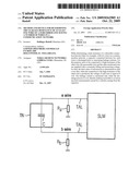
[0005]FIG. 1 then shows by way of example the basic diagrammatic structure of a current analogue subscriber connection of a telephone network.
[0006]In this arrangement, the respective subscribers TN are connected to a subscriber line module SLM allocated to the switching equipment via the corresponding subscriber line TAL. The subscriber line TAL itself usually consists of conventional twin copper wires, the two terminals being designated as a wire and b wire, respectively.
[0007]The circuit of the terminal connected to the subscriber line TAL corresponds to a capacitance C connected between the ends of the a wire and b wire in almost all terminals. This capacitance C is also called ringer capacitance since it is the component of the terminal which acquires the alternating voltage applied to the subscriber line TAL by the switching center in the event of an incoming call, that is to say which detects the incoming call.
[0008]Furthermore, FIG. 1 shows two leakage resistances Ra and Rb which represent the connections for the leakage currents between the two wires a and b of the subscriber line and ground.
[0009]In a method according to the prior art for determining these leakage resistances Ra and Rb and of the transmission-line constant (RC measurement) , a problem occurs: in the current method, the ringer capacitance C also falsifies the measured values of the leakage currents on the wires (a and b) of the subscriber line TAL.
[0010]This measuring method according to the prior art will be described in the text which follows, with reference to FIG. 2.
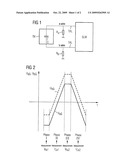
[0011]FIG. 2 represents by way of example the sequence in time of a method for determining both the resistance between line and ground and the capacitance between line and ground on the a wire of a subscriber line of an analogue telephone connection.
[0012]During an RC measurement of the a wire, the second wire b is initially switched to high impedance. Following this, a voltage having the variation with time shown in FIG. 2 is applied to the line wire a to be measured.
[0013]In this process, a constant (in the present example negative) voltage UaG is first applied to the a wire. During this phase (I), the ohmic leakage current I.sub.Ra1 between wire a and ground is measured.
[0014]Following this, a constant rising voltage UaG is applied to the a wire (phase II). During this second phase, the variation of the capacitor current I.sub.Ca1 is measured. During the measurement, the voltage UaG applied to the b wire constantly rises from the negative area up to a predeterminable positive value.
[0015]After this maximum value has been reached, the voltage UaG is then kept constant (phase III). During the third phase, too, the ohmic leakage current is now measured. Thus, a second value is obtained for the leakage current, called I.sub.Ra2 in this case.
[0016]To conclude the measurement, the applied voltage UaG is constantly reduced in phase IV. During this process, the current variation of the capacitive current of the subscriber line, here called I.sub.Ca2, is measured a second time. Starting from the predeterminable positive value, the voltage UaG then decreases to a predetermined negative value.
[0017]From these four values I.sub.Ra1, I.sub.Ra2, I.sub.Ca1, and I.sub.Ca2 detected during the measurement, leakage resistance and transmission-line constant of the a wire of the subscriber line can then be determined. To determine the corresponding values for the second wire b of the subscriber line, the steps described above are carried out with correspondingly exchanged starting positions.
[0018]As already mentioned above, the disadvantageous factor in the method described above for RC measurement is the fact that the ringer capacitance arranged between the two wires a and b falsifies the values for I.sub.Ra1 and I.sub.Ra2, respectively.
[0019]The invention is based on the object of improving the method for determining the leakage resistance of at least one wire of a subscriber line having a number of wires in a communication network. This object is achieved, starting from a method according to the features of the preamble of claim 1, by its characterizing features and starting from a device according to the features of the preamble of claim 9, by its characterizing features.
[0020]In the method according to the invention for determining the leakage resistance of at least one wire of a subscriber line having a number of wires in a communication network, a capacitance which can be arranged between the at least one wire and a further wire is discharged before the determination of the leakage resistance of the at least one wire.
[0021]The capacitance is advantageously discharged by applying a decreasing voltage to the at least one wire and applying a rising voltage to the other wire and subsequently switching the further wire to high impedance--claim 2.
[0022]In this process, the final values of the decreasing voltage and of the rising voltage are advantageously selected in such a manner that the voltage on the further wire is 0 volts after the further wire has been switched to high impedance--claim 3.
[0023]According to a further advantageous embodiment of the invention, the leakage resistance of the at least one wire is determined after the further wire has been switched to high impedance--claim 4.
[0024]In addition, the leakage resistance is advantageously determined by at least one measurement of the leakage current on the one wire of the subscriber line, the at least one measurement of the leakage current advantageously being performed with a constant applied voltage--claims 5 and 6.
[0025]Advantageously, two measurements of the leakage current are furthermore performed, the capacitance being discharged again before the second measurement--claim 7.
[0026]Further advantageous embodiments and a device for determining the leakage resistance of at least one wire of a subscriber line having a number of wires in a communication network can be found in the further claims.
[0027]The invention will be explained in greater detail with the aid of the attached drawings, in which:
[0028]FIG. 1 shows the basic diagrammatic structure of a current analogue subscriber connection of a telephone network,
[0029]FIG. 2 shows the variation with time of a method for determining the leakage resistance and the transmission-line constant on the a wire of a subscriber line according to the prior art, and
[0030]FIG. 3 shows the variation with time of the method according to the invention for determining the leakage resistance, wherein in this example, the transmission-line constant on the a wire is additionally determined in accordance with a conventional method of a subscriber line.
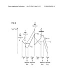
[0031]FIG. 3 shows the variation with time of the method for determining the resistance between wire and ground of a subscriber line according to the invention. The method is described here by way of example by using a combined determination of leakage resistance and transmission-line constant (RC measurement) of the a wire of a subscriber line comprising two wires (a and b).
[0032]In the method according to the invention, both a wire and b wire of the subscriber line are switched to low impedance at the beginning. In the first step (phase I), a constantly decreasing voltage UaG (illustrated by a continuous line) is applied to the wire a to be measured, wherein, due to the coupling of the two wires a and b, the voltage UbG (illustrated by a dashed line) on the second wire b has a corresponding, constantly rising variation at the same time. The two voltages UaG and UbG, respectively, in each case reach a predeterminable final value.
[0033]At the beginning of phase II, wire b is then switched to high impedance. By suitably selecting the final or target voltages set in the first step, the voltage UbG (b wire to ground) drops to 0 volts due to this switching of the b wire to high impedance as a result of which capacitance C is discharged. At the same time, a corresponding drop in the voltage UaG (a wire to ground) to a lower, negative level occurs. The voltage UaG is then kept constantly at the said level and a first measurement of the ohmic current on the a wire I.sub.Ra1 is performed.
[0034]After the conclusion of this measurement, a constantly rising voltage is applied to wire a (phase III) until the voltage UaG has reached a predeterminable positive value. During this voltage increase on wire a, the variation of the capacitive current I.sub.Ca1 on this wire is measured. Due to the increasing voltage on the a wire, the voltage UbG between b wire and ground increases at the same time (dashed line) as shown in FIG. 3.
[0035]After the conclusion of the measurement of I.sub.Ca1 and after the maximum voltage has been reached, the b wire of the subscriber line is switched to low impedance again at the beginning of phase IV. By switching to low impedance, wire b is pulled to a lower voltage level, on the one hand, whilst UaG also drops, on the other hand. In this case, the voltage between wire and ground (UaG) drops to a negative voltage value.
[0036]Following this, according to the exemplary method, the same procedure as in phase I is adopted for a second measurement of the leakage current--but with opposite signs. I.e. in phase IV, a constantly rising voltage is applied to wire a as a result of which wire b is supplied with a constantly dropping voltage at the same time. In this example, both voltages UaG and UbG pass through the zero point and finally in each case reach a predeterminable target value as final voltages.
[0037]In phase V, wire b is then switched to high impedance again. A suitable adjustment of the final or peak voltages of UaG and UbG in phase IV leads to the voltage of b wire to ground UbG again being pulled to 0 volts. At the same time, voltage UaG (voltage between a wire and ground) rises to a correspondingly higher value. Following this new switching of the b wire to high impedance, the voltage UaG is kept constant and a second measurement of the ohmic current I.sub.Ra2 is performed. In this second measurement, too, the following applies: UbG=0 volts.
[0038]Finally, a constantly dropping voltage is applied to wire a in phase VI. During this phase, a second measurement of the capacitive current I.sub.Ca2 on the a wire is carried out whilst the a wire to ground voltage UaG decreases down to a predeterminable negative value.
[0039]Following the sequence of the method according to the invention, the values of the leakage resistance and the transmission-line constant of the a wire of the subscriber line can be determined in conventional manner from the detected measurement values I.sub.Ra1, I.sub.Ca1, I.sub.Ra2 and I.sub.Ca2. As mentioned above, this method according to the invention does not result in any faulty measurements of the ohmic currents I.sub.Ra1 and I.sub.Ra2, respectively, since the ringer capacitance C is in each case discharged before the currents are measured.
[0040]To determine the values for the b wire, that is to say to perform a corresponding RC measurement of the b wire, the method according to the invention can also be used correspondingly on the second wire b of the subscriber line.
User Contributions:
comments("1"); ?> comment_form("1"); ?>Inventors list |
Agents list |
Assignees list |
List by place |
Classification tree browser |
Top 100 Inventors |
Top 100 Agents |
Top 100 Assignees |
Usenet FAQ Index |
Documents |
Other FAQs |
User Contributions:
Comment about this patent or add new information about this topic:
Images included with this patent application:
 |  |
 |
| Top Inventors for class "Telephonic communications" | |
| Rank | Inventor's name |
|---|---|
| 1 | Robert C. Steiner |
| 2 | Herbert Willi Artur Ristock |
| 3 | At&t Intellectual Property I, L.p. |
| 4 | Peeyush Jaiswal |
| 5 | Douglas Brown |