Patent application title: SEALING DEVICE FOR TWIN ROLL CASTER
Inventors:
Shiro Osada (Tokyo, JP)
Hisahiko Fukase (Tokyo, JP)
Hisahiko Fukase (Tokyo, JP)
Assignees:
IHI CORPORATION
IPC8 Class: AB22D11106FI
USPC Class:
164428
Class name: Continuous or semicontinuous casting continuously advancing mold part roll couple mold
Publication date: 2009-10-01
Patent application number: 20090242162
Inventors list |
Agents list |
Assignees list |
List by place |
Classification tree browser |
Top 100 Inventors |
Top 100 Agents |
Top 100 Assignees |
Usenet FAQ Index |
Documents |
Other FAQs |
Patent application title: SEALING DEVICE FOR TWIN ROLL CASTER
Inventors:
Shiro Osada
Hisahiko Fukase
Agents:
OBLON, SPIVAK, MCCLELLAND MAIER & NEUSTADT, P.C.
Assignees:
IHI Corporation
Origin: ALEXANDRIA, VA US
IPC8 Class: AB22D11106FI
USPC Class:
164428
Patent application number: 20090242162
Abstract:
A sealing device for a main roller coaster including a transition piece
positioned above a melt pool formed between chilled rolls, rotatable
cylindrical brushes extending axially of the rolls and each abutting
against an outer periphery of the corresponding roll all over an axial
length thereof on a side away from the pool and below the transition
piece, first cowlings each covering the roll in between the transition
piece and the brush, second cowlings each surrounding a portion of the
brush not in contact with the roll, third cowlings each covering the roll
below the brush and outlets for feeding sealing gas to between the
transition piece and the rolls, the sealing gas from the outlets filling
up to outlet portions of the third cowlings.Claims:
1. A sealing device for a twin roll caster, comprising:a transition piece
positioned above a melt pool formed between chilled rolls,rotatable
cylindrical brushes extending axially of the rolls and each abutting
against an outer periphery of the corresponding roll all over axial
length thereof on a side away from the pool and below the transition
piece,first cowlings contiguous with the transition piece and each
covering the corresponding roll in between the transition piece and the
corresponding brush,second cowlings contiguous with said first cowlings
and each surrounding a portion of the brush not in contact with the
roll,third cowlings contiguous with said second cowlings and each
covering the roll below the brush, andoutlets for feeding sealing gas in
between the transition piece and the rolls.
2. A sealing device for a twin roll caster as claimed in claim I wherein each of the brushes is set to be rotated in a same direction, looking in a direction of axis thereof, of that of rotation of the roll against which the brush abuts.
3. A sealing device for a twin roll caster as claimed in claim 1 wherein the sealing gas from the outlet and flowing between the first cowling and the roll is set to have a velocity exceeding an absolute value of a peripheral velocity of the roll.
4. A sealing device for a twin roll caster as claimed in claim 2 wherein the sealing gas from the outlet and flowing between the first cowling and the roll is set to have a velocity exceeding an absolute value of a peripheral velocity of the roll.
Description:
TECHNICAL FIELD
[0001]The present invention relates to a sealing device for a twin roll caster.
Background Art
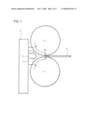
[0002]FIG. 1 shows an example of a twin roll caster comprising a pair of chilled rolls 1 arranged horizontally side by side and a pair of side weirs 2 associated with the rolls 1.
[0003]The rolls 1 are constructed such that cooling water passes through interiors of the rolls and that a nip G between the rolls may be adjusted to be increased or decreased depending upon thickness of a steel strip 3 to be produced.
[0004]The velocity and direction of rotation of the rolls 1 are set such that the outer peripheries of the respective rolls 1 move from above towards the nip G at the same velocity.
[0005]One of the side weirs 2 surface-contacts one ends of the rolls 1 and the other side weir 2, the other ends of the rolls 1. Above a space defined by the rolls 1 and the side weirs 2, a transition piece 4 is arranged to surface-contact upper ends of the side weirs 2.
[0006]A melt supplying nozzle 5 is incorporated in the transition piece 4 so as to be positioned just above the nip G. By supplying melt from the nozzle 5 to the space defined by the rolls 1 and the side weirs 2, a melt pool 6 is formed.
[0007]Specifically, with the pool 6 being formed, the rolls 1 are rotated while cooled through passage of cooling water, melt solidifies on outer peripheries of the rolls 1, a resultant strip 3 being delivered downward from the nip G.
[0008]In such a twin roll caster, a cover is provided to cover the melt pool 6 and inert gas is fed inside the cover to prevent oxidation of the melt.
[0009]A melt-pool cover with rotary bodies has been proposed, each of the rotary bodies wrapped with woven cloth being arranged to abut against an outer surface of the cover and against an outer periphery of the corresponding roll 1 all over axial length thereof so that the woven cloth may suppress invasion of atmospheric air inside the cover (see, for example, Reference 1).
[0010]Nitrogen is generally used as inert gas to be fed inside the cover. In order to make the strip 3 thin in thickness, argon, which is relatively low in heat conductivity, is mixed with nitrogen and the mixture is fed inside the cover; then, heat of the melt becomes less transmittable to the rolls 1 to suppress temperature increase of the outer peripheries of the rolls 1, so that the strip 3 thin in thickness can be obtained without especially lowering rotating velocity of the rolls and without causing development of strip breakage due to insufficient production of solidification shells.
[0011][Reference 1] JP Patent 2760695
SUMMARY OF THE INVENTION
Problems to be Solved by the Invention
[0012]However, even if the interior of the cover is changed from that with pure nitrogen atmosphere into that with argon-containing nitrogen atmosphere, ten minutes or more are required before the outer peripheries of the rolls 1 are lowered in temperature.
[0013]This results from a fact that, during rotation of the rolls 1, textures (regular concavities and convexities of the order of several tens of micrometers) on the outer peripheries of the rolls are clingingly accompanied by the atmospheric air, resulting in difficulty for the argon-containing nitrogen to contact the rolls.
[0014]Moreover, in Reference 1, a direction of rotation of the rotary body is, when seeing axially thereof, contradictory to that of the roll 1 against which the rotary body abuts, so that the atmospheric air is pinched between the rotary body and the roll 1, which facilitates accompaniment of the atmospheric air to the roll 1.
[0015]The invention was made in view of the above and has its object to provide a sealing device for a twin roll caster which can suppress accompaniment of the atmospheric air to the rolls.
Means or Measures for Solving the Problems
[0016]In order to attain the above object, the invention comprises a transition piece positioned above a melt pool formed between chilled rolls, rotatable cylindrical brushes extending axially of the rolls and each abutting against an outer periphery of the corresponding roll all over axial length thereof on a side away from the pool and below the transition piece, first cowlings contiguous with the transition piece and each covering the corresponding roll in between the transition piece and the corresponding brush, second cowlings contiguous with said first cowlings and each surrounding a portion of the brush not in contact with the roll, third cowlings contiguous with said second cowlings and each covering the roll below the brush and outlets for feeding sealing gas in between the transition piece and the rolls.
[0017]In the invention, the sealing gas from each of the outlets is guided by the first, second and third cowlings covering the corresponding roll and the brush to flow in a direction contradictory to a direction of rotation of the roll.
[0018]In addition, the brush is rotated in the same direction as that of rotation of the roll against which the brush abuts; alternatively, the sealing gas flowing along the outer periphery of the roll is set to have a velocity exceeding an absolute value of a peripheral velocity of the roll.
Effects of the Invention
[0019]A sealing device for a twin roll caster according to the invention can exhibit the following excellent effects and advantages:
[0020](1) The fact that the sealing gas from each of the outlets is guided by the first, second and third cowlings covering the corresponding roll and brush to flow in a direction contradictory to the direction of rotation of the roll can suppress accompaniment of the atmospheric air to the roll.
[0021](2) When the brush is rotated in the same direction as that of rotation of the corresponding roll or the sealing gas is set to have the velocity exceeding the absolute value of the peripheral velocity of the roll, accompaniment of the atmospheric air to the roll can be further effectively suppressed.
[0022](3) Thus, when the space above the melt pool is changed from that with pure nitrogen atmosphere into that with argon-containing nitrogen atmosphere, the outer peripheries of the rolls are lowered in temperature within a shorter time than ever; when the space is changed from that with argon-containing nitrogen atmosphere into that with pure nitrogen atmosphere, the outer peripheries of the rolls are raised in temperature within a similarly shorter time than ever, so that strips with different thicknesses can be effectively produced.
BRIEF DESCRIPTION OF THE DRAWINGS
[0023]FIG. 1 is a schematic view showing an example of a conventional twin roll caster; and
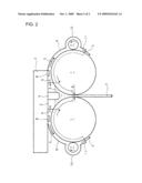
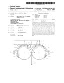
[0024]FIG. 2 is a schematic view showing an embodiment of a sealing device for a twin roll caster according to the invention.
EXPLANATION OF THE REFERENCE NUMERALS
[0025]1 chilled roll [0026]4 transition piece [0027]6 melt pool [0028]7 brush [0029]8 outlet [0030]9 first cowling [0031]10 second cowling [0032]11 third cowling
BEST MODE FOR CARRYING OUT THE INVENTION
[0033]An embodiment of the invention will be described in conjunction with the drawings.
[0034]FIG. 2 shows the embodiment of a sealing device for a twin roll caster according to the invention in which parts similar to those in FIG. 1 are represented by the same reference numerals.
[0035]The sealing device for the twin roll caster comprises rotatable cylindrical brushes 7 extending axially of the rolls 1, outlets 8 for discharging sealing gas S such as pure or argon-containing nitrogen, and first, second and third cowlings 9, 10 and 11 associated with each of the rolls 1 to provide a flow passage for the sealing gas S.
[0036]Each of the brushes 7 is arranged below the transition piece 4 to abut against an outer periphery of the corresponding roll 1 all over axial length thereof on a side away from a melt pool 6 and is rotatable by drive mechanism such as motor in a same direction, when seeing axially, as that of rotation of the roll 1 against which the brush 7 abuts.
[0037]The outlet 8 is mounted on a bottom of the transition piece so as to be positioned just above each of the rolls 1.
[0038]The first cowling 9 is contiguous with the bottom of the transition piece 4 and covers the outer periphery and end peripheral borders of the roll 1 in between the transition piece 4 and the brush 7.
[0039]A distance between the first cowling 9 and the outer periphery of the roll 1 is set to be 5-10 mm.
[0040]The second cowling 10 is contiguous with the first cowling and surrounds a portion of the brush 7 not in contact with roll 1 to cover an adjacent outer periphery portion and end peripheral borders of the roll 1.
[0041]A distance between the second cowling 10 and the outer periphery of the brush 7 is set to be less than 10 mm so that dusts may not enter into the first cowling 9 due to rotation of the brush 7.
[0042]The third cowling 11 is contiguous with the second cowling 10 and covers the outer periphery and end peripheral borders of the roll 1 below the brush 7.
[0043]A distance between the third cowling 11 and the outer periphery of the roll 1 is set to be substantially equal to the above-mentioned distance between the first cowling 9 and the outer periphery of the roll 1 or to be within three times as much as that.
[0044]The third cowling 11 is set to have length along the periphery of the roll 1 of 50 mm or more, so that the sealing gas S from the outlet 8 is adapted to fill up to an outlet portion of the third cowling 11 so as to prevent the atmospheric air from entering inside of the third cowling 11.
[0045]Sum in flow rate of the sealing gas S from the two outlets 8 is set such that a velocity of the sealing gas S flowing between the first cowling 9 and the roll 1 exceeds an absolute value of a peripheral velocity (2 m/second) of the roll 1.
[0046]For example, assume that the distance between the first cowling 9 and the outer periphery of the roll 1 (cowling-roll distance) is 10 mm, length of the roll 1 (roll length) being 1350 mm, sum in flow rate of the sealing gas S from the two outlets 8 (gas discharge rate) being 150 m3/minute; then, flow rate of the sealing gas S (gas flow rate) flowing between the first cowling 9 and the roll 1 is 93 m/minute or so from the following relationship.
[0047]gas flow rate=gas discharge rate/roll number×roll length×cowling-roll distance
[0048]Specifically, the sealing gas S from the outlet 8 is guided by the first, second and third cowlings 9, 10 and 11 covering the roll 1 and the brush 7 so as to flow with velocity exceeding the absolute value of the peripheral velocity of the roll 1 and in a direction contradictory to that of rotation of the roll 1, the brush 7 in contact with the roll 1 being rotated in the same direction as that of rotation of the roll 1, so that accompaniment of the atmospheric air to the roll 1 can be effectively suppressed.
[0049]As a result, when the space between the pool 6 and the transition piece 4 is changed from that with pure nitrogen atmosphere to that with argon-containing nitrogen atmosphere, the outer periphery of the roll 1 is lowered in temperature in a shorter time than ever; on the contrary, when the space between the pool 6 and the transition piece 4 is changed from that with argon-containing nitrogen atmosphere into that with pure nitrogen atmosphere, the outer periphery of the roll 1 is raised in temperature in a similarly shorter time than ever. Thus, strips with different thicknesses can be efficiently produced.
[0050]It is to be understood that a sealing device for a twin roll caster according to the invention is not limited to the above embodiment and that various changes and modifications may be made without departing from the scope of the invention.
INDUSTRIAL APPLICABILITY
[0051]A sealing device for a twin roll caster according to the invention is applicable to production of not only steel strips but also other various metal strips.
User Contributions:
comments("1"); ?> comment_form("1"); ?>Inventors list |
Agents list |
Assignees list |
List by place |
Classification tree browser |
Top 100 Inventors |
Top 100 Agents |
Top 100 Assignees |
Usenet FAQ Index |
Documents |
Other FAQs |
User Contributions:
Comment about this patent or add new information about this topic:
| People who visited this patent also read: | |
| Patent application number | Title |
|---|---|
| 20160142933 | Fair Distribution of Radio Resources Between Guaranteed Bit Rate (GBR) and non-GBR Data Bearers |
| 20160142932 | EVOLVED DATA COMPRESSION SCHEME FOR UNRELIABLE TRANSMISSION MODES |
| 20160142931 | AUTOMATED MEASUREMENT AND ANALYSIS OF END-TO-END PERFORMANCE OF VoLTE SERVICE |
| 20160142930 | Enterprise Cognitive Radio Integrated With Laser Communications |
| 20160142929 | METHOD OF SPATIAL SHARING IN WIRELESS COMMUNICATIONS SYSTEM |
Images included with this patent application:
 |  |
 |
| Similar patent applications: | |
| Date | Title |
|---|---|
| 2013-08-01 | Molding device for continuous casting equipped with agitator |
| 2012-06-07 | Self supporting core-in-a-core for casting |
| 2013-08-08 | Fabrication of hybrid solid-porous medical implantable devices with electron beam melting technology |
| 2013-08-01 | Method and plant for the energy-efficient production of hot steel strip |
| 2010-08-26 | Casting process for aluminum alloys |
| New patent applications in this class: | |
| Date | Title |
|---|---|
| 2014-09-18 | Casting delivery nozzle |
| 2013-09-19 | Ultra-thin slab or thick-strip casting |
| 2012-01-19 | Operating method for twin-roll casting machine, and side weir supporting device |
| 2010-12-02 | Casting roll for a two-roll casting device and two-roll casting device |
| 2010-09-30 | Stationary side dam for continuous casting apparatus |
| New patent applications from these inventors: | |
| Date | Title |
|---|---|
| 2013-05-16 | Casting thin strip and delivery nozzle therefor |
| 2013-04-18 | Casting thin strip and delivery nozzle therefor |
| 2013-04-11 | Twin roll caster and method of control thereof |
| 2012-11-01 | Twin roll caster and method of control thereof |
| 2009-12-03 | Twin-roll casting machine |
| Top Inventors for class "Metal founding" | |
| Rank | Inventor's name |
|---|---|
| 1 | Theodore A. Waniuk |
| 2 | Steven J. Bullied |
| 3 | Joseph C. Poole |
| 4 | Carl R. Verner |
| 5 | Christopher D. Prest |