Patent application title: ELECTRICAL SUBMERSIBLE PUMP AND GAS COMPRESSOR
Inventors:
Peter Francis Lawson (Tulsa, OK, US)
IPC8 Class: AE21B4334FI
USPC Class:
1661055
Class name: Wells with eduction pump or plunger having liquid-gas separator
Publication date: 2009-06-18
Patent application number: 20090151928
Inventors list |
Agents list |
Assignees list |
List by place |
Classification tree browser |
Top 100 Inventors |
Top 100 Agents |
Top 100 Assignees |
Usenet FAQ Index |
Documents |
Other FAQs |
Patent application title: ELECTRICAL SUBMERSIBLE PUMP AND GAS COMPRESSOR
Inventors:
Peter Francis Lawson
Agents:
BRACEWELL & GIULIANI LLP
Assignees:
Origin: HOUSTON, TX US
IPC8 Class: AE21B4334FI
USPC Class:
1661055
Abstract:
A wellbore fluid production system that is disposable in a wellbore
comprising a separator, a pump, a compressor, and a motor. The separator
segregates the gas and liquid and delivers the gas to the compressor
inlet and the liquid to the pump inlet. The pump pressurizes the liquid
for delivery to the surface. The compressor pressurizes the gas for
reinjection into the wellbore, injection into another subterranean
formation, or for delivery to the surface.Claims:
1. A fluid production system for delivering wellbore fluids comprising:a
gas liquid separator having an inlet configured to receive subterranean
wellbore fluid, a gas exit configured to discharge gas from within the
fluid from the separator, and a liquid exit configured to discharge
liquid within the fluid from the separator;a pump having an inlet formed
to receive liquid from the liquid exit;a compressor having an inlet
formed to receive gas from the gas exit; anda motor mechanically coupled
to the separator, pump, and compressor, wherein the system is disposed in
a conduit.
2. The fluid handling system of claim 1 wherein the pump is connected between the gas separator and the compressor.
3. The fluid handling system of claim 2, further comprising a vapor bypass line extending from the gas exit alongside the pump and leading to the compressor inlet.
4. The fluid handling system of claim 1 further comprising a vapor bypass line providing fluid communication between the gas exit and the compressor inlet.
5. The fluid handling system of claim 2 further comprising a speed/torque converter mechanically coupled between the pump and the compressor for rotating the compressor faster than the pump.
6. The fluid handling system of claim 1 wherein the compressor has an outlet connected to a gas flow passage and the pump has an outlet connect to a liquid flow passage.
7. The fluid handling system of claim 5 further comprising a liquid bypass line extending alongside the converter and leading from an outlet of the pump to a liquid flow conduit.
8. The fluid handling system of claim 1, further comprising a concentric flow line extending from the compressor, having an inner and an annular passage, and wherein liquid from the pump is discharged through one of the passages and gas from the compressor is discharged into the other.
9. A method of producing a two phase gas liquid mixture of wellbore fluid, the method comprising:separating the gas and liquid mixture into a substantially mono-phase gas component and a substantially mono-phase liquid component;pumping the mono-phase liquid component; andcompressing the mono-phase gas component, wherein the steps of separating, pumping and compressing are performed by a device disposed in a conduit.
10. The method of claim 9, further comprising flowing the liquid component from the pump and the gas component from the gas separator in separate passages leading out of the conduit.
11. The method of claim 9 wherein the device comprises a gas separator, a pump, and a compressor, and the method further comprises flowing liquid from the pump past the compressor to a liquid passage leading out of the conduit.
12. The method of claim 11, further comprising flowing liquid from the pump past the compressor to a liquid passage leading out of the conduit.
13. The method of claim 9 wherein the step of separating is performed using a rotary submersible wellbore gas separator.
14. The method of claim 9, wherein the step of pumping is performed using an electrical centrifugal pump.
15. The method of claim 9, wherein the step of compressing is performed using a compressor selected from the list consisting of a radial flow gas compressor and an axial flow gas compressor.
16. The method of claim 9, wherein the device comprises a separator, a centrifugal pump, a gas compressor, and a motor that drives the separator, pump, and gas compressor.
17. A system for pressurizing two phase wellbore fluid flowing into a conduit comprising:an electrical motor assembly within the conduit;a rotary gas liquid separator in the conduit and mounted to the motor assembly the separator having an inlet, a gas exit, and a liquid exit;a centrifugal pump mounted to the separator liquid exit;a rotary compressor assembly mounted to the gas exit; anda gas bypass line extending from the separator gas exit alongside the pump to the compressor.
18. The system of claim 17 wherein the compressor assembly includes a torque/speed converter to drive the compressor at a higher speed than the pump.
19. The system of claim 17, further comprising a barrier in the conduit defining a separate chamber in the conduit for the inlet of the gas separator.
20. The system of claim 17 further comprising an inner passage and an annular passage, a concentric flow line extending from the compressor, a liquid bypass line extending from an outlet of the pump alongside the compressor to one of the passages, and the compressor having an outlet coupled to the other of the passages.
Description:
BACKGROUND
[0001]1. Field of Invention
[0002]The present disclosure relates to a fluid handling system used for producing downhole fluids. More specifically, the present disclosure concerns a fluid handling system having an electrical submersible pump combined with a compressor.
[0003]2. Description of Prior Art
[0004]Submersible pumping systems are often used in hydrocarbon producing wells for pumping fluids from within the well bore to the surface. These fluids are generally liquids and include produced liquid hydrocarbon as well as water. One type of system used in this application employs an electrical submersible pump (ESP). Typically ESP's employ centrifugal pumps with multiple stages of impellers/diffusers. These systems are particularly used in wells that produce a large amount of water in ratio to the oil. ESPs are typically disposed at the end of a length of production tubing and have an electrically powered motor. Often, electrical power may be supplied to the pump motor via an ESP power cable.
[0005]In many oil wells, gas is also produced with the liquid hydrocarbon. The liquid usually comprises hydrocarbon, and water.
[0006]In certain applications the pump intake is positioned above where the connate fluid enters the wellbore, and thus gas may enter the inlet. Most ESP's are designed for pumping incompressible liquids and not gas. If too much gas is delivered to a pump it will lose efficiency because of the compressibility of gas. To overcome this problem gas separators are employed to extract gas from the mixture thereby diverting from the pump inlet. A gas separator separates a mixture of liquid and gas typically by centrifugal force. The liquid flows through a central area into the intake of the pump. The gas is discharged out gas discharge ports into the annulus surrounding the pump. Gas in the annulus collects at the surface of the well and is often introduced through a check valve hack into the production flowline at the surface.
[0007]The produced gas may be pressurized if it has insufficient pressure to flow to surface or if the gas is to be re-injected into a subterranean formation. Reinjecting the gas may be for promoting hydrocarbon production from that formation, or it may ultimately be delivered to subterranean storage. An example of a centrifugal gas compressor comprises stages of rotating impellers within stators or diffusers. However, the design is such that compressors compress gas and not pump a liquid. Generally, a centrifugal gas compressor must operate at a much higher rotational speed than a liquid pump.
SUMMARY OF INVENTION
[0008]The present disclosure includes a fluid production system for delivering wellbore fluids comprising, a gas liquid separator having an inlet configured to receive subterranean wellbore fluid, a gas exit configured to discharge gas from within the fluid from the separator, and a liquid exit configured to discharge liquid within the fluid from the separator. Also included with the system is a pump having an inlet formed to receive liquid from the liquid exit, a compressor having an inlet formed to receive gas from the gas exit, and a motor mechanically coupled to the separator, pump, and compressor, wherein the system is disposed in a conduit.
BRIEF DESCRIPTION OF DRAWINGS
[0009]Some of the features and benefits of the present invention having been stated, others will become apparent as the description proceeds when taken in conjunction with the accompanying drawings, in which:
[0010]FIG. 1 illustrates a side partial cut-away view of a fluid production system.
[0011]FIG. 2 portrays in partial cut-away side view a fluid delivery system.
[0012]FIGS. 3A and 3B depict in a cross sectional view a portion of the fluid delivery system.
[0013]FIGS. 4 and 5 show in cross sectional views embodiments of a compressor.
[0014]FIG. 6 illustrates in side cross sectional view an embodiment of a pump.
[0015]While the invention will be described in connection with the preferred embodiments, it will be understood that it is not intended to limit the invention to that embodiment. On the contrary, it is intended to cover all alternatives, modifications, and equivalents, as may be included within the spirit and scope of the invention as defined by the appended claims.
DETAILED DESCRIPTION OF INVENTION
[0016]The present invention will now be described more fully hereinafter with reference to the accompanying drawings in which embodiments of the invention are shown. This invention may, however, be embodied in many different forms and should not be construed as limited to the illustrated embodiments set forth herein; rather, these embodiments are provided so that this disclosure will be through and complete, and will fully convey the scope of the invention to those skilled in the art. Like numbers refer to like elements throughout.
[0017]The present disclosure provides embodiments of a fluid delivery system for use in producing wellbore fluids. More specifically, disclosed herein is a system having a device and method for producing subterranean wellbore fluid. A device is included which is disposable within a conduit, and where the device can accommodate a two phase flow and separately produce the components of a two phase flow. The conduit may be one of a casing or a fluids handling circuit, such as a caisson. The use of the device is also applicable to subsea applications wherein a jumper extends from one wellhead to another wellhead or alternatively a jumper communicates between a wellhead and a manifold. The device disposable in the conduit is modular, self contained, and fully powered within a single unit. The device comprises a gas/liquid separator, a pump for pumping the liquid extracted from the two phase mixture, a compressor for compressing the gas extracted from the two phase mixture, and a motor for driving the separator, pump, and compressor.
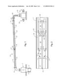
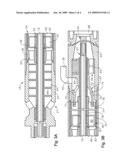
[0018]FIG. 1 provides a side and partial cross sectional view of a production system 10 for producing wellbore fluids. The production system comprises a production line 12, also referred to herein as a jumper line, a subsea production tree 7 and a manifold 30. The wellhead 7 is in fluid communication with a cased wellbore 5 wherein the cased wellbore (possibly with associated production tubing) delivers production fluids through the wellhead 7. The production fluids may be a two phase mixture of a gas and liquid. The fluid, represented by the arrow, enters the production system 10 through the production line 12 and flows to the fluid delivery system 14. The fluid delivery system 14, shown in side view coaxially disposed within the production line 12, comprises a motor 16, a separator 18, a pump 20, a gear reducer 22, and compressor 24. The flow continues through the production line 12 and when encountering the fluid delivery system 14 flows in the annulus 15 formed between the delivery system 14 and the inner circumference of the production line 12. Flowing past the motor section 16, the flow then enters the inlet 21 of the separator 18.
[0019]In the separator 18, as will be described in more detail below, the two phase flow is separated into gas and liquid components. A liquid line, is connected to the exit of the separator and supplies liquid to the pump 20. Similarly, a gas line is provided at the gas exit of the separator 18 flow providing inlet gas flow to the compressor 24. Packers 26 may be included in the annulus between the fluid delivery system 14 and the production line 12 inner circumference to ensure the flow is directed into the inlet 21. At the exit of the delivery system 14 a discharge line 28 is shown for directing the individual components of the flow to the associated manifold 30.
[0020]Optionally, the gas and liquid may flow in separate tubing (not shown) provided within the discharge line 28. Alternatively either the pressurized liquid or the compressed gas may be directed through the discharge line 28 with the other fluid flowing in the annular space between the discharge line 28 and the production line 12. The manifold 30 is shown having optional features, such as a manifold intake 32 and manifold exit 34. Produced fluids from other wellbores may be combined in the manifold 30 with fluids produced from the wellbore 5. In some instances it may be desirable to inject compressed gas into the wellbore 5, into another wellbore, or into subterranean storage. Accordingly, the discharge pressure of the compressor 24 is adjustable to ensure sufficient pressure for the particular gas injection scenario. Alternatively, however, the manifold exit 34 may direct all fluids to the surface for production.
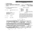
[0021]Referring now to FIG. 2, a schematic illustration of the fluid delivery system 14 is shown in a side view. In this illustration, the delivery system 14 is coaxially disposed within a conduit 11. The conduit 11 can be either the production line 12 or the casing 4 cemented within the wellbore 5. In the embodiment of FIG. 2, inlets 21 receive two phase fluid (represented by the arrows) therein for delivery to the separator 18. The exit of the separator 18 includes some vapor lines 38, also referred to as bypass lines, that deliver the separated gas to the compressor 24. Schematically illustrated by parallel arrows, liquid flow from the separator is delivered to the pump 20 for pressurizing therein. A high pressure seal 42 may optionally be provided at the downstream end of pump 20. A shaft 19 is extending from the motor 17 through each of the separator 18, pump 20, and compressor 24. The shaft 19, as will be described later, may be a single unit, or may be comprised of multiple shafts having couplings at the junction of each piece of the rotating equipment that make up the fluid delivery system 14. A gear reducer 22 is provided at the mechanical power intake of the compressor 24. Since most compressors operate at higher RPM's than either a separator or pump, it is necessary to convert a portion of the torque into a higher rotational speed. It is believed that it is within the capabilities of those skilled in the art to produce an appropriate gear reducer to achieve this desired resulting torque and rotational speed. The pump discharge and compressed gas lines may be run separate from one another, optionally these lines may be coaxially piped with one inside of the other.
[0022]FIGS. 3A and 3B provide a side cross sectional view of one example of the separator 18. A variety of different types of separators could be employed. As shown, the gas separator 18 comprises two or more individual units. Separator 18 comprises a generally cylindrical housing 23 wherein the shaft 19 coaxially extends therethrough. Couplings are provided on opposing ends of the shaft 19 for connection to other rotating machinery within the system 14. An inlet 21 extending through the bottom portion of the housing 23 provides the fluid flow pathway for receiving wellbore fluid.
[0023]After passing through the inlet 21 well fluid encounters an inducer 46 that comprises a helical screw mounted to the shaft 19 for rotation therewith. The inducer 46 conveys the fluid upward and pressurizes the fluid to prevent expansion of the gas contained within the fluid at that point. Well fluid then passes through a bearing 48, optionally shown as a spider type bearing, having a plurality of passages 50. Upon leaving the bearing 48, the well fluid is directed to a set of guide vanes 52 that are mounted onto the shaft 19 as well. Preferably, more than one guide vane 52 is provided and each comprises a flat or a curved plate being inclined relative to the shaft axis. The guide vanes 52, when rotating with respect to the fluid, impart a swirling motion to the well fluid directing it to the inner circumference of the housing 23.
[0024]The guide vanes 52 are located in the lower portion of a rotor 54 that has an outer cylinder 56 extending down and over the guide vanes 52. The outer cylinder 56 encloses an inner hub 60 and is closely spaced within a stationary sleeve 58 mounted in the passage 44. The inner hub 60 mounts to the shaft 19 for rotation with the shaft. Vanes 62 (only two are shown in the figure) extend between the hub 60 and the outer cylinder 56. Vanes 62 comprise longitudinal blades extending from the lower end to the upper end of the rotor 54. Each vane 62 is located in a plane radial to the axis of the shaft 19, and each vane 62 is vertically oriented.
[0025]With reference now to FIG. 3B, the upper portion of the separator is shown. Each vane 62 has a notch 76 on its upper edge. A crossover member 67 mounts stationarily above the upper rotor 80. The upper discharge member 67 has a depending skirt 75, the lower end of which extends into the notches 76. The skirt 75 defines a gas cavity 74 on its inner diameter. Three gas passages 72 lead through the upper discharge member 67, each to an upper gas outlet 70. Liquid passage 73 is located in a clearance between the skirt 75 and the inner diameter of the housing 23. A bearing 65 mounts in a housing 23 above the upper discharge member 67 for supporting the shaft 19. The bearing 65 has one or more axial passages 64 for the flow of the well fluid therethrough. The well fluid flows through a bore outlet 68 on the upper end into the intake of the pump.
[0026]In one mode of operation, the well fluid flows in through the intake 21. The inducer 46 applies pressure to the well fluid which then flows through the guide vanes 52 into the rotor 54. The spinning rotor 54 causes some separation of the gas and liquid, with the heavier liquid components moving outward toward the outer cylinder 56.
[0027]Referring to FIG. 3B, separated gas flows through the gas cavity 74, the gas passage 72, and exits the gas outlet 70. Upon exiting the gas outlet 70, the gas enters the vapor line 38 for delivery to the compressor. The remaining well fluid flows up the liquid passage 73, through the passage 64, and out the bore outlet 68 to the pump.
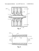
[0028]FIGS. 4 and 5 provide in a side cross sectional view examples of a radial flow compressor and an axial flow compressor. With reference now to FIG. 4, it illustrates a radial flow compressor 24a that may be used as the gas compressor 24 of FIG. 1. Typically, a radial flow compressor produces higher pressures but at a lesser flow rate than an axial flow compressor. In this embodiment, the radial flow compressor 24a comprises impellers 85 and configured to rotate with corresponding diffusers 86. The configuration is such that the flow has a radial outward and inward components from each successive stage.
[0029]FIG. 5, which illustrates an embodiment of an axial flow compressor 24b, provides flow in a generally axial direction with minimal outward/inward radial components. The axial compressor 24b comprises a tubular housing 87 with a large number of impellers 88. The impellers 88 are rotated within corresponding stators 89, which provides a function similar to that of corresponding diffusers. A corresponding shaft 27 rotates the impellers 88 within the corresponding stators/diffusers. Each stage of an impeller 88 and stator 89 results in a pressure increase.
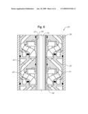
[0030]With reference now to FIG. 6, a side cross sectional view of one example of a centrifugal pump is shown. The centrifugal pump 20 comprises a housing 35 for protecting the components of the pump 20. The pump 20 comprises a shaft 19 extending longitudinally through the pump 20. Diffusers 36 comprise an inner portion with a bore 37 which through a shaft 19 extends. Each diffuser 36 comprises multiple passages 43 that extend through the diffuser 36. An impeller 41 is placed within each diffuser 36. The impeller 41 includes a bore 39 that extends to the length of the impeller 41 for rotation relative to a corresponding diffuser 36 and is engaged with the shaft 19. Optionally, thrust washers may be included and placed between the upper and lower portions of the impeller 41 and the diffuser 36.
[0031]In operation, the impellers 41 rotate along with the shaft 19 which increases the velocity of the fluid being pumped as the fluid is discharged radially outward through the passages. The fluid intake flows inward through the diffuser passages 43 and returns to the intake of the next stage impeller 41, which decreases the velocity and increases the pressure of the pumped fluid. Increasing the number of stages by adding more impellers 41 and diffusers 36 can increase the fluid pressure at the exit of the pump.
[0032]It is to be understood that the invention is not limited to the exact details of construction, operation, exact materials, or embodiments shown and described, as modifications and equivalents will be apparent to one skilled in the art. In the drawings and specification, there have been disclosed illustrative embodiments of the invention and, although specific terms are employed, they are used in a generic and descriptive sense only and not for the purpose of limitation. Accordingly, the invention is therefore to be limited only by the scope of the appended claims.
User Contributions:
comments("1"); ?> comment_form("1"); ?>Inventors list |
Agents list |
Assignees list |
List by place |
Classification tree browser |
Top 100 Inventors |
Top 100 Agents |
Top 100 Assignees |
Usenet FAQ Index |
Documents |
Other FAQs |
User Contributions:
Comment about this patent or add new information about this topic:
Images included with this patent application:
 |  |
 |  |
 |
| Similar patent applications: | |
| Date | Title |
|---|---|
| 2012-02-02 | Electric submersible pump band basket catcher |
| 2009-11-05 | Electrical submersible pump assembly |
| 2011-04-14 | Coaxial electric submersible pump flow meter |
| 2011-09-22 | Electric submersible pump service truck |
| 2012-12-13 | Well treatment using electric submersible pumping system |
| New patent applications in this class: | |
| Date | Title |
|---|---|
| 2018-01-25 | Oil production well gas separator system using progressive perforations |
| 2016-05-12 | Downhole pump seating nipple with perforations |
| 2016-03-10 | Downhole gas release apparatus |
| 2015-12-10 | Wellbore conveyor device |
| 2014-10-30 | System for the continuous circulation of produced fluids from a subterranean formation |
| Top Inventors for class "Wells" | |
| Rank | Inventor's name |
|---|---|
| 1 | Michael L. Fripp |
| 2 | Jean Marc Lopez |
| 3 | Michael H. Johnson |
| 4 | Jørgen Hallundbaek |
| 5 | Dennis P. Nguyen |