Patent application title: Internally Ventilated Brake Disk for Disk Brakes
Inventors:
Robert Waninger (Ingolstadt, DE)
IPC8 Class: AF16D6512FI
USPC Class:
188218XL
Class name: Elements brake wheels disk type
Publication date: 2009-04-16
Patent application number: 20090095582
Inventors list |
Agents list |
Assignees list |
List by place |
Classification tree browser |
Top 100 Inventors |
Top 100 Agents |
Top 100 Assignees |
Usenet FAQ Index |
Documents |
Other FAQs |
Patent application title: Internally Ventilated Brake Disk for Disk Brakes
Inventors:
Robert Waninger
Agents:
Novak Druce & Quigg LLP
Assignees:
Origin: WASHINGTON, DC US
IPC8 Class: AF16D6512FI
USPC Class:
188218XL
Abstract:
The invention relates to an internally ventilated brake disk for disk
brakes, in particular for motor vehicles, having two friction disks that
are arranged adjacent to one another, that are connected to one another
by webs that have an essentially radial, preset curvature, and that form
cooling channels between them for cooling air, and that are separated
from one another in the peripheral direction. According to the invention,
the webs (16) in each case extend along a preset curve section of a web
curve (17) that has a preset curvature, with the individual web curves
(17), separated from one another in the peripheral direction and
extending between an outer peripheral edge (10b) and an inner peripheral
edge (10a), have an essentially identical design.Claims:
1. An internally ventilated brake disk for disk brakes, in particular for
motor vehicles, having two friction disks that are arranged adjacent to
one another, that are connected to one another by webs that have an
essentially radial, preset curvature, and that form cooling channels
between them for cooling air, and that are separated from one another in
the peripheral direction, wherein the webs in each case extend along a
preset curve section of a web curve that has a preset curvature, with the
individual web curves, separated from one another in the peripheral
direction and extending between an outer peripheral edge and an inner
peripheral edge, having an essentially identical design.
2. The brake disk according to claim 1 wherein the web curves have one of an S-shaped curvature geometry and an arrangement equidistant from one another in the brake disk's peripheral direction.
3. The brake disk according to claim 1, wherein at least some of the individual webs relative to the other webs extends along different curve sections of the respectively associated web curve.
4. The brake disk according to claim 3 wherein the webs are divided into webs that differ with respect to one of their extension length and their curve section.
5. The brake disk according to claim 4 wherein the webs are designed as primary webs that have a maximum extension length, secondary webs that are shorter relative to the primary webs, and tertiary webs that are shorter relative to the secondary webs.
6. The brake disks according to claim 5 wherein the primary webs extend along their curve section starting from the inner peripheral edge of the brake disk up to a preset spaced distance from the outer peripheral edge and thus end in front of the latter,wherein the secondary webs are arranged along the curve section thereof approximately in the middle between the inner and outer peripheral edges and end in a preset spaced distance in forward the inner peripheral edge and the outer peripheral edge, andwherein the tertiary webs extend from the outer peripheral edge of the brake disk starting along the curve section thereof approximately to the middle lying between the inner and outer peripheral edges.
7. The brake disk according to claim 5, wherein five webs that consist of secondary webs and tertiary webs are arranged alternating between, two successive primary webs (16a).
8. The brake disk according to claim 7 wherein a secondary webs is disposed between successive tertiary webs.
9. The brake disk according to one of claims 5, wherein each of the primary webs extends over such a curve section length providing a negative and a positive curvature section relative to the direction of rotation of the brake disk.
10. The brake disk according to one of claims 5, each of the secondary webs and the tertiary webs extends over such a curve section length that the latter is curved only in one direction.
11. The brake disk according to claims 9, wherein each of the secondary and tertiary webs are curved only positively, and the positive curvature corresponds to a curvature that is opposite to the direction of rotation the brake disk
12. The brake disk according to one of claims 9, wherein the points of inflection of the curvature sections of the primary webs and the radial inner ends of the secondary webs essentially lie on a common circular line around the center of the brake disk.
13. The brake disk according to one of claims 5, wherein the radial inner ends of the tertiary webs are extended out via the force application radius that lies approximately in the middle in friction disks.
14. The brake disk according to 5, wherein the radial outer ends of the secondary webs lie essentially on a circular path around the center of the brake disk, which the radial outer ends of the primary webs also lie, and which is situated by a preset displaced distance from the outer peripheral edge of the brake disk.
15. The brake disk according to claim 5, wherein each of the primary webs on the inner peripheral edge of the brake disk and the corresponding, radial inner web curve sections is curved with a radial inner primary web end in the direction of rotation of the brake disk in a manner whereby such primary web end section with a straight line starting from the center of the brake disk and applied through the radial inner primary web end as a tangential beam includes an angle in the range of 0 and 20 degrees.
16. The brake disk according to claim 5, wherein each of the tertiary webs that is extensive up to the outer peripheral edge of the brake disk and the corresponding radial outer web curve sections with a radial outer tertiary web end is curved in the direction of rotation of the brake disk in a manner whereby such tertiary web end section with a straight line that starts from the center of the brake disk and is applied through the radial outer tertiary web end includes, as a tangential beam, an angle in the range of 0 to 30 degrees.
17. The brake disk according to claim 15 wherein said angle is in the range of 12 to 17 degrees.
18. The brake disk according to claim 16 wherein said angle is in the range of 10 to 22 degrees.
19. A disk for a disk brake of a vehicle, comprising:a pair of axially spaced annular disks;a set of primary webs circumferentially spaced relative to and interconnecting said disks, each disposed at least partially along an S-shaped line intersecting inner and outer peripheral edges of said disks;a set of secondary webs circumferentially spaced relative to and interconnecting said disks, each disposed at least partially along an S-shaped line disposed substantially parallel to said first mentioned S-shaped line and intersecting said inner and outer peripheral edges of said disks; anda set of tertiary webs circumferentially spaced relative to and interconnecting said disks, each disposed at least partially along an S-shaped line disposed substantially parallel to said first mentioned S-shaped line and intersecting said inner and outer peripheral edges of said disks,wherein outer ends of said primary webs are spaced from said outer peripheral edge of said disks, inner ends of said tertiary webs are spaced from said inner peripheral edge of said disks, and the outer and inner ends of said secondary webs are spaced from said outer and inner peripheral edges of said disks respectively.
20. The disk according to claim 19 wherein said webs are equally spaced circumferentially.
21. The disk according to claim 19 wherein three of said of tertiary webs are disposed between a successive pair of primary webs and a secondary web is disposed between each successive pair of tertiary webs.
22. The disk according to claim 19 wherein outer portions of said S-Shaped lines curve in the direction of rotation of said disk.
23. The disk according to claim 19 wherein inner portion of said S-shaped lines are angularly displaced from a radius of said disk in the range of 0 to 20 degrees.
24. The disk according to claim 19 wherein outer portion of said S-shaped lines are angularly displaced from a radius of said disk in the range of 0 to 30 degrees.
Description:
[0001]The invention relates to an internally ventilated brake disk for
disk brakes, in particular for motor vehicles.
BACKGROUND OF THE INVENTION
[0002]EP 1 445 507 B1, in which multiple webs of different chord lengths between two friction disks that are axially separated from one another delimit essentially radial cooling ducts, shows such an internally ventilated brake disk. The shape of the webs and their arrangement determine decisively the specific throughput in cooling air or the achievable cooling capacity as well as the necessary rigidity and strength of the brake disk.
[0003]The object of the invention is to propose a brake disk of the generic type that is further optimized virtually without additional expense with respect to the achievable cooling capacity.
SUMMARY OF THE INVENTION
[0004]According to the invention, the webs extend in each case along a preset curve section of a web curve that has a preset curvature, whereby the individual web curves that extend separated from one another in the peripheral direction and in particular between an outer peripheral edge and an inner peripheral edge of the brake disk or the friction disks in each case have an essentially identical design or curve geometry; in particular, the web curves have an S-shaped curvature geometry and/or are arranged equidistant from one another viewed in the brake disk's peripheral direction. As a result, in the case of simple manufacturing, a brake disk, in particular an internally ventilated brake disk for disk brakes that allows for an excellent cooling capacity of the brake disk, can be designed. In this case, the design expense as well as the manufacturing expense for the webs along the respective web curve sections can be advantageously reduced by the identical web curve geometry.
[0005]In particular, it can be provided in such a way that at least one part of the individual web extends along different curve sections; in particular, the webs can be divided into webs that vary with respect to their length of extension and/or their curve section in order to form a cooling capacity of an internally ventilated brake disk that can be matched in an excellent and individual manner to the respective conditions. In particular, this is achieved by forming three different groups of webs, the primary webs, secondary webs, and tertiary webs, which in each case have a different length.
[0006]According to a preferred constructive embodiment of the invention, it is proposed to design longer primary webs, which are guided to the inner peripheral edge of the friction disks, but end before their outer peripheral edge, with, in contrast, the shorter secondary webs, viewed in the radial direction, being arranged approximately in the middle relative to the friction disks and ending before the inner peripheral edge and the outer peripheral edge of the brake disk. Further, with regard to the secondary webs, shorter tertiary webs can also be provided that preferably end approximately in the middle relative to the friction disks, viewed on the outer peripheral edge of the friction disks and in the radial direction. As empirical tests have also shown, it is possible with these measures to further improve the specific throughput in cooling air or the cooling capacity of the brake disk to a not inconsiderable extent, with the number of webs or the manufacturing expense of the brake disk remaining virtually the same.
[0007]Advantageously, five webs that consist of secondary webs and tertiary webs can be arranged alternating between each two primary webs; in particular in this case, each two secondary webs can be arranged between three tertiary webs. This produces an especially rigid and sturdy embodiment of the brake disk even in the case of high brake forces and temperatures, on the one hand, and a flow-promoting equalization of the inflow cross-sections on the inner periphery and the discharge cross-sections on the outer periphery of the brake disk, on the other hand.
[0008]Extensive-optimization of the cooling properties and the strength criteria of the brake disk can be achieved when the extension length of the primary webs has a negative (in the direction of rotation of the brake disk) curvature section and a positive (opposite to the direction of rotation of the brake disk) curvature section, while the secondary webs and the tertiary webs are designed only positively curved. In this case, the points of inflection of the curvature sections of the primary webs and the radial ends of the secondary webs can lie essentially on a common circular line.
[0009]In addition, the radial inner ends of the tertiary webs can be extended out via the force application radius that lies approximately in the center of the friction disks, and the radial outer ends of the secondary webs lie essentially on a circular path that also includes the radial outer ends of the primary webs and that is situated by a distance of at least one web's width from the outer periphery of the brake disk.
[0010]To optimize the cooling capacity of the brake disk further, the angle of the primary webs on the inner peripheral edge of the brake disk can be between 0 and 20 degrees, in particular between 12 degrees to 17 degrees, relative to a tangential beam that is applied through this area starting from the brake disk center. Also, the angle of the tertiary webs guided to the outer peripheral edge of the brake disk can be between 0 and 30 degrees, in particular between 10 and 22 degrees, relative to a tangential beam that is applied through this area from the brake disk center. Finally, the curvature radius of the radial, outer, positive curvature sections of the primary webs that are inclined opposite to the direction of rotation of the brake disks in, e.g., forward travel, and the curvature radius of the secondary webs and the tertiary webs can be made the same.
BRIEF DESCRIPTION OF THE DRAWING
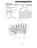
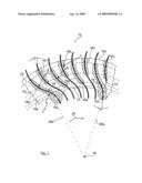
[0011]The diagrammatic drawing shows a partial cross-section through the webs of an internally ventilated brake disk for motor vehicles.
DETAILED DESCRIPTION OF THE PREFERRED EMBODIMENTS OF THE INVENTION
[0012]The drawing shows a segment of an internally ventilated brake disk 10 for motor vehicles, of which, however, essentially only one annular friction disk 12 can be seen. The second, axially adjacent friction disk. 14 is indicated diagrammatically only on the right edge of the drawing.
[0013]The two friction disks 12, 14 of the brake disk 10 are connected to one another by means of webs 16, with essentially radial cooling channels (without reference numbers) being delimited between the webs 16. The cooling channels extend in each case from the inner peripheral edge 10a to the outer peripheral edge 10b of the brake disk 10.
[0014]Also, on the inner peripheral edge 10a of the brake disk 10, fastening lugs 10c are molded on, lugs in which holes are made via which the brake disk 10 can be fastened to a wheel flange, not shown, of a wheel suspension of a motor vehicle.
[0015]The webs 16 of the brake disk 10 are distributed in a symmetrical arrangement over the entire periphery thereof. Differently designed primary webs 16a, secondary webs 16b, and tertiary webs 16c extend along a preset curve section of a web curve 17 (indicated in dots and dashes), which has here an approximately S-shaped curve geometry. In each case, the web curves 17 have an identical curve shape, and, moreover, preferably viewed in the peripheral direction, are also equidistant from one another.
[0016]The longer primary webs 16a extend, as can be seen from the drawing, along a preset curve section of the respectively associated web curve 17 up to the inner peripheral edge 10a of the brake disk 10, but they end here at a distance of approximately the primary web width in front of the outer peripheral edge 10b of the brake disk 10.
[0017]The primary webs 16a, which undergo transition into the fastening lugs 10c in each case on the inner peripheral edge 10a, also have a curvature section with a negative curvature radius r1 (curved in the direction of rotation 24) and a radial outer curvature section with a positive curvature radius r2 (curved opposite to the direction of rotation 24), which undergo-transition into one another at a point of inflection 18. The points of inflection 18 of the primary webs 16a in this case lie on a common circular path 18a of the brake disk 10 around their disk center 19.
[0018]Between each two primary webs 16a, three tertiary webs 16c and two secondary webs 16b are arranged at the same peripheral distances, with two tertiary webs 16c being directly adjacent in each case to the primary webs 16a, as can be seen.
[0019]The tertiary webs 16c extend from the outer peripheral edge 10b of the brake disk 10 radially inward and end approximately at the center of the friction disks 12, 14, whereby they extend beyond the dynamic force application radius (circular line 20 indicated in dots and dashes), however.
[0020]The shorter secondary webs 16b that are arranged in each case between the tertiary webs 16c are arranged approximately in the center of the friction disks 12, 14 and symmetrically to the circular line 20, and they end, as can be seen from the drawing, in front of the inner peripheral edge 10a and the outer peripheral edge 10bb of the brake disk 10 at a distance that roughly corresponds to their web's width. In addition, the secondary webs 16b end radially inward, for example, in the area of the circular line 18a of the points of inflection 18 of the primary webs 16b and radially outward on a circular path 22 also including the ends of the primary webs 16a.
[0021]The webs 16 preferably have essentially a uniform web's width. In addition, the secondary webs 16b and the tertiary webs 16c are embodied with the same, positive curvature radius r2, as is the case in the radial outer curvature section r2 of the primary webs 16a.
[0022]In this case, the primary webs 16a are on the inner peripheral edge 10a of the brake disk 10 and thus the radial inner web curve sections are inclined as a tangential beam 26a relative to a straight line running through the center of the circle 19 and the radial inner web curve section, such that said webs form between them an angle of between 0 and 20 degrees, in particular about 15 degrees.
[0023]Furthermore, the angle β of the radial outer tertiary web end sections of the tertiary webs 16c that are guided to the outer peripheral edge 10b of the brake disk 10 relative to a straight line that is applied through the center of the circle 19 and the radial outer tertiary web end section as a tangential beam 26b is preferably between 0 and 30 degrees, in particular about 20 degrees.
User Contributions:
comments("1"); ?> comment_form("1"); ?>Inventors list |
Agents list |
Assignees list |
List by place |
Classification tree browser |
Top 100 Inventors |
Top 100 Agents |
Top 100 Assignees |
Usenet FAQ Index |
Documents |
Other FAQs |
User Contributions:
Comment about this patent or add new information about this topic:
| People who visited this patent also read: | |
| Patent application number | Title |
|---|---|
| 20150364901 | LENS MOUNTING ARRANGEMENTS FOR HIGH-POWER LASER SYSTEMS |
| 20150364900 | STABILIZATION OF WAVELENGTH BEAM COMBINING LASER SYSTEMS IN THE NON-WAVELENGTH BEAM COMBINING DIRECTION |
| 20150364899 | BRAGG GRATING EXTERNAL CAVITY LASER |
| 20150364898 | LASER WITH SUB-WAVELENGTH HOLE ARRAY IN METAL FILM |
| 20150364897 | Discrete Raman Amplifier |
Images included with this patent application:
 |  |
| Similar patent applications: | |
| Date | Title |
|---|---|
| 2011-10-27 | Internally ventilated brake disc |
| 2010-02-04 | Brake disk for a disk brake |
| 2008-10-23 | Integrated outboard wet disk brake |
| 2009-03-05 | Ventilated brake disk and method |
| 2009-04-30 | Parking brake device of disk brake |
| New patent applications in this class: | |
| Date | Title |
|---|---|
| 2019-05-16 | Brake disc and method for producing same |
| 2018-01-25 | Brake rotor assembly and a brake rotor weight |
| 2017-08-17 | Non-woven, fracture reducing brake rotor preforms and pads |
| 2016-12-29 | Brake disk device for a vehicle |
| 2016-06-30 | Keyed brake disk assembly |
| Top Inventors for class "Brakes" | |
| Rank | Inventor's name |
|---|---|
| 1 | Johann Baumgartner |
| 2 | Robert Trimpe |
| 3 | Wayne-Ian Moore |
| 4 | Szu-Fang Tsai |
| 5 | John Marking |