Patent application title: Cargo stabilizer for storage areas in vehicles
Inventors:
Victor Lloyd Burgess (San Jose, CA, US)
IPC8 Class: AB63B2524FI
USPC Class:
410 94
Class name: Freight accommodation on freight carrier load bearer accommodation load bearer abutment
Publication date: 2009-03-26
Patent application number: 20090080993
Inventors list |
Agents list |
Assignees list |
List by place |
Classification tree browser |
Top 100 Inventors |
Top 100 Agents |
Top 100 Assignees |
Usenet FAQ Index |
Documents |
Other FAQs |
Patent application title: Cargo stabilizer for storage areas in vehicles
Inventors:
Victor Lloyd Burgess
Agents:
JAMES RAY & ASSOCIATES
Assignees:
Origin: MONROEVILLE, PA US
IPC8 Class: AB63B2524FI
USPC Class:
410 94
Abstract:
An apparatus to minimize movement of cargo disposed in a pre-selected
container during movement of a vehicle. The apparatus has a base member
having a first portion thereof positionable under such pre-selected
container and a second portion of the base member extends outwardly from
an outer edge of such pre-selected container. There is an upstanding
member disposed at a juncture of such first portion and such second
portion of the base member. Such upstanding member engages along one edge
thereof with an upper surface of such base member and adjacent a first
surface thereof with an outer surface of such pre-selected container to
provide resistance to movement of such pre-selected container during such
movement of such vehicle. An at least one gusset member engages the upper
surface of such base member and a second radially opposed surface of the
upstanding member for providing rigidity to such upstanding member.Claims:
1. An apparatus for use in a cargo area of a vehicle which will
substantially minimize movement of cargo disposed in a pre-selected
container during movement of such vehicle, said apparatus comprising:(a)
a base member having each of a first predetermined shape and a first
predetermined thickness, a first portion of said base member positionable
under such pre-selected container and a second portion of said base
member extending outwardly from an outer edge of such pre-selected
container;(b) an upstanding member, having each of a second predetermined
shape and a second predetermined thickness, disposed at a juncture of
said first portion and said second portion of said base member and
engageable along one edge thereof with an upper surface of said base
member and adjacent a first surface thereof with an outer surface of such
pre-selected container to provide resistance to movement of such
pre-selected container during such movement of such vehicle; and(c) at
least one gusset member, having each of a third predetermined shape and a
third predetermined thickness, engageable with said upper surface of said
base member and a second radially opposed surface of said upstanding
member for providing rigidity to said upstanding member.
2. An apparatus, according to claim 1, wherein said apparatus further includes a pair of gusset members.
3. An apparatus, according to claim 2, wherein a predetermined shape of each of said gusset members is substantially identical.
4. An apparatus, according to claim 3, wherein said third predetermined shape is generally triangular.
5. An apparatus, according to claim 1, wherein said first predetermined shape is T-shaped.
6. An apparatus, according to claim 1, wherein said second predetermined shape is generally rectangular.
7. An apparatus, according to claim 6, wherein said upstanding member includes a centrally located opening disposed there through.
8. An apparatus, according to claim 1, wherein said apparatus further includes a predetermined plurality of feet like members disposed on a bottom surface of said base member for gripping into a surface disposed in such cargo area of such vehicle.
9. An apparatus, according to claim 8, wherein each of said predetermined plurality of feet have a predetermined shape which allows easy sliding in a first direction and resists sliding in an axially opposed direction.
10. An apparatus, according to claim 1, wherein said upstanding member is hingedly connected to said base member.
11. An apparatus, according to claim 10, wherein said at least one gusset member is hingedly connected to said upstanding member to enable said apparatus to be folded flat for storage when not in use.
12. An apparatus, according to claim 1, wherein each of said first, said second, and said third predetermined thickness are substantially identical.
13. An apparatus, according to claim 12, wherein each of said first, said second, and said third predetermined thickness is generally between about one-sixteenth and about three thirty seconds of an inch.
14. In combination with a cargo area of a pre-selected vehicle, the improvement comprising an apparatus for use in said cargo area of said pre-selected vehicle which will substantially minimize movement of cargo disposed in a pre-selected container during movement of said vehicle which apparatus includes:(a) a base member having each of a first predetermined shape and a first predetermined thickness, a first portion of said base member positionable under such pre-selected container and a second portion of said base member extending outwardly from an outer edge of such pre-selected container;(b) an upstanding member, having each of a second predetermined shape and a second predetermined thickness, disposed at a juncture of said first portion and said second portion of said base member and engageable along one edge thereof with an upper surface of said base member and adjacent a first surface thereof with an outer surface of such pre-selected container to provide resistance to movement of such pre-selected container during such movement of said pre-selected vehicle; and(c) at least one gusset member, having each of a third predetermined shape and a third predetermined thickness, engageable with said upper surface of said base member and a second radially opposed surface of said upstanding member for providing rigidity to said upstanding member.
15. The combination, according to claim 14, wherein said pre-selected vehicle is selected from the group consisting of vans, mini-vans, trucks and cars.
16. The combination, according to claim 14, wherein said apparatus is constructed from metal for use with heavy cargo.
17. The combination, according to claim 14, wherein said metal is selected from one of aluminum and steel having a pre-selected coating disposed thereon to prevent rusting.
18. The combination, according to claim 14, wherein said apparatus is constructed from plastic for use with light cargo.
Description:
FIELD OF THE INVENTION
[0001]The present invention relates, in general, to devices for securing cargo in vehicles and, more particularly, this invention relates to a freestanding device for use in the storage areas of such vehicles.
BACKGROUND OF THE INVENTION
[0002]Cargo is transported in vans, mini-vans, trucks and cars on a daily basis. When operating a vehicle unsupported cargo can fall over, shift, and possibly break. If cargo is being transported in the passenger area of a vehicle and an unsupported article rolls up to the driver side and lodges under a gas or brake pedal this could create a hazardous condition.
[0003]Various devices have been designed for securing cargo in the storage areas of vehicles but they typically occupy an entire trunk or bed area, are bulky, and either need to be fixed or rely on their mass in order to keep the entire assembly from shifting or falling over. These devices typically include adjustable compartments that require a great deal of effort in order to arrange a space to accommodate a specifically sized and/or shaped object. Existing art designs require removal prior to placing routinely transported large cargo items and in addition they have to be remotely stored which typically occupies a large area in ones home or business.
SUMMARY OF THE INVENTION
[0004]An apparatus for use in a cargo area of a vehicle that will substantially minimize movement of cargo disposed in a pre-selected container during movement of such vehicle. The apparatus includes a base member having each of a first predetermined shape and a first predetermined thickness. A first portion of the base member is positioned under such pre-selected container and a second portion of such base member extends outwardly from an outer edge of such pre-selected container. There is an upstanding member, having each of a second predetermined shape and a second predetermined thickness, disposed at a juncture of such first portion and such second portion of the base member. The upstanding member engages along one edge thereof with an upper surface of such base member and adjacent a first surface thereof with an outer surface of such pre-selected container to provide resistance to movement of such pre-selected container during such movement of such vehicle. Further, there is at least one gusset member, having each of a third predetermined shape and a third predetermined thickness, engageable with such upper surface of the base member and a second radially opposed surface of such upstanding member for providing rigidity to the upstanding member.
[0005]In a second aspect of the invention, such apparatus is provided in combination with a cargo area of a pre-selected vehicle.
OBJECTS OF THE INVENTION
[0006]It is, therefore, one of the primary objects of the present invention to provide a quick and easy freestanding cargo stabilizer for securing cargo in vehicle storage areas.
[0007]Another object of the present invention is to provide a cargo stabilizer that includes directional feet that allow the unit to be easily slid under a cargo item.
[0008]Still another object of the present invention is to provide a cargo stabilizer that includes directional feet that maintain the position of a cargo item during transport.
[0009]Yet another object of the present invention is to provide a cargo stabilizer that is designed so that cargo sits flush against the product maintaining the item in a vertical position.
[0010]An additional object of the present invention is to provide a cargo stabilizer that requires no installation.
[0011]Still another object of the present invention is to provide a cargo stabilizer where the lower portion can be adjusted to an appropriate length in order to accommodate various sized items.
[0012]Yet another object of the present invention is to provide a cargo stabilizer that can be folded flat when not in use.
[0013]An additional object of the present invention is to provide a cargo stabilizer that can be manufactured in various sizes.
[0014]Still a further object of the present invention is to provide a cargo stabilizer that is made of strong and durable material.
[0015]Yet another object of the present invention is to provide a cargo stabilizer that enables the user to position cargo in any location in a vehicle storage area.
[0016]In addition to the various objects and advantages of the present invention described with some degree of specificity above, it should be obvious that additional objects and advantages of the present invention will become more readily apparent to those persons who are skilled in the relevant art from the following more detailed description of the invention, particularly, when such description is taken in conjunction with the attached drawing figures and with the appended claims.
BRIEF DESCRIPTION OF THE DRAWINGS
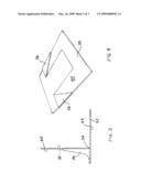
[0017]FIG. 1 is a perspective view of one presently preferred embodiment of the invention shown in an upright position.
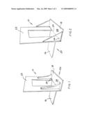
[0018]FIG. 2 is a perspective view of an alternative embodiment of the invention illustrated in FIG. 1 and also shown in an upright position.
[0019]FIG. 3 is a side elevation view of the invention shown in FIG. 1.
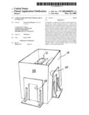
[0020]FIG. 4 is a perspective view of the invention shown in FIG. 2 illustrated in a folded position.
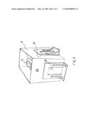
[0021]FIG. 5 is a perspective view showing the cargo stabilizer of the present invention in use.
DETAILED DESCRIPTION OF A PRESENTLY PREFERRED AND VARIOUS ALTERNATIVE EMBODIMENTS OF THE INVENTION
[0022]Prior to proceeding to the more detailed description of the present invention it should be noted that, for the sake of clarity and understanding, identical components which have identical functions have been identified with identical reference numerals throughout the several views illustrated in the drawing figures.
[0023]Additionally, as used in the present specification the term vehicle is meant to include each of trucks, autos, mini-vans, buses, railway vehicles and airplanes.
[0024]Now refer, more particularly, to FIGS. 1-5. Illustrated therein is an apparatus, generally designated 10, for use in a cargo area (not shown) of a vehicle (not shown) which will substantially minimize movement of cargo 12 disposed in a pre-selected container 14 during movement of such vehicle. Although not limited thereto or thereby container 14 may be, for example, any one of a grocery bag, box or suitcase.
[0025]The apparatus 10 includes a base member, generally designated 20, having a first predetermined shape, which in the presently preferred embodiment is substantially T-shaped. Base member 20 will also have a first predetermined thickness. A first portion 16 of such base member 20 is positionable under such pre-selected container 14 and a second portion 18 of the base member 20 extends in an outwardly direction from an outer edge of such pre-selected container 14.
[0026]There is an upstanding member 22, having a second predetermined shape, which in the presently preferred embodiment of the invention is generally rectangular. Additionally, upstanding member 22 will have a second predetermined thickness which is substantially identical to the predetermined thickness of the base member 20. Upstanding member 22 is disposed at a juncture 24 of such first portion 16 and such second portion 18 of the base member 20 and is engageable along one edge 26 thereof with an upper surface 28 of the base member 20 and adjacent a first surface 30 thereof with an outer surface 32 of such pre-selected container 14 to provide resistance to movement of pre-selected container 14 during movement of such vehicle.
[0027]In the presently preferred embodiment of the invention, the upstanding member 22 and the base member 20 of the apparatus 10 are formed as a stamping as a single piece of generally rectangular material having each of a predetermined length and a predetermined width. Nevertheless in the presently preferred embodiment the upstanding member 22 is hingedly connected to the base member 20 by a hinge member 34 so that the apparatus 10 may be folded substantially flat for storage when it is not in use. When the upstanding member 22 and the base member 20 are formed from a single piece there is an aperture formed in upstanding member 22.
[0028]Further, there is at least one gusset member 36 and preferably a pair of gusset members 36, having each of a third predetermined shape and a third predetermined thickness, engageable with such upper surface 28 of the base member 20. Gusset members 36 are preferable hingedly connected to a second radially opposed surface 40 of the upstanding member 22 for providing rigidity to upstanding member 22. Preferably, each one of the pair of gussets will have a substantially identical shape. Such shape is preferably generally triangular.
[0029]As best seen in FIG. 3, the apparatus 10, in the presently preferred embodiment of the invention, will include a predetermined plurality of feet like members 42 disposed on a bottom surface 44 of the base member 20 for gripping into a surface disposed in such cargo area of such vehicle. Such predetermined plurality of feet like members 42 have a predetermined shape which allows easy sliding in a first direction and resists sliding in an axially opposed direction.
[0030]In the presently preferred embodiment of the invention, each of first, second, and third predetermined thicknesses are substantially identical and will fall within a range of generally between about one-sixteenth and about three thirty seconds of an inch.
[0031]According to the invention such pre-selected vehicle is selected from the group consisting of vans, mini-vans, trucks, cars, railway cars and airplanes. Additionally, apparatus 10 is constructed from metal which is coated to prevent corrosion for use with heavy cargo. Apparatus 10 may be manufactured from plastic for use with light cargo.
[0032]While a presently preferred and various alternative embodiments of the present invention have been described in sufficient detail above to enable a person skilled in the relevant art to make and use the same, it should be obvious that various other adaptations and modifications can be envisioned by those persons skilled in such art without departing from either the spirit of the invention or the scope of the appended claims.
User Contributions:
comments("1"); ?> comment_form("1"); ?>Inventors list |
Agents list |
Assignees list |
List by place |
Classification tree browser |
Top 100 Inventors |
Top 100 Agents |
Top 100 Assignees |
Usenet FAQ Index |
Documents |
Other FAQs |
User Contributions:
Comment about this patent or add new information about this topic:
| People who visited this patent also read: | |
| Patent application number | Title |
|---|---|
| 20220284859 | DISPLAY DEVICE |
| 20220284858 | DISPLAY DRIVING DEVICE AND METHOD WITH LOW POWER CONSUMPTION |
| 20220284857 | DISPLAY DEVICE AND MANUFACTURING METHOD THEREOF |
| 20220284856 | DISPLAY PANEL AND DISPLAY DEVICE |
| 20220284855 | DISPLAY DEVICE AND DRIVING METHOD OF THE SAME |
Images included with this patent application:
 |  |
 |  |
| Similar patent applications: | |
| Date | Title |
|---|---|
| 2013-10-03 | Attenuating cargo restraint device |
| 2010-11-18 | Stowable storage net |
| 2013-11-21 | Repositionable trailer tie-down bracket |
| 2013-12-26 | Cargo securing device |
| 2009-12-03 | Restraint chain storage |
| New patent applications in this class: | |
| Date | Title |
|---|---|
| 2014-12-18 | End stop device, cargo loading system and aircraft |
| 2012-03-29 | Collapsible intermodal transport platform |
| 2011-02-03 | Dunnage holder |
| 2011-01-06 | Air cargo rollout stop |
| 2008-12-04 | Vehicle cargo bed |
| Top Inventors for class "Freight accommodation on freight carrier" | |
| Rank | Inventor's name |
|---|---|
| 1 | John D. Anderson |
| 2 | Walter J. Peach |
| 3 | Michael K. Burke |
| 4 | Jerrell P. Squyres |
| 5 | Jean-Marc Girardin |