Patent application title: COLLAPSIBLE, PORTABLE PUPPET STAGE
Inventors:
Carolyn T. Frank (Kaysville, UT, US)
Gregory A. Frank (Kaysville, UT, US)
IPC8 Class: AA63J1900FI
USPC Class:
446 82
Class name: Amusement devices: toys toy theater
Publication date: 2009-03-19
Patent application number: 20090075552
Inventors list |
Agents list |
Assignees list |
List by place |
Classification tree browser |
Top 100 Inventors |
Top 100 Agents |
Top 100 Assignees |
Usenet FAQ Index |
Documents |
Other FAQs |
Patent application title: COLLAPSIBLE, PORTABLE PUPPET STAGE
Inventors:
Carolyn T. Frank
Gregory A. Frank
Agents:
PATE PIERCE & BAIRD
Assignees:
Origin: SALT LAKE CITY, UT US
IPC8 Class: AA63J1900FI
USPC Class:
446 82
Abstract:
A method comprising identifying a frame comprising a plurality of rods
forming a plurality of rod pairs or rod scissors, deploying the frame to
create a structure comprising a base, stage right support, and stage left
support, applying a cover to the frame, and suspending a curtain between
the stage right and stage left supports to form a backdrop and upstage
boundary for the stage.Claims:
1. A method comprising:identifying a frame comprisinga plurality of rods
forming a plurality of rod pairs, each rod of the plurality of rods
comprising a midpoint and being pivotably connected proximate the
midpoint to another rod of the plurality of rods to form a rod pair of
the plurality of rod pairs, anda plurality of hubs, each hub of the
plurality of hubs connecting a rod pair of the plurality of rod pairs to
an adjacent rod pair of the plurality of rod pairs;deploying the frame to
create a structure comprising a base, stage right support, and stage left
support, the stage right support and stage left support connected to the
base to extend upward therefrom and frame therewith a right side, left
side, and floor, respectively, of a stage;applying a cover to the frame;
andsuspending a curtain between the stage right and stage left supports
to form a backdrop and upstage boundary for the stage.
2. The method of claim 1, wherein deploying comprises converting the frame from a collapsed form to an expanded form.
3. The method of claim 2, wherein the frame is characterized by a thickness, lateral span, and vertical height and wherein the thickness decreases, and the lateral span and vertical height increase, during the converting from the collapsed form to the expanded form.
4. The method of claim 3, wherein deploying further comprises urging a decrease in the thickness and ensuring clearance for increases in the lateral span and vertical height.
5. The method of claim 4, wherein deploying further comprises locking the frame in the expanded form to maintain the structure erect against the acceleration of gravity acting thereon.
6. The method of claim 5, wherein locking comprises effecting a mechanical link between one hub of the plurality of hubs and another hub of the plurality of hubs, the mechanical link opposing a separation, of the one hub from the other hub, urged by the acceleration of gravity acting on the structure.
7. The method of claim 6, further comprising positioning a platform on the base to form the floor of the stage.
8. The method of claim 7, wherein the cover is opaque.
9. The method of claim 8, wherein applying the cover comprises securing the cover to selected hubs of the plurality of hubs.
10. The method of claim 9, wherein the selected hubs are equipped with a hook material.
11. The method of claim 10, wherein the cover comprises a fabric having fibers.
12. The method of claim 11, wherein applying the cover comprises urging engagement between the hook material and the fibers.
13. The method of claim 12, wherein the frame further comprises a right curtain support, a left curtain support, and a curtain rod.
14. The method of claim 13, wherein the curtain rod is selectively collapsible.
15. The method of claim 14, wherein suspending the curtain comprises assembling the curtain rod.
16. The method of claim 15, wherein suspending the curtain further comprises securing a first end of the curtain rod to the right curtain support and a second end of the curtain rod to the left curtain support.
17. The method of claim 16, wherein the right curtain support is connected to the structure proximate the top of the stage right support and the left curtain support is connected to the structure proximate the top of the stage left support.
18. The method of claim 17, wherein the curtain is semitransparent and suspending the curtain further comprises threading the curtain onto the curtain rod.
19. A method comprising:identifying a frame comprisinga plurality of rods forming a plurality of rod pairs, each rod of the plurality of rods comprising a midpoint and being pivotably connected proximate the midpoint to another rod of the plurality of rods to form a rod pair of the plurality of rod pairs, anda plurality of hubs, each hub of the plurality of hubs connecting a rod pair of the plurality of rod pairs to an adjacent rod pair of the plurality of rod pairs;deploying the frame to create a structure comprising a base, stage right support, and stage left support, the stage right support and stage left support connected to the base to extend upward therefrom and frame therewith a right side, left side, and floor, respectively, of a stage;applying an opaque cover to the frame to resist visibility through the base, stage right support, and stage left support;positioning a platform on the base to form the floor of the stage;suspending a semitransparent curtain between the stage right and stage left supports to form a backdrop and upstage boundary for the stage;standing a performer behind the curtain;positioning an audience in front of the curtain; andperforming, by the performer while standing, a puppet presentation on the stage.
20. A method comprising:identifying a frame characterized by a thickness, lateral span, and vertical height, the frame comprisinga plurality of rods forming a plurality of rod pairs, each rod of the plurality of rods comprising a midpoint and being pivotably connected proximate the midpoint to another rod of the plurality of rods to form a rod pair of the plurality of rod pairs,a plurality of hubs, each hub of the plurality of hubs connecting a rod pair of the plurality of rod pairs to an adjacent rod pair of the plurality of rod pairs, anda lock;converting the frame from a collapsed form to an expanded form by urging at least one of a decrease in the thickness, an increase in the lateral span, and an increase in the vertical height, the frame in the expanded form creating a structure comprising a base, stage right support, and stage left support, the stage right support and stage left support connected to the base to extend upward therefrom and frame therewith a stage right, stage left, and floor, respectively, of a stage;using the lock to effect a mechanical link between one hub of the plurality of hubs and another hub of the plurality of hubs, the mechanical link opposing a separation, of the one hub from the other hub, urged by the acceleration of gravity acting on the structure.applying an opaque cover to the frame to resist visibility through the base, stage right support, and stage left support;positioning a platform on the base to form the floor of the stage;suspending a curtain between the stage right and stage left supports to form a backdrop and upstage boundary for the stage;standing a performer behind the curtain;positioning an audience in front of the curtain; andperforming, by the performer while standing, a puppet presentation on the stage.
Description:
RELATED APPLICATIONS
[0001]This application claims the benefit of co-pending U.S. Provisional Patent Application Ser. No. 60/973,234 filed Sep. 18, 2007.
BACKGROUND
[0002]1. The Field of the Invention
[0003]This invention relates to puppet stages and, more particularly, to novel systems and methods for a puppet stage that is convenient to store, transport, setup, and take down.
[0004]2. The Background Art
[0005]Various puppet stages have been developed. However, typical free standing, portable stages are too small to adequately conceal puppeteers. Accordingly, puppeteers must kneel or sit behind the stages to conceal themselves. Alternatively, puppeteers must place the portable stage on a table to achieve an appropriate height to present a puppet show. Typical puppet stages designed with sufficient size to conceal puppeteers are not portable or are heavy and difficult to store, transport, setup, and take down. Accordingly, what is needed is a puppet stage offering convenient portability with a size sufficient to conceal one or more puppeteers.
BRIEF SUMMARY OF THE INVENTION
[0006]In view of the foregoing, in accordance with the invention as embodied and broadly described herein, a method and apparatus are disclosed in one embodiment of the present invention as including a collapsible puppet stage. In selected embodiments, a puppet stage in accordance with the present invention may include a frame comprising a plurality of rods forming a plurality of rod pairs. Each rod may include a midpoint and be pivotably connected proximate that midpoint to another rod. Accordingly, in certain embodiments, each rod may form part (e.g., one half) of a rod pair or rod scissor.
[0007]A frame may also include a plurality of hubs. Each hub may pivotably connect a rod pair to an adjacent rod pair. In a deployed configuration, a frame may form a structure having a base, stage right support, and stage left support. The stage right support and stage left support may be connected to the base to extend upward therefrom. The stage right and left supports may cooperate with the base to form a right side, left side, and floor, respectively, of the stage.
[0008]In selected embodiments, deploying a frame in accordance with the present invention includes converting the frame from a collapsed form to an expanded form. For example, a frame may be characterized by a thickness, lateral span, and vertical height. When converting the frame from the collapsed form to the expanded form, the thickness may decrease, while the lateral span and vertical height may increase. To assist in deploying a frame, a user may urge a decrease in the thickness, while ensuring that there is sufficient clearance for increases in the lateral span and vertical height.
[0009]A frame may include a lock. A lock may secure the frame in the expanded form, erect against the acceleration of gravity acting thereon. In selected embodiments, a lock may comprise a mechanical link between two hubs. The mechanical link may oppose a separation of one hub from the other. Once secured in the expanded form, a platform or play board may be positioned on the frame to form the floor of the performance area.
[0010]A cover may be applied to the frame to block visibility therethrough (e.g., the cover may be opaque). In selected embodiments, a cover may be formed of a fabric having fibers. Applying the cover to the frame may include securing the cover to the selected hub. The selected hubs may be equipped with a hook material engaging and holding the fibers of the cover.
[0011]A curtain may be suspended between the stage right and stage left supports to form a backdrop and upstage boundary for the stage or performance area. For example, a frame may include a right curtain support, a left curtain support, and a curtain rod. In selected embodiments, the curtain rod may be selectively collapsible. Once the curtain rod is assembled, a curtain may be suspended therefrom. For example, the curtain may be threaded onto the curtain rod to form a curtain assembly.
[0012]A curtain assembly may be secured to a frame in any suitable manner. In selected embodiments, a first end of the curtain rod may be secured to the right curtain support and a second end of the curtain rod may be secured to the left curtain support. In certain embodiments, the right curtain support may be connected to the rest of the frame proximate the top of the stage right support. The left curtain support may be connected to the rest of the frame proximate the top of the stage left support. In one embodiment, the curtain may be formed of a material that is semitransparent.
[0013]In selected embodiments, a method in accordance with the present invention may include: (1) identifying a frame; (2) deploying the frame to create a structure comprising a base, stage right support, and stage left support; (3) using a lock to secure the frame in the deployed form; (4) applying an opaque cover to the frame to resist visibility through the base, stage right support, and stage left support; (5) positioning a platform on the base to form the floor of the stage or performance area; (6) suspending a semitransparent curtain between the stage right and stage left supports to form a backdrop and upstage boundary for the stage; (7) standing a performer behind the curtain; (8) positioning an audience in front of the curtain; and (9) performing, by the performer while standing, a puppet presentation on the stage or performance area.
BRIEF DESCRIPTION OF THE DRAWINGS
[0014]The foregoing features of the present invention will become more fully apparent from the following description and appended claims, taken in conjunction with the accompanying drawings. Understanding that these drawings depict only typical embodiments of the invention and are, therefore, not to be considered limiting of its scope, the invention will be described with additional specificity and detail through use of the accompanying drawings in which:
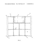
[0015]FIG. 1 is a front elevation view of one embodiment of a collapsible puppet stage in accordance with the present invention in a fully deployed form;
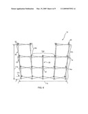
[0016]FIG. 2 is a rear elevation view of the collapsible puppet stage of FIG. 1;
[0017]FIG. 3 is a perspective view of one embodiment of a frame in accordance with the present invention in a collapsed form or position;
[0018]FIG. 4 is a perspective view of a the frame of FIG. 3 transitioning toward a deployed form or position;
[0019]FIG. 5 is a perspective view of the frame of FIG. 3 transitioning further toward a deployed form or position;
[0020]FIG. 6 is a perspective view of the frame of FIG. 3 in the deployed form or position;
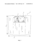
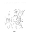
[0021]FIG. 7 is a partial perspective view of one embodiment of a frame in accordance with the present invention having a lock securing the frame in the deployed form or position;
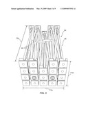
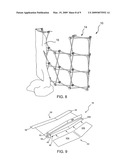
[0022]FIG. 8 is a perspective view of a one embodiment of a cover being applied to a deployed frame in accordance with the present invention;
[0023]FIG. 9 is a perspective view of a play board insert being inserted within a play board cover to form one embodiment of a play board in accordance with the present invention;
[0024]FIG. 10 is a partial perspective view of one embodiment of a frame in accordance with the present invention having a curtain rod support; and
[0025]FIG. 11 is a partial perspective view of one embodiment of a curtain rod assembly applied to a frame in accordance with the present invention.
DETAILED DESCRIPTION OF SELECTED EMBODIMENTS
[0026]It will be readily understood that the components of the present invention, as generally described and illustrated in the drawings herein, could be arranged and designed in a wide variety of different configurations. Thus, the following more detailed description of the embodiments of the system and method of the present invention, as represented in the drawings, is not intended to limit the scope of the invention, as claimed, but is merely representative of various embodiments of the invention. The illustrated embodiments of the invention will be best understood by reference to the drawings, wherein like parts are designated by like numerals throughout.
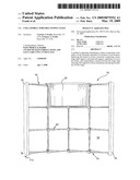
[0027]Referring to FIGS. 1 and 2, in selected embodiments, an apparatus 10 in accordance with the present invention may provide a lightweight puppet stage 10 designed to expand from a compact form into a full size stage. The stage 10 may include a height 11a, width 11b, and thickness 11c sufficient for one or more puppeteers to easily work alone or together to perform puppet plays. Thus, a stage 10 in accordance with the present invention may be suitable for puppets 12 (e.g., marionettes, hand puppets, ventriloquist dolls typically worn on puppeteer arms and hands, and the like). A stage 10 may also accommodate large stick puppets 12 and glove finger puppets 12.
[0028]In selected embodiments, a puppet stage 10 in accordance with the present invention may include four major assemblies, namely, the frame 14, cover 16, play board 18, and curtain 20. The frame 14 may include a network of rods 22 formed of any suitable material. Suitable materials may include metal, wood, plastic, fiberglass, composite materials, and the like.
[0029]Selected components of a stage 10 may define the structures and boundaries for a performance area 21. In selected embodiments, the performance area 21 may be bounded by a stage right 21a, stage left 21b, down stage 21c, and up stage 21d. In one embodiment, the forward edge of a play board 18 may define the maximum extent of down stage 21c, while the curtain 20 may define the maximum extent of up stage 21d.
[0030]In certain embodiments, a stage 10 in accordance with the present invention may extend arcuately across a supporting floor. The arcuate shape may be defined by the frame 14. In selected embodiments, the arcuate shape may improve the screening effect of the stage 10. That is, the arcuate shape may tend to enclose performers located behind the stage. Additionally, the arcuate shape may increase the stability of the stage 10, decreasing the ease with which the stage 10 may be tipped over.
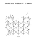
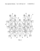
[0031]Referring to FIGS. 3-6, the geometry of the rods 22 may be such that the frame 14 may collapse into a compact form 24 for storage and transport and expand to a fully deployed form 26 defining the structure for a puppet stage 10 in accordance with the present invention. The number of rods 22 used may vary. More rods 22 may be used to provide more load bearing capacity and sturdiness while fewer rods 22 provide a lightweight option.
[0032]In certain embodiments, a base component of the frame 14 may be a rod pair 28 or rod scissor 28 comprising two rods 22 connected together by a pivot 30 (e.g., pin or rivet) proximate a midpoint of each rod 22. In selected embodiments, placement of the pivot 30 may control the arcuate shape of the frame 14. That is, placing the pivot 30 slightly off the midpoint of the rods 22 may cause a differential in expansion of the rod scissor 28, providing a desired arcuate shape.
[0033]Rod scissors 28 may be connected together with hubs 32 to form the complete frame 14. The hubs 32 may be formed of any suitable material. Suitable materials may include metal, wood, plastic, fiberglass, composite materials, and the like. Through the connecting hubs 32, collapse or expansion of one rod scissor 28 may cause collapse or expansion of adjacent rod scissors 28. Accordingly, expansion and collapse of the frame 14 may proceed substantially uniformly throughout the various rod scissors 28.
[0034]Referring to FIG. 6, in a deployed form 26, a frame 14 may create a structure comprising a base 14a, stage right support 14b, and stage left support 14c. The stage right support 14b may connect to the base 14a to extend upward therefrom and form a right side of the performance area 21. The stage left support 14c may connect to the base 14a and extend upward therefrom to form the left side of the performance area 21. In selected embodiments, the curtain 20 may be suspended between the stage right and stage left supports 14b, 14c to form a backdrop and upstage boundary 21d for the performance area 21. The top portion 14d of the base 14a located between the stage right support 14b and the stage left support 14c may form the structure supporting the play board 18.
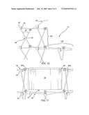
[0035]Referring to FIG. 7, once fully expanded, a lock 34 may secure the frame 14 in place. In selected embodiments, the lock 34 may oppose the accelerations of gravity acting on the structures 14, 16, 18, 20 of the stage 10 that urge a return of the frame 14 to a collapsed state. In selected embodiments, a lock 34 may comprise a mechanical linkage between opposing hubs 32a, 32b. The lock 34 may resist separation of the hubs 32a, 32b. For example, in one embodiment, a lock 34 may be formed by a hook 36 extending from a first hub 32a to engage an eye bolt 38 extending from a second hub 32b. Alternatively, a lock 34 may comprise a plug ( e.g., male connector) extending from one hub 32a, 32b to engage a corresponding receptacle (e.g., female connector) extending from an opposing hub 32b, 32a.
[0036]In certain embodiments, a frame 14 may include more than one lock 34. The number and placement of the locks 34 may be determined to satisfy the structural demands imposed by the size and shape of the frame 14. In one embodiment, a frame 14 may include two locks 34. A first lock 34 may be positioned within the frame 14 at a location one rod scissor 28 above a floor supporting the frame 14 and one rod scissor 28 in from one side of the frame 14. A second lock 34 may be positioned within the frame 14 at a location one rod scissor 28 above the floor and one rod scissor 28 in from the other side of the frame 14.
[0037]In selected embodiments, certain perimeter hubs 32 located on the front side and ends of the frame 14 may include an outward facing surface 40 having an attachment mechanism applied thereto. An attachment mechanism may facilitate securement of the cover 16 to the frame 14. For example, in one embodiment, a patch of hook-and-loop type fastening material may be applied to the outward facing surfaces 40 of certain hubs 32.
[0038]Referring to FIG. 8, a cover 16 in accordance with the present invention provide a visual barrier between an audience and a puppeteer. A cover 16 may be held in place and supported by the frame 14. A cover 16 may be formed of any suitable material. In selected embodiments, a cover 16 may be formed of a fabric material. In one embodiment, a cover 16 may be formed of a fabric compatible with hook-and-loop type materials. For example, one or both sides of the fabric forming the cover 16 may support engagement with the hooks of a hook-and-loop type fastener. In such an embodiment, the loops of the hook-and-loop type fastener need not be applied to the cover 16. That is, for example, the cover 16 may adhere directly to hook material applied to the outward facing surfaces 40 of selected hubs 32.
[0039]Alternatively, in embodiments where the backside of the cover 16 may not be compatible with the hooks of a hook-and-loop type fastener, suitable loop patches must be placed on the back side of the cover 16. The loop patches may engage hook material applied to the outward facing surfaces 40 of selected hubs 32. In selected embodiments, the loop patches must be sewn at specific locations on the back side of the cover 16. Those locations may be selected based on the location of the hubs 32 on the frame 14 that may be equipped with corresponding hook patches. Accordingly, a cover 16 may be applied to a frame by matching patches on the cover with patches of the frame 14 in a step-by-step process.
[0040]Referring to FIG. 9, in selected embodiments, a frame 14 may define a performance area 21. In certain embodiments, a play board 18 may be positioned on a portion of the base frame 14a to form the floor of the performance area 21. A play board 18 may be secured to the frame 14 and accommodate the presentation of puppets and props in a puppet play. A play board 18 may be formed of any suitable material or combination of materials. Suitable materials may include fabric, plastic, wood, cardboard, and the like.
[0041]In certain embodiments, a play board 18 may include two major components, namely, an insert 42 and a play board cover 44. An insert 42 may provide some rigidity and structure, while the play board cover 44 may provide a particular look (e.g., a look matching the cover 16 or curtain 20). In selected embodiments, an insert 42 may comprise one or more pieces (e.g., two mirror image pieces 42a, 42b) for ease of storage, transportation, and insertion into the play board cover 44. In selected embodiments, a play board cover 44 may be formed of the same fabric (e.g., hook-and-loop compatible fabric) as the cover 16 for the frame 14.
[0042]In selected embodiments, the front edge 46 of the play board cover 44 may include an opening 48 for insertion of an insert 42. In one embodiment, the sides 50a, 50b of the opening 48 may be lined with opposing hook-and-loop strips to capture an insert 42 within the play board cover 44. Alternatively, when a compatible cover material is used, one side 50a of the opening 48 may include a hook type material suitable to engage the other side 50b. In certain embodiments, one side 50a (e.g., the "hook" side) may have a width 52 greater than the width 54 of the other side 50b. Accordingly, one side 50a may extend past the other 50b and engage the cover 16 extending on the front surface of the stage 16.
[0043]In selected embodiments, hook-and-loop patches 56 or tabs 56 may be located at or extend from the rear corners of a play board cover 44. These tabs 56 may be used to attach the play board 18 to the frame 14. In certain embodiments, there may be also a hook-and-loop patch secured to the middle back edge 58 of the play board cover 44 to secure to a hub 32 having a corresponding hook-and-loop patch.
[0044]Referring to FIGS. 10 and 11, in selected embodiments, a curtain rod hook 60a, 60b may be located at the top of the stage right and left supports 14b, 14c, respectively. Each hook 60 may be pivotably connected at one end to a hub 32. The other end of each hook 60 may change direction (e.g., ninety degrees, one hundred ten degrees, or the like) inward toward the performance or stage area 21. A curtain rod 62 may connect to each hook 60a, 60b to extend therebetween. The curtain rod 62 may support the curtain 20.
[0045]In selected embodiments, a curtain rod 62 may include multiple (e.g., three) segments that connect together. The segmented rod 62 may be designed for easy storage and transport. Once the curtain rod 62 is assembled, the curtain 20 may be placed onto the rod before it is connected to the frame 14. In certain embodiments, a curtain 20 may be formed of a semi-transparent fabric, permitting a puppeteer to see the puppets on stage, yet hide the puppeteer from the audience. In selected embodiments, lighting in the area of the stage 10 may be arranged to enhance the effect of the curtain. That is, the primary light may be positioned on the audience side of the stage 10 and minimal or no light may be present behind the stage 10. With the curtain 20 installed on the curtain rod 62, the rod 62 may be attached to the frame 62 via the rod hooks 60a, 60b.
[0046]In certain embodiments, hooks 60a, 60b may be extendable. For example, a hook 60 may be extendable in a direction corresponding to the width 11c of a stage 10. Accordingly, the upstage 21d boundary defined by the curtain 20 may be adjustable. Extension of the hooks 60 may increase the distance between the downstage boundary 21c and the curtain 20 extending across the back of the performance area 21. Retraction of the hooks 60 may decrease the distance between the downstage boundary 21c and the curtain 20 extending across the back of the performance area 21.
[0047]In selected embodiments, a hook 60 may include multiple elements (e.g., tubes). One element or tube may slide within another element or tube to effect the extension of the hook 60. In certain embodiments, a curtain 20 in accordance with the present invention may extend from a curtain rod 62 to cover, and be suspended from, a portion of a hook 60. Accordingly, when the hooks 60 are extended, the curtain 20 may create a continuous visual barrier from a stage right support 14b rearward the full extent of a hook 60a, around the hook 60a, across the rear boundary of the performance area 21, around the other hook 60b, and forward to the stage left support 14c. A curtain 20 suspended in such a manner may obscure or block substantially all horizontal visual access through the performance area 21, even when the hooks 60a, 60b are fully extended.
[0048]The present invention may be embodied in other specific forms without departing from its spirit or essential characteristics. The described embodiments are to be considered in all respects only as illustrative, and not restrictive. The scope of the invention is, therefore, indicated by the appended claims, rather than by the foregoing description. All changes which come within the meaning and range of equivalency of the claims are to be embraced within their scope.
User Contributions:
comments("1"); ?> comment_form("1"); ?>Inventors list |
Agents list |
Assignees list |
List by place |
Classification tree browser |
Top 100 Inventors |
Top 100 Agents |
Top 100 Assignees |
Usenet FAQ Index |
Documents |
Other FAQs |
User Contributions:
Comment about this patent or add new information about this topic:
Images included with this patent application:
 |  |
 |  |
 |  |
 |  |
 |  |
| Similar patent applications: | |
| Date | Title |
|---|---|
| 2013-03-14 | Collapsible play gym |
| 2014-07-17 | Toy laser gun and laser target system |
| 2010-06-03 | Self-supporting puppet |
| 2013-08-22 | Personalized finger puppet |
| New patent applications in this class: | |
| Date | Title |
|---|---|
| 2015-05-21 | Play set for launching an action figurine |
| 2015-05-21 | Play set for launching an action figurine |
| 2012-08-16 | Toy ring stage |
| 2012-04-12 | Modular display systems |
| 2012-03-15 | Child's story themed play structure |
| Top Inventors for class "Amusement devices: toys" | |
| Rank | Inventor's name |
|---|---|
| 1 | Robert H. Mimlitch, Iii |
| 2 | David Anthony Norman |
| 3 | Michael Nuttall |
| 4 | Stacy Lynn O'Connor |
| 5 | Joel Reagan Carter |