Patent application title: BOILER PRODUCING STEAM FROM FLUE GASES WITH HIGH ELECTRICAL EFFICIENCY AND IMPROVED SLAG QUALITY
Inventors:
Kim Allan Dam-Johansen (Frederiksvaerk, DK)
Peter Arendt Jensen (Kobenhavn, DK)
Flemming J. Frandsen (Havdrup, DK)
Ole Hedegaard Madsen (Naerum, DK)
IPC8 Class: AF23G546FI
USPC Class:
122 2
Class name: Liquid heaters and vaporizers plants garbage
Publication date: 2009-02-26
Patent application number: 20090050076
Inventors list |
Agents list |
Assignees list |
List by place |
Classification tree browser |
Top 100 Inventors |
Top 100 Agents |
Top 100 Assignees |
Usenet FAQ Index |
Documents |
Other FAQs |
Patent application title: BOILER PRODUCING STEAM FROM FLUE GASES WITH HIGH ELECTRICAL EFFICIENCY AND IMPROVED SLAG QUALITY
Inventors:
Kim Allan Dam-Johansen
Peter Arendt Jensen
Flemming J. Frandsen
Ole Hedegaard Madsen
Agents:
STITES & HARBISON PLLC
Assignees:
Origin: ALEXANDRIA, VA US
IPC8 Class: AF23G546FI
USPC Class:
122 2
Abstract:
This invention relates to a boiler (1) drying, igniting and combusting
refuse and producing steam (2, 2a) by heat exchange with flue gases (3).
Said boiler (1) comprises a reactor (16) with firing a secondary fuel
(18) for generating a less-corrosive gas flow (6) and an end superheater
(8) located in the flow (6) of said less-corrosive gas. Said reactor (16)
could be a sintering reactor, a rotary kiln, a fluidised bed or a spouted
bed. This provides for an increased lifetime of the end superheater and
makes the boiler provide a high and efficient electrical power output.Claims:
1. A boiler drying, igniting and combusting refuse and producing steam by
heat exchange with flue gases, said boiler comprising a reactor with
firing a secondary fuel for generating a less-corrosive gas flow and an
end superheater located in the flow of said less-corrosive gas, the
reactor is a sintering reactor, a rotary kiln, a fluidized bed or a
spouted bed.
2. The boiler according to claim 1, wherein said firing with the secondary fuel takes place by means of a burner and/or in the reactor itself.
3. The boiler according to claim 1 further comprising a separator element for maintaining separation of said flue gases into streams of said less-corrosive gas flow and a corrosive gas flow, respectively.
4. The boiler according to claim 3, wherein said separator element comprises a plate or a wall.
5. The boiler according to claim 1, wherein a number of said separator elements forms a channel.
6. The boiler according to claim 1, wherein said separator element or channel is adapted to be suspendable on or from the walls of the boiler.
7. The boiler according to claim 1, wherein said less-corrosive gas and corrosive gas are cooled by means of an evaporation wall in the radiation zone and one or more superheaters, which produce steam at between 300 and 450 Celsius.
8. The boiler according to claim 1, wherein said steam is heated in the end superheater.
9. The boiler according to claim 1, wherein said end superheater heats said steam to become steam of an increased temperature, resulting in a temperature increase of between 25 and 200 degrees Celsius as compared to the temperature of said steam.
10. The boiler according to claim 1, wherein the less-corrosive gas is essentially free from Cl, K, Na, Zn, Pb.
11. The boiler according to claim 1, wherein the corrosive gas comprises one or more of Cl, K, Na, Zn and Pb.
12. The boiler according to claim 1, wherein said flue gases are the results of incineration of refuse.
13. The boiler according to claim 1 further comprising a blow unit adapted to, by blowing secondary air, effectively mix said less-corrosive gas with said corrosive gas, whereby said mix can be effectively burnt out before it reaches the top zone of the boiler.
14. The boiler according to claim 1, wherein the steam is utilized to produce electricity when said steam is fed into a steam turbine driving a generator.
15. The boiler according to claim 1, wherein the reactor produces final ash and/or slag with low content of leachable trace and heavy metal species, such as a low content of leachable Pb, As, Cd, Cu, Zn, Ni and Zn.
16. The boiler according to claim 1, wherein the secondary fuel is any combination of oil, gas, coal, biomass, air and a selected waste or refuse fraction.
17. The boiler according to claim 1, wherein the secondary fuel is selected to develop flue gases, which are less corrosive than the flue gases from said refuse or waste.
Description:
TECHNICAL FIELD OF THE INVENTION
[0001]The invention relates to a boiler drying, igniting and combusting refuse and producing steam by heat exchange with flue gases. Subsequently, the steam is utilised to produce electricity.
[0002]The refuse to be burnt can be any mixture of household refuse, bark, industrial waste and hospital refuse and other kinds of waste.
BACKGROUND OF THE INVENTION
[0003]U.S. Pat. No. 6,269,754 discloses a steam generator for superheated steam for incineration plants with corrosive flue gases. It essentially comprises a radiation section and a convection section, having at least one superheater and having plates arranged on the inside of a wall of the radiation section, a space is being provided between the plates and the wall of the radiation section. At least a part of the superheater is being arranged as a wall superheater in the space in the radiation section. This space contains a less-corrosive gaseous atmosphere, which is at a higher pressure than the pressure of the gases in the combustion chamber. Hereby, it is possible to reach a high superheater temperature without corrosion to the final superheater, so that the superheater can be made from inexpensive material.
[0004]However, U.S. Pat. No. 6,269,754 does not provide direct contact between the flues gases and the mentioned superheaters, and accordingly there is a less efficient transfer of energy from the flue gases to the steam.
[0005]EP 0536268 B1--from the applicant--discloses a method and apparatus for incinerating different kinds of solid and possibly liquid waste material. Solid and possibly liquid waste material is incinerated by a) partial combustion on the stepped grates of the solid waste material, the latter being delivered to a rotary kiln at such a high temperature that a liquid slag is formed at the inlet of the rotary kiln, b) possibly adding liquid waste material to the solid waste material being incinerated on the stepped grates, and c) collecting the ash products from the combustion process, such as grate screenings, boiler ash, fly ash, and residual products from flue-gas cleaning, and returning these products to the input end of the rotary kiln, at which input end these products are introduced into the liquid slag. In this manner, it is achieved that the slag, fly ash and other harmful residual products from the combustion process are fused into a glass-like mass, from which salts and heavy metals cannot be leached out.
[0006]However, EP 0536268 B1 does not provide for an optimised, electrical efficient output from the incineration of the solid and liquid waste material.
[0007]In a world where natural energy resources, e.g. oil, is increasingly scarce, there is an increasing demand for energy supplied from other sources. When refuse is incinerated in a boiler, energy can be extracted from the incineration process. Thus it is important that the incineration process is optimised to provide steam that is not condensed and has a sufficient high temperature to ensure that the steam, when fed in a steam turbine driving a generator, provides a high electrical power output with high efficiency. Such steam can e.g. be superheated steam.
[0008]Thus there is a need for a boiler optimised to provide a high electrical power output from superheated steam and an end superheater with a higher temperature on the wall.
[0009]Typically, superheated steam comes from a so-called end superheater. However, in a boiler some of the gases, e.g. flue gases and the ash particles, are corrosive, which, due to their corrosive nature, will attack said end superheater with the result that the lifetime of the end superheater is shortened.
[0010]Thus, there is also a need for a boiler having an end superheater, where some means are provided to extend the lifetime of the end superheater.
[0011]These needs are fulfilled when the boiler comprises a reactor, positioned downstream of the moving bed furnace and possibly co-fired with firing a secondary fuel, for generating a less-corrosive gas flow and an end superheater located in the flow of said less-corrosive gas. The boiler dries, ignites and combusts refuse and produces steam by heat exchange with flue gases.
[0012]Hereby, the invention has the advantages that the lifetime of the end superheater of the boiler is increased and that the boiler also provides a high and efficient electrical power output due to the increased steam temperature in the end superheater.
[0013]Furthermore the end superheater can be applied at a higher temperature when subjected to cleaner gases, i.e. less-corrosive gas and ash particles.
[0014]The invention will be explained more fully below in connection with preferred embodiments and with reference to the drawings, in which:
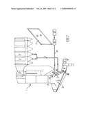
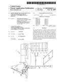
[0015]FIG. 1 shows an embodiment of the boiler using a reactor in combination with a burner applied to generate a non-corrosive gas, and
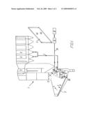
[0016]FIG. 2 shows an embodiment of the boiler using a reactor in combination with a burner applied to generate a non-corrosive gas with a separator element.
[0017]Throughout the drawings, the same reference numerals indicate similar or corresponding features or functions.
[0018]In general the terms "superheater" or "end superheater" refers to a device that heats the steam generated by the boiler further, thereby increasing the thermal energy in the steam and decreasing the likelihood that said steam condenses. Steam, which has been superheated, is logically known as superheated steam; conversely non-superheated steam is called saturated steam or wet steam. It is important to avoid the latter steam and thus primarily to use the superheated steam. Thus, when this latter steam is fed into a steam turbine driving a generator, it will provide a high and efficient electrical power output, especially if the temperature and the pressure of the steam are sufficiently high.
[0019]In general bottom ash is called slag. Bottom ash or slag is defined as the ash removed from the bottom part of the combustion zone of the boiler. Ashes are defined as the residual products from the combustion process.
[0020]FIG. 1 shows an embodiment of the boiler using a reactor in combination with a burner applied to generate a less-corrosive gas. In general, the boiler (1) dries, ignites and combusts refuse. When refuse is incinerated, a gaseous atmosphere, i.e. flue gases (3), is in the first place the result of incineration of refuse (9).
[0021]The reactor (16) can be a sintering reactor, a rotary kiln, a fluidised bed or a spouted bed. The reactor sinters the bottom ash such that the leaching of heavy metals is reduced and the possibilities of utilising the bottom ash are improved.
[0022]The sintering reactor is a reactor that heats the ash/slag so that leaching properties are improved. This means that the leaching of heavy metals from the ash/slag is reduced.
[0023]In fluid beds and fast fluidised beds, smooth and steady recirculation of solids through a dipleg or other solid trapping device is crucial to good operations. In the spouted bed it represents a somewhat related contacting mode in which comparatively coarse, uniformly sized solids are contacted by gas. In this operation, a high velocity spout of gas punches through the bed of solids, thereby transporting particles to the top of the bed. The rest of the solids move downward slowly around the spout and through gently upward percolating gas. Behaviour somewhere between bubbling and spouting is also seen, and this may be called spouted fluidised bed behaviour.
[0024]Said reactor (16) in general burns the refuse and turns it into slag and/or ash. The refuse to be burnt can be any mixtures of household refuse, bark, industrial waste and hospital refuse and other kinds of waste. Typically the refuse is supplied to the reactor--from the left to the right in the figure--by means of grate blocks, e.g. reciprocable grates (21). In order to convey the refuse, the grates can be combined with one or more conveyors.
[0025]The reactor is located--in the direction of the flow of the refuse--after the grate arrangement (21).
[0026]The process of refuse-incineration is now to be followed--from left to right in the figure--starting at reference numeral 3 with flue gases, proceeding to reference numeral 7, and ending at reference numeral 6. At reference numeral 7, a corrosive gas flow is the result in the pre-process, and conversely at reference numeral 6, a less-corrosive gas flow is the result in the post-process. The less-corrosive gas flow is the output from said reactor (16), possibly fired with a fuel (18), typically a secondary fuel (18). The secondary fuel is selected to develop flue gases that are less corrosive than the flue gases from said refuse or waste.
[0027]In this embodiment the reactor is fired from the left-hand side with a secondary fuel (18). The firing follows the direction of the transport of refuse in the reactor, and as a result the less-corrosive gas flow as the output from said reactor is co-current, as indicated with the arrow 6.
[0028]Alternatively, or additionally, the firing of the reactor can take place by means of a burner (19), which can be fired with said secondary fuel (18), i.e. the burner can be fired with any combination of oil, gas, coal, biomass, air and a selected waste or refuse fraction. This also applies when said secondary fuel in addition, or as an alternative, is supplied directly to the reactor instead. Said firing may take place by means of a burner (19) and/or take place in the reactor.
[0029]The burner can be a suspension burner, possibly supplied with coal or a gas, or an oil burner, etc.
[0030]The fuel and air injection into the reactor inlet comes via a separate housing/chute, which is separated from the corrosive flue gas (7).
[0031]Since the reactor is fired, it reaches a higher temperature as compared to a reactor with no firing. This heat is needed to burn out the volatiles and to sinter the waste slag, trace and heavy metal species. This can be considered as a post-treatment process, i.e. the boiler or waste incinerator is combined with the reactor. As a result, the final ash and/or slag from the reactor is--due to its low content of leachable trace and heavy metal species, such as one or more of leachable Pb, As, Cd, Cu, Zn, Ni and Zn well-suited for reuse in road construction, etc and/or for disposal. Accordingly, environmental harm from ash and slag are minimised.
[0032]The ash and/or slag is provided from the reactor by means of a bottom ash or slag removal device, which e.g. is a water filled through a piston pusher or belt conveyor.
[0033]Thus an integrated bottom ash treatment and improved electrical plant efficiency may be obtained by the concepts shown in the figure. It is thus advantageous to combine the high-efficient grate firing of e.g. refuse, such as municipal solid waste, with a post-treatment of the bottom ash (by means of the reactor) in a single plant, so that the final bottom-ash and/or slag produced will fulfil the current environmental and technical restrictions necessary for reuse, and at the same time this integrated post-treatment provides a less-corrosive flue gas (6), which can be applied to increase the end superheater (8) steam temperature and thereby the electrical efficiency of the waste-fired boiler of the plant. The total process is integrated, energy-efficient and contained within a single plant without the need for transporting, storing, and subsequent handling/treatment of the bottom ash and/or slag from the grate in another plant.
[0034]The electrical efficiency of the waste incineration plant is improved significantly due to the generation of the less-corrosive flue gas (6), which will allow higher steam temperatures (around 500 degrees Celsius) at the outlet 8b of the end superheater (8). Furthermore, it makes it possible to dispose of massive amounts of bottom ash and slag from waste incineration due to fixation of otherwise leachable trace and heavy metal fractions.
[0035]Said less-corrosive gas is essentially free from corrosive components, such as Cl, K, Na, Zn, Pb, whereas the corrosive gas comprises corrosive components, e.g. comprises one or more of Cl, K, Na, Zn and Pb. In essence, less-corrosive gas can be understood as gases that provide less corrosion on the end superheater.
[0036]FIG. 2 shows an embodiment of the boiler using a reactor in combination with a burner (19) applied to generate a less-corrosive gas with a separator element.
[0037]In this embodiment the reactor is fired from the right-hand side with a secondary fuel (18). The firing does not follow the direction of the transport of refuse in the reactor, and as a result the less-corrosive gas flow as the output from said reactor is counter current, as indicated with the arrow 6. Note that the reactor is located at the end of the transportation direction of the refuse, which is discharged directly from the grate into the reactor.
[0038]Alternatively, or additionally, the firing of the reactor can take place by means of a burner (19), which can be fired with said secondary fuel (18), i.e. the burner can be fired with any combination of oil, gas, coal, biomass, air and a selected waste or refuse fraction. This also applies when said secondary fuel in addition, or as an alternative, is supplied directly to the reactor instead.
[0039]Since the reactor is fired, it reaches a higher temperature as compared to a reactor with no firing. This heat is needed to burn out the volatiles and to sinter the waste slag, trace and heavy metal species. This can be considered as a post-treatment process, i.e. the boiler or waste incinerator is combined with the reactor. As a result, the final ash and/or slag from the reactor is--due to its low content of leachable trace and heavy metal species, such as one or more of Pb, As, Cd, Cu, Zn, Ni and Zn--well-suited for reuse in road construction, etc and/or for disposal. Accordingly, environmental harm from ash and slag is minimised.
[0040]At this point of the process, it is important that corrosive and less-corrosive gases are not mixed, since these, i.e. reference numerals 6 and 7, are to be treated differently.
[0041]This is because the less-corrosive gas (6) shall be kept separated from the corrosive gas (7) rising from the grate combustion.
[0042]Consequently, according to the invention, a separation is provided to maintain separation of the gases, i.e. in order to protect the end superheater (8) from the corrosive gases (7), whereby it is mainly subjected to the non-corrosive gases (6). Said separation of the flue gases (3) is maintained by means of a separator element denoted with reference numeral 4. This element could in an exemplary embodiment be provided as a plate (4a) or in the form of a wall (4b).
[0043]The plate (4a) is typically a water filled boiler tube panel extending from one boiler side wall, typically also a water filled boiler tube panel, to the other boiler side wall, and the plate is suspended on said side walls. The plate may be corrosion-protected on the surfaces by e.g. high-alloy Cr--Ni overlay welding or by essentially tight refractory materials.
[0044]The wall (4b) is typically a reinforced brick or cast refractory wall extending from the one boiler sidewall to the other boiler sidewall. The reinforcement may be hollow, allowing for passage of a cooling medium being e.g. a liquid, a vapour, a gas or air.
[0045]Moreover, the separator element could in another exemplary embodiment be provided as a channel, i.e. said plate (4a) and wall (4b) could in various combinations be used to form the channel. The channel could also have a tubular shape.
[0046]Thus the separator element secures that the less-corrosive gas flow (6) and the corrosive gas flow (7) are kept separated at this point, and that mainly the less-corrosive gas flow (6) from the reactor (16) reaches the end superheater (8). In the long run, the optimal position of the separator element may be reflected in a high efficiency and high electrical power output from a generator driven by a steam turbine supplied with steam from the boiler.
[0047]The separator element is adapted to be suspendable on or from the walls of the boiler. In an exemplary embodiment, the separator element may be a plate, a wall or channel able to pivot at the top in bearings suspended on the opposite boiler side walls and e.g. being able to move and fixate in different positions forwards/backwards at the bottom onto the boiler side walls.
[0048]In general for any embodiment, i.e. it applies both when the firing takes place from the left-hand side (FIG. 1) and from the right hand side (FIG. 2), said less-corrosive gas (6) and the corrosive gas (7) continue in the boiler to the mixing zone (10) of the boiler (1).
[0049]Also being general for any embodiment is that the steam (2) at between 300 and 450 degrees Celsius, after leaving said one or more superheaters, is fed, by means of one or more pipes, to an inlet (8a) of an end superheater (8), through which this steam (2) is heated, resulting in a temperature increase of between 25 and 200 degrees Celsius.
[0050]This warmer steam (2a), i.e. the steam with the increased temperature, is e.g. supplied from an outlet (8b) of the end superheater (8) to a steam turbine (14). Thus this steam (2a) can be utilised to produce electricity. For example said steam can be fed by means of piping from said outlet into the steam turbine (14), which drives a generator (15), from which generator electrical power then can be generated. Since warmer steam (2a) is the output from the boiler, i.e. the output from the end superheater, the boiler accordingly also provides high power output efficiency. This is, of course, higher than if steam (2) at between 300 and 450 Celsius was the output from the boiler. Thus the heating of the steam in said end superheater provides the high electrical power and high efficiency output.
[0051]Typically said end superheater (8) is located in proximity to said separator element (4), e.g. said plate, wall or into the channel, and in all cases in the flow (6) of said less-corrosive gas. It is thus an advantage that the end superheater is less subject to corrosion.
[0052]It is therefore an advantage--which applies to both figures--that the end superheater is located in the flow of said less-corrosive gas (6) as compared to the flow (7) of said corrosive gas. If the end superheater was located in the flow (7) of said corrosive gas--which is not the case according to the invention--such location of the end superheater would result in a short life time of the end superheater, and this location in the aggressive environment would require excessive and frequent repair work due to being subjected to corrosive gases during its working life time.
[0053]The invention therefore has the advantages that the lifetime of the end superheater is increased and that the boiler provides a high electrical power efficiency.
[0054]As discussed above, said less-corrosive gas (6) and the corrosive gas (7) are mixed together in the mixing zone (10) of the boiler (1). The boiler further comprises a blow unit (12). This is adapted to--by blowing secondary air--effectively mix said less-corrosive gas (6) with said corrosive gas (7), whereby said mix can be effectively burnt out before it reaches the top zone (13) of the boiler. Moreover--this applying to both figures--the boiler is provided with an Industrial Draught fan, which sucks the gases, i.e. flue gases, the less-corrosive and the corrosive gases through the boiler. Additionally, combustion air can be blown in under the grate arrangement (21).
[0055]When said less-corrosive gas (6) and the corrosive gas (7) together reach the mixing zone (10) of the boiler, these gases are mixed by injection of secondary combustion air for outburning, and the now mixed gases are cooled by means of the evaporation wall in the radiation zone and one or more superheaters (11), which produce(s) steam (2) at between 300 and 450 Celsius. This (i.e. cooling by means of said one or more superheaters) takes place regardless of whether the less-corrosive gas (6) has been in contact with the plate, the wall or the channel when it moved in the direction (6) and/or whether it was the result of the firing with the burner to the reactor from the left-hand side or from the right-hand side.
User Contributions:
comments("1"); ?> comment_form("1"); ?>Inventors list |
Agents list |
Assignees list |
List by place |
Classification tree browser |
Top 100 Inventors |
Top 100 Agents |
Top 100 Assignees |
Usenet FAQ Index |
Documents |
Other FAQs |
User Contributions:
Comment about this patent or add new information about this topic:
Images included with this patent application:
 |  |
 |
| Similar patent applications: | |
| Date | Title |
|---|---|
| 2009-10-01 | Water heater with high efficiency baffles |
| 2012-01-26 | Combustion apparatus with improved thermal efficiency |
| 2010-10-28 | Water heater with enhanced thermal efficiency |
| 2012-05-03 | Method and apparatus for draining condensate from a gas water heater exhaust system |
| 2010-12-02 | Water heater apparatus with differential control |
| New patent applications in this class: | |
| Date | Title |
|---|---|
| 2012-06-14 | Lignin fired supercritical or near critical water generator, system and method |
| 2009-04-02 | Municipal solid waste fuel steam generator with waterwall furnace platens |
| Top Inventors for class "Liquid heaters and vaporizers" | |
| Rank | Inventor's name |
|---|---|
| 1 | Jan Brückner |
| 2 | Joachim Franke |
| 3 | Hsin-Ming Huang |
| 4 | Hsing-Hsiung Huang |
| 5 | Emadeddin Y. Tanbour |