Patent application title: FINGER ATTACHED CIGARETTE HOLDER ENABLING ASH TIPPING
Inventors:
Yaron Ben Shitrit (Tel-Aviv, IL)
IPC8 Class: AA24F1308FI
USPC Class:
131190
Class name: Device used for smoking cigar and cigarette holders with movable gripper or holder
Publication date: 2009-02-12
Patent application number: 20090038627
Inventors list |
Agents list |
Assignees list |
List by place |
Classification tree browser |
Top 100 Inventors |
Top 100 Agents |
Top 100 Assignees |
Usenet FAQ Index |
Documents |
Other FAQs |
Patent application title: FINGER ATTACHED CIGARETTE HOLDER ENABLING ASH TIPPING
Inventors:
Yaron BEN SHITRIT
Agents:
Fleit Gibbons Gutman Bongini & Bianco PL
Assignees:
Origin: MIAMI, FL US
IPC8 Class: AA24F1308FI
USPC Class:
131190
Abstract:
A finger attached cigarette holder having a shaft that safely secures the
cigarette to the smoker's finger and positions the cigarette in a safe
distance thus freeing the hands of the smoker and yet enables the smoker
to easily tip the ash off the. The cigarette holder comprises a finger
loop sized to fit a finger, wherein on end of the loop extends outwards
to form an lever and the other end of the loop extend to form a shaft
wherein the shaft ends with a tubular shaped attachment means sized to
hold a cigarette therein. Upon tipping the lever, the cigarette holder
transfers the tipping motion to the cigarette wherein the smoker's finger
provided an elastic counter balance.Claims:
1. A finger attached cigarette holder that safely secures the cigarette to
the smoker's finger thus freeing the hands of the smoker for other
activities, said cigarette holder comprising:a finger loop sized to fit a
finger;a shaft extending from one end of said loop; and connected toa
tubular shaped attachment means sized to hold a cigarette therein;wherein
the shaft positions the cigarette in a distance from the smoker's hands.
2. The cigarette holder of claim 1, further comprising a lever extending outwards from the other end of said loop, wherein upon tipping the lever, the cigarette holder transfers the tipping motion to the cigarette wherein the smoker's finger provides an elastic counter balance and wherein the tipping of the lever results in tipping the ash off the cigarette.
3. The cigarette holder of claim 1, wherein the cigarette holder is made of a bendable material to allow adjustments for different sizes of fingers.
4. The cigarette holder of claim 1, wherein cigarette holder is made of a bendable material to allow adjustments for cigarettes.
5. The cigarette holder of claim 1, wherein the loop is a ring.
6. The cigarette holder of claim 1, wherein the loop is a partial circle.
7. The cigarette holder of claim 1, wherein the tubular shaped attachment means is an unfinished ring.
8. The cigarette holder of claim 1, wherein the loop comprises at least one helix.
9. The cigarette holder of claim 1, wherein cigarette holder is made of one piece of material.
10. The cigarette holder of claim 1, wherein the cigarette holder is made from at least one of the following materials: metal alloy, plastic, hardened polycarbonate, polymer, ceramics.
11. The cigarette holder of claim 1, wherein the lever ends with a bolt.
12. The cigarette holder of claim 1, wherein the shaft is a flat strip enabling writing thereon.
Description:
FIELD OF THE INVENTION
[0001]The present invention relates generally to smoking appliances and more specifically to finger attached cigarette holder.
BACKGROUND OF THE INVENTION
[0002]Smoking a cigarette requires the smoker to use one hand exclusively as well as to be attentive due to the handling of the burning article. However, many cigarette smokers smoke while engaged in other activities and typically lay the cigarette down momentarily in an ashtray or on any available surface of support while using their hands. Smoking and driving can be particularly dangerous since two free hands are required for safe driving. Nevertheless most smokers keep driving while smoking a cigarette albeit the risk.
[0003]Many types of cigarette holders have been developed throughout the years and are well known in the art. One type of cigarette holders is in the form of an extendable mouthpiece connected to the cigarette's filter. Another type of cigarette holders enables the holding of a cigarette from the side in order to provide the smoker with an easy manner of holding. Yet another type of cigarette holders are finger attached cigarette holders. These holders comprise a ring or a similar object that goes around one of the fingers of the smoker wherein the cigarette is attached to a tubular shaped connector that is connected directly to the ring.
[0004]While solving the issue of securely holding the cigarette, the currently available finger attached cigarette holders do not enable the cigarette smokers to use their hands freely. The presently available cigarette holders do not assist in keeping the cigarette in a safe distance from the fingers of the smoker. On another matter, the currently available cigarette holders do not allow the smoker to easily tip the ash off the cigarette in the manner that cigarette smokers are usually accustomed to. It would be therefore advantageous to have a finger attached cigarette holder that enables the tipping of the ash off the cigarette in an easy and simple manner.
SUMMARY OF THE INVENTION
[0005]The present invention discloses finger attached cigarette holder having a shaft that safely secures the cigarette to the smoker's finger and positions the cigarette in a safe distance thus freeing the hands of the smoker and yet enables the smoker to easily tip the ash off the cigarette. The cigarette holder comprises a finger loop sized to fit a finger, wherein on end of the loop extends outwards to form an lever and the other end of the loop extend to form a shaft wherein the shaft ends with a tubular shaped attachment means sized to hold a cigarette therein. Upon tipping the lever, the cigarette holder transfers the tipping motion to the cigarette wherein the smoker's finger provides an elastic counter balance.
[0006]In embodiments the cigarette holder is made of a bendable material to allow adjustments for different sizes of fingers and cigarettes.
[0007]In embodiments, the cigarette holder may be made of variety materials such as any metal alloy, plastic, hardened polycarbonate, polymer, ceramics and the like.
[0008]In embodiments, the lever of the cigarette holder ends with a bolt for easing the tipping movement.
[0009]In embodiments the shaft of the cigarette holder is a flat strip enabling writing thereon. This can be used for advertisement, personal engravings and the like.
BRIEF DESCRIPTION OF DRAWINGS
[0010]The subject matter regarded as the invention will become more clearly understood in light of the ensuing description of embodiments herein, given by way of example and for purposes of illustrative discussion of the present invention only, with reference to the accompanying drawings (Figures, or simply "FIGS."), wherein:
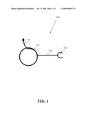
[0011]FIG. 1. is a side view of the finger attached cigarette holder in accordance with the present invention; and
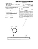
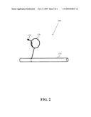
[0012]FIG. 2 is side view of the finger attached cigarette holder with a cigarette fit into it in accordance with the present invention.
[0013]The drawings together with the description make apparent to those skilled in the art how the invention may be embodied in practice.
[0014]Further, where considered appropriate, reference numerals may he repeated among the figures to indicate corresponding or analogous elements.
DETAILED DESCRIPTION OF THE INVENTION
[0015]FIG. 1 is a side view of the finger attached cigarette holder in accordance with the present invention. The cigarette holder 100 comprises a finger loop 120 sized to fit a finger, wherein on end of the loop extends outwards to form an lever 110 and the other end of the loop extend to form a shaft 130 wherein the shaft ends with a tubular shaped attachment means 140 sized to hold a cigarette therein.
[0016]According to the preferred embodiment of the invention, the cigarette holder comprises a shaft that positions the cigarette in a safe distance from the finger thus freeing the hands of the smoker as well as help decreasing the amount of poisonous materials that may affect the smoker when the cigarette is held directly by the smoker's hands.
[0017]According to some embodiments of the invention, the cigarette holder is made of a bendable material to allow adjustments for different sizes of fingers as well as different sizes of cigarettes and may fit cigars as well.
[0018]According to some embodiments of the invention. the loop is in the form of a ring, a partial circle a helix or several loops. The tubular shaped attachment means may be in the form of an unfinished ring, a partial circle, a ring and the like.
[0019]According to some embodiments of the invention, the cigarette holder is made of one piece of material. These materials can be any heat resistive material such as any: metal alloy, plastic, hardened polycarbonate, polymer, ceramics and the like. The cigarette holder may also be comprises of any combination of materials.
[0020]FIG. 2 is a side view of the finger attached cigarette holder 100 with a cigarette fit into it 200 in accordance with the present invention. Upon tipping the lever 110, the finger loop 120 of the cigarette holder 100 transfers the tipping motion to the cigarette 210 wherein the smoker's finger provides an elastic counter balance. This is done due to the fact that the finger loop 120 is configured to fit securely on the finger while allowing slipping along the finger's skin.
[0021]According to some embodiments of the invention, the lever ends with a bolt. This enables the smoker to more easily tip the lever to achieve the tipping of the ash off the cigarette.
[0022]According to some embodiments of the invention, the shaft may he in the form of a flat strip enabling writing thereon. This may be used for advertisement purposes as well as personalized engraving.
[0023]According to some embodiments of the invention, the cigarette holder may comprise precious metals and stones and may serve a piece of jewelry.
[0024]In the above description, an embodiment is an example or implementation of the inventions. The various appearances of "one embodiment," "an embodiment" or "some embodiments" do not necessarily all refer to the same embodiments.
[0025]Although various features of the invention may be described in the context of a single embodiment, the features may also be provided separately or in any suitable combination. Conversely, although the invention may be described herein in the context of separate embodiments for clarity, the invention may also be implemented in a single embodiment.
[0026]Reference in the specification to "some embodiments", "an embodiment", "one embodiment" or "other embodiments" means that a particular feature, structure, or characteristic described in connection with the embodiments is included in at least some embodiments, but not necessarily all embodiments, of the inventions.
[0027]It is understood that the phraseology and terminology employed herein is not to be construed as limiting and are for descriptive purpose only.
[0028]The principles and uses of the teachings of the present invention may be better understood with reference to the accompanying description, figures and examples.
[0029]It is to be understood that the details set forth herein do not construe a limitation to an application of the invention.
[0030]Furthermore, it is to be understood that the invention can be carried out or practiced in various ways and that the invention can be implemented in embodiments other than the ones outlined in the description below.
[0031]It is to be understood that the terms "including", "comprising", "consisting" and grammatical variants thereof do not preclude the addition of one or more components. features, steps, or integers or groups thereof and that the terms are to be construed as specifying components, features, steps or integers.
[0032]If the specification or claims refer to "an additional" element, that does not preclude there being more than one of the additional element.
[0033]It is to be understood that where the claims or specification refer to "a" or "an" element, such reference is not be construed that there is only one of that element.
[0034]It is to he understood that where the specification states that a component, feature, structure, or characteristic "may", "might", "can" or "could" be included, that particular component, feature, structure, or characteristic is not required to be included.
[0035]Where applicable, although state diagrams, flow diagrams or both may be used to describe embodiments, the invention is not limited to those diagrams or to the corresponding descriptions. For example, flow need not move through each illustrated box or state, or in exactly the same order as illustrated and described.
[0036]Methods of the present invention may be implemented by performing or completing manually, automatically, or a combination thereof, selected steps or tasks.
[0037]The term "method" may refer to manners, means, techniques and procedures for accomplishing a given task including, but not limited to, those manners, means, techniques and procedures either known to, or readily developed from known manners, means, techniques and procedures by practitioners of the art to which the invention belongs.
[0038]The descriptions, examples, methods and materials presented in the claims and the specification are not to be construed as limiting but rather as illustrative only.
[0039]Meanings of technical and scientific terms used herein are to he commonly understood as by one of ordinary skill in the art to which the invention belongs, unless otherwise defined.
[0040]The present invention can be implemented in the testing or practice with methods and materials equivalent or similar to those described herein.
[0041]Any publications, including patents, patent applications and articles, referenced or mentioned in this specification are herein incorporated in their entirety into the specification, to the same extent as if each individual publication was specifically and individually indicated to be incorporated herein. In addition, citation or identification of any reference in the description of some embodiments of the invention shall not be construed as an admission that such reference is available as prior art to the present invention.
[0042]While the invention has been described with respect to a limited number of embodiments, these should not be construed as limitations on the scope of the invention, but rather as exemplifications of some of the embodiments. Those skilled in the alit will envision other possible variations, modifications, and applications that are also within the scope of the invention. Accordingly, the scope of the invention should not be limited by what has thus far been described, but by the appended claims and their legal equivalents. Therefore, it is to he understood that alternatives, modifications, and variations of the present invention are to be construed as being within the scope and spirit of the appended claims.
User Contributions:
comments("1"); ?> comment_form("1"); ?>Inventors list |
Agents list |
Assignees list |
List by place |
Classification tree browser |
Top 100 Inventors |
Top 100 Agents |
Top 100 Assignees |
Usenet FAQ Index |
Documents |
Other FAQs |
User Contributions:
Comment about this patent or add new information about this topic:
| People who visited this patent also read: | |
| Patent application number | Title |
|---|---|
| 20150112343 | SYSTEM AND METHOD FOR TREATING BONE FRACTURES |
| 20150112342 | METHODS FOR BONE FIXATION USING AN INTRAMEDULLARY FIXATION IMPLANT |
| 20150112341 | DEVICES FOR BONE FIXATION USING AN INTRAMEDULLARY FIXATION IMPLANT |
| 20150112340 | FIXATION ROBOT FOR BONE FRACTURES |
| 20150112339 | Anatomically personalized and mobilizing external support and method for controlling a path of an external auxiliary frame |
Images included with this patent application:
 |  |
 |
| Similar patent applications: | |
| Date | Title |
|---|---|
| 2009-06-04 | Cigarettes and cigarette components containing nanostructured fibril materials |
| 2010-08-12 | Method for manufacturing and/or packaging cigarettes in a production and/or packaging plant |
| 2010-11-25 | Filtered cigarette possessing tipping material |
| 2011-07-07 | Alexipharmic cigarette filter material and their praparation |
| 2011-06-30 | Electrically heated cigarette including control-release flavoring |
| Top Inventors for class "Tobacco" | |
| Rank | Inventor's name |
|---|---|
| 1 | Qiuming Liu |
| 2 | Munmaya K. Mishra |
| 3 | Qiuming Liu |
| 4 | Stephen Benson Sears |
| 5 | William R. Sweeney |