Patent application title: Hand-Held Power Tool, in Particular a Rotary Hammer and/or Chisel Hammer
Inventors:
Gerhard Meixner (Filderstadt, DE)
IPC8 Class: AB21J720FI
USPC Class:
173216
Class name: Tool driving or impacting means to drive tool about an axis gear drive
Publication date: 2008-12-25
Patent application number: 20080314610
Inventors list |
Agents list |
Assignees list |
List by place |
Classification tree browser |
Top 100 Inventors |
Top 100 Agents |
Top 100 Assignees |
Usenet FAQ Index |
Documents |
Other FAQs |
Patent application title: Hand-Held Power Tool, in Particular a Rotary Hammer and/or Chisel Hammer
Inventors:
Gerhard Meixner
Agents:
MICHAEL J. STRIKER
Assignees:
Origin: HUNTINGTON, NY US
IPC8 Class: AB21J720FI
USPC Class:
173216
Abstract:
The invention is based on a portable power tool, in particular a hammer
drill and/or rotary hammer, comprising a motor unit (10a; 10b; 10c) and a
gear unit (12a; 12b; 12c) and also a machining axis (14a; 14b; 14c). It
is proposed that at least one gear means (16a, 18a, 20a; 16b, 18b, 20b;
18c) of the gear unit (12a; 20 12b; 12c) have a rotation axis (22a, 24a;
22b, 24b; 24c) oriented obliquely to the machining axis (14a; 14b; 14c).Claims:
1. A hand-held power tool, in particular a rotary hammer and/or chisel
hammer, with a motor unit (10a; 10b; 10c) and a transmission unit (12a;
12b; 12c), and with a working axis (14a; 14b; 14c),whereinat least one
transmission element (16a, 18a, 20a; 16b, 18b, 20b; 18c) of the
transmission unit (12a; 12b; 12c) has a rotation axis (22a, 24a; 22b,
24b; 24c) that is oriented diagonally to the working axis (14a; 14b;
14c).
2. The hand-held power tool as recited in claim 1,whereinthe rotation axis (22a, 24a; 22b, 24b; 24c) of the transmission element (16a, 18a, 20a; 16b, 18b, 20b; 18c) has at least one component that extends in the direction of the working axis (14a; 14b; 14c).
3. The hand-held power tool as recited in claim 1,whereinthe transmission element (18a, 20a; 18b, 20b; 18c) is provided at least partially in the form of a gearwheel.
4. The hand-held power tool as recited in claim 1,whereinthe transmission element (20b) is provided in the form of a gear stage.
5. The hand-held power tool as recited in claim 1whereinthe transmission element (16a; 16b) is provided in the form of a shaft.
6. The hand-held power tool as recited in claim 5, wherein the transmission element (16a; 16b) is provided in the form of a motor shaft.
7. The hand-held power tool as recited in claim 1, characterized by an impact mechanism (26a; 26b; 26c).
8. The hand-held power tool as recited in claim 7,whereinthe impact mechanism (26a; 26b; 26c) includes a wobble bearing (28a; 28b; 28c).
9. The hand-held power tool as recited in claim 1, characterized by a motor shaft with an output region (30a; 30b), which is located at least partially on a side of the working axis (14a, 14b) facing away from a center of mass (32a; 32b) of the motor unit (10a; 10b).
10. The hand-held power tool as recited in claim 1, characterized by a motor shaft with an output region (30c) that is located at least partially on a side of a center of mass (32c) of the motor unit (10c) facing away from the working axis (14c).
Description:
RELATED ART
[0001]The present invention is directed to a hand-held power tool according to the definition of the species in Claim 1.
[0002]Hand-held power tools designed as rotary hammers and/or chisel hammers with a motor unit and a transmission unit, and with a working axis serving as a drilling axis and/or impact axis are known. The transmission unit has rotation axes that are oriented either perpendicular or parallel to the working axis.
ADVANTAGES OF THE INVENTION
[0003]The present invention is directed to a hand-held power tool, in particular a rotary hammer and/or chisel hammer, with a motor unit and a transmission unit, and with a working axis.
[0004]It is provided that at least one transmission element of the transmission unit includes a rotation axis that is oriented diagonally to the working axis. A "transmission unit" refers, in particular, to a unit for transferring and/or converting rotary motions. A "working axis" refers, in particular, to a rotation axis of a tool fitting or a tool that is installable in the tool fitting, and/or an impact axis, in the direction of which an impulse on the tool--which is installable in the tool fitting--may be introduced. Furthermore, "oriented diagonally" means, in particular, that the rotation axis is oriented neither parallel nor perpendicular to the working axis, and preferably forms an angle between 95° and 175° or between 5° and 85°, and, particularly preferably, between 100° and 150° or between 10° and 60° with the working axis. With a design of this type, a very compact design may be attained and, in particular, the overall length may be reduced, in particular when the rotation axis of the transmission element includes at least one component that extends in the direction of the working axis.
[0005]The transmission element may be provided in the form of various elements that appear reasonable to one skilled in the art, e.g., bearing axes, pulleys, etc., and particularly advantageously, they may be provided at least partially in the form of a gearwheel and/or a shaft, by way of which a compact design and an advantageous power flow may be attained. When the transmission element is provided in the form of a motor shaft--which should also be regarded as the transmission element in the sense of the present invention--the motor unit in particular may be integrated in a hand-held power tool housing in a particularly space-saving manner. Furthermore, the position of a center of mass of the motor unit may be advantageously tailored to basic conditions. A "motor shaft" refers, in particular, to a shaft that is driveable directly using a turbine unit and/or an electromagnetic unit of the motor unit.
[0006]Furthermore, installation space may be spared when the transmission element is provided in the form of a gear stage. A "gear stage" refers, in particular, to a unit that includes different input and output radii. Torque is introduced into the gear stage via by the input radius, and torque is transmitted to a corresponding component via the output radius.
[0007]The inventive means of attaining the object of the present invention is basically suited for use with all hand-held power tools that appear reasonable to one skilled in the art, and particularly advantageously for hand-held power tools with an impact mechanism, so that a particularly compact design may be attained despite the need to provide additional components for the impact mechanism.
[0008]The impact mechanism may include various drive units for converting a rotary motion into an impact motion, such as an eccentric unit or, advantageously, a wobble bearing, which may also be integrated in a particularly space-saving manner. A "wobble bearing" refers, in particular, to a bearing with which, due to a wobble element supported obliquely in a bearing means, a wobbling motion of the wobble element results when the bearing element rotates.
[0009]In a further embodiment of the present invention it is provided that the hand-held power tool includes a motor shaft with an output region that is located at least partially on a side of the working axis facing away from a center of mass of the motor unit, by way of which an overall height, in particular, which is defined by other components, may be used advantageously for the motor unit and the motor shaft, and, in all, a minimal overall height may be attained. The same applies when the hand-held power tool includes a motor shaft with an output region that is located at least partially on a side of the working axis facing away from a center of mass of the motor unit.
DRAWING
[0010]Further advantages result from the description of the drawing, below. Exemplary embodiments of the present invention are shown in the drawing. The drawing, the description and the claims contain numerous features in combination. One skilled in the art will also advantageously consider the features individually and combine them to form further reasonable combinations.
[0011]FIG. 1 shows a schematic depiction of a hand-held power tool, in a side view, with a cut-away view,
[0012]FIG. 2 shows an alternative hand-held power tool with a special gear stage, and
[0013]FIG. 3 shows an alternative hand-held power tool with a specially positioned output region of a motor shaft.
DESCRIPTION OF THE EXEMPLARY EMBODIMENTS
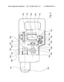
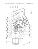
[0014]FIG. 1 shows a hand-held power tool designed as a rotary hammer, with a hand-held power tool housing 34a, a motor unit 10a located in hand-held power tool housing 34a and provided in the form of an electric motor, and a transmission unit 12a, which is provided to transfer a drive force from motor unit 10a to a piston 36a of an impact mechanism 26a of the hand-held power tool. Piston 36a is guided in the direction of a working axis 14a, in the direction of which impact impulses may be generated by impact mechanism 26a. During operation, the impact impulses are transmitted to a tool, which is installable in a tool fitting 40a, is designed as a chisel, and is not shown. Transmission unit 12a includes a transmission element 16a provided in the form of a motor shaft, a transmission element 18a provided in the form of a motor pinion, and a transmission element 20a with the motor pinion, which is provided in the form of a gearwheel, the rotation axes 22a, 24a of which are oriented diagonally to working axis 14a of the hand-held power tool. Rotation axes 22a, 24a of transmission elements 16a, 18a, 20a have components that extend in the direction of working axis 14a, and are tilted in the direction such that their region facing a top 46a of hand-held power tool housing 34a points toward tool fitting 40a. Rotation axis 22a of transmission element 16a provided in the form of the motor shaft, and of transmission element 18a provided in the form of the motor pinion form an angle 42a of approximately 105° with working axis 14a. Instead of installing a motor pinion on the motor shaft, a motor pinion could also be formed as a single piece on the motor shaft.
[0015]Motor unit 10a has a central longitudinal axis that is coaxial with rotation axis 22a, and which is also oriented diagonally to working axis 14a. Rotation axis 24a of transmission element 20a, which is provided in the form of the gearwheel and meshes with the motor pinion, forms an angle 44a of approximately 145° with working axis 14a.
[0016]An output region 30a of the motor shaft, which is provided in the form of the motor pinion and via which the motor pinion meshes with transmission element 20a provided in the form of the gearwheel, is located on a side of working axis 14a facing away from a center of mass 32a of motor unit 10a, and/or output region 30a is located on the side--relative to working axis 14a--facing top 46a of hand-held power tool housing 34a. Transmission element 20a provided in the form of the gearwheel meshes with a further gearwheel 56a provided in the form of a bevel gear, which is non-rotatably mounted on a shaft 48a of impact mechanism 26a, which is oriented parallel to working axis 14a. As an alternative, a motor pinion could also be coupled directly with a gearwheel mounted on shaft 48a.
[0017]A bearing element 50a of a wobble bearing 28a of impact mechanism 26a is non-rotatably mounted on shaft 48a--at a distance from gearwheel 56a, in the direction of tool fitting 40a. A wobble finger 52a is mounted on bearing element 50a of a wobble bearing 28a of impact mechanism 26a such that it is diagonal to the orientation of shaft 48a. Wobble finger 52a is coupled in a driving manner with piston 36a, which is guided in a hammer tube 54a in the direction of working axis 14a.
[0018]During operation, torque produced by motor unit 10a is transmitted to transmission element 16a provided in the form of the motor shaft, from transmission element 16a via transmission element 18a provided in the form of the motor pinion, via transmission element 20a provided in the form of the gearwheel, via gearwheel 56a and shaft 48a to bearing element 50a of wobble bearing 28a, which--in combination with wobble finger 52a--generates a motion of piston 36a that moves back and forth in the axial direction, i.e, in the direction of working axis 14a. To cool motor unit 10a, a fan wheel 58a is mounted on the motor shaft on the side of motor unit 10a facing away from the motor pinion.
[0019]Alternative hand-held power tools are shown in FIGS. 2 and 3. Components, features, and functions that are essentially the same are labelled with the same reference numerals. To distinguish the exemplary embodiments from each other, the reference numerals of the exemplary embodiments are appended with the letters a, b, and c. The description below is essentially limited to the differences from the exemplary embodiment in FIG. 1. With regard for the components, features, and functions that remain the same, reference is made to the description of the exemplary embodiment in FIG. 1.
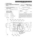
[0020]The hand-held power tool provided in the form of a chisel hammer and shown in FIG. 2 includes a transmission unit 12b, which includes a transmission element 16b provided in the form of a motor shaft, a transmission element 18b provided in the form of a motor pinion, and a transmission element 20b with the motor pinion provided in the form of a gear stage, the rotation axes 22b, 24b of which are oriented diagonally to a working axis 14b of the hand-held power tool. Gear element 20b includes two gearwheels 60b, 62b. Gearwheel 60b meshes via its spur toothing with transmission element 18b provided in the form of the motor pinion, and gearwheel 62b--which has a smaller diameter and is provided in the form of a bevel pinion--meshes with a gearwheel 56b, which is mounted on a shaft 48b of an impact mechanism 26b and is provided in the form of a crown wheel.
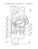
[0021]The hand-held power tool provided in the form of a chisel hammer and shown in FIG. 3 includes a transmission unit 12c, which includes a transmission element 16c provided in the form of a motor shaft, and a transmission element 18c provided in the form of a motor pinion, the rotation axis 22c of which forms an angle 42c of approximately 90° with a working axis 14c. Furthermore, transmission unit 12c includes a transmission element 20c with the motor pinion, provided in the form of a bevel gear, rotation axis 24c of which is oriented diagonally to working axis 14c of the hand-held power tool. Rotation axis 24c of transmission element 20c includes a component that extends in the direction of working axis 14c. Rotation axis 24c is tilted in the direction such that its region facing a top 46c of a hand-held power tool housing 34c points away from a tool fitting 40c. Rotation axis 24c of transmission element 20c forms an angle 44c of approximately 50° with working axis 14c. Transmission element 20c meshes--on a side facing away from the motor pinion--with a bevel gear 56c, which is non-rotatably mounted on a shaft 48c of an impact mechanism 26c.
[0022]An output region 30c of the motor shaft, which is provided in the form of the motor pinion and via which the motor pinion meshes with transmission element 20c provided in the form of the gearwheel, is located on a side of a center of mass 32c of motor unit 10c facing away from working axis 14c. Transmission unit 20c provided in the form of the motor pinion is located on a side facing an underside 38c--relative to center of mass 32c--of motor unit 10c of hand-held power tool housing 34c.
TABLE-US-00001 Reference numerals 10 Motor unit 12 Transmission unit 14 Working axis 16 Transmission element 18 Transmission element 20 Transmission element 22 Rotation axis 24 Rotation axis 26 Impact mechanism 28 Wobble bearing 30 Output region 32 Center of mass 34 Hand-held power tool housing 36 Piston 38 Underside 40 Tool fitting 42 Angle 44 Angle 46 Top 48 Shaft 50 Bearing element 52 Wobble finger 54 Hammer tube 56 Gearwheel 58 Fan wheel 60 Gearwheel 62 Gearwheel
User Contributions:
comments("1"); ?> comment_form("1"); ?>Inventors list |
Agents list |
Assignees list |
List by place |
Classification tree browser |
Top 100 Inventors |
Top 100 Agents |
Top 100 Assignees |
Usenet FAQ Index |
Documents |
Other FAQs |
User Contributions:
Comment about this patent or add new information about this topic:
| People who visited this patent also read: | |
| Patent application number | Title |
|---|---|
| 20110096326 | SCANNING SPECTROMETER WITH MULTIPLE PHOTODETECTORS |
| 20110096325 | METHOD AND DEVICE FOR THE SPECTROMETRIC MEASUREMENT OF A MATERIAL FLOW MOVING IN THE LONGITUDINAL DIRECTION |
| 20110096324 | RETICLE DEFECT INSPECTION APPARATUS AND RETICLE DEFECT INSPECTION METHOD |
| 20110096323 | OPTICAL-FIBER CONNECTOR WITH ACCURATE MEASURING REFERENCE |
| 20110096322 | OPTICAL POSITION DETECTION DEVICE AND DISPLAY DEVICE WITH POSITION DETECTION FUNCTION |
Images included with this patent application:
 |  |
 |  |
| Similar patent applications: | |
| Date | Title |
|---|---|
| 2012-07-26 | Power tool, particularly a hand power tool, the housing parts thereof being connected by means of form-fitting elements |
| 2012-05-31 | Machine tool, in particular handheld machine tool |
| 2012-06-07 | Machine tool, in particular hand machine tool |
| 2010-02-04 | Handheld power tool with vibration-damped handle |
| 2008-10-09 | Percussive tool, in particular for surgucal use |
| New patent applications in this class: | |
| Date | Title |
|---|---|
| 2016-07-14 | Portable power tool |
| 2016-07-14 | Torque delivering power tool with flywheel |
| 2016-06-30 | Power tool with flywheel and gear for accelerating said flywheel |
| 2016-06-16 | Handheld tool device |
| 2016-05-05 | Handheld machine-tool device |
| New patent applications from these inventors: | |
| Date | Title |
|---|---|
| 2012-07-26 | Holding device for hand machine tools, in particular holding device for a drill and/or chipping hammer |
| 2011-03-31 | Hammer drill and/or chisel hammer |
| 2010-12-30 | Striking mechanism for a handheld electric power tool |
| 2010-11-25 | Hand tool machine |
| 2010-08-19 | Handheld power tool with a handle vibration-damped by compensating means |
| Top Inventors for class "Tool driving or impacting" | |
| Rank | Inventor's name |
|---|---|
| 1 | Heiko Roehm |
| 2 | Tobias Herr |
| 3 | Masanori Furusawa |
| 4 | Daniel Puzio |
| 5 | Hiroki Ikuta |