Patent application title: Bi-directional boat anchor
Inventors:
Rhett Kenneth Bryant (Covington, GA, US)
IPC8 Class: AB63B2144FI
USPC Class:
114304
Class name: Anchor fluke type pivoted fluke
Publication date: 2008-12-25
Patent application number: 20080314305
Inventors list |
Agents list |
Assignees list |
List by place |
Classification tree browser |
Top 100 Inventors |
Top 100 Agents |
Top 100 Assignees |
Usenet FAQ Index |
Documents |
Other FAQs |
Patent application title: Bi-directional boat anchor
Inventors:
Rhett Kenneth Bryant
Agents:
MICHAEL J. BOOTCHECK, LLC
Assignees:
Origin: MCDONOUGH, GA US
IPC8 Class: AB63B2144FI
USPC Class:
114304
Abstract:
This invention relates to marine anchors and more particularly to
bi-directional boat anchors with a shank which is pivotable relative to
at least one fluke. The invention also relates to bi-directional anchors
that have two or more flukes positioned at opposite ends of the anchor.Claims:
1. A bi-directional boat anchor comprising:an anchor lower portion having
a first fluke at one end and a second fluke at a distal end and a
longitudinal axis therebetween;a shank having a shank first end and a
shank second end with a longitudinal axis therebetween;a channel located
within said shank and having a shank first end and a shank second end;
andwherein said shank is pivotally connected to said fluke to allow said
shank to pivot about a pivot axis.
2. The anchor of claim 1 wherein said channel extends over a majority of a length of said shank portion.
3. The anchor of claim 1 wherein said channel extends from a channel first end which is proximate said shank first end to a channel second end which is proximate said shank second end.
4. The anchor of claim 1 wherein said pivot axis is positioned at least thirty percent of a distance between said shank first end and said shank second end.
5. The anchor of claim 1 wherein said channel is slidably engageable by an anchor line and allowing said anchor line to slide between said channel first end and said channel second end.
6. The anchor of claim 1 wherein said pivot axis is positioned at an approximate midpoint between said shank first end and said shank second end.
7. The anchor of claim 1 wherein said at least one fluke includes a first fluke and a second fluke.
8. The anchor of claim 1 wherein said anchor is manufactured by a method selected from the following group: die casting, molded, extrusion, machining, or any combination thereof.
9. The anchor of claim 1 wherein at least a portion of said anchor is comprised of a material selected from the group consisting of aluminum, wood, concrete, steel, stainless steel, ceramic, and lead.
10. A boat anchor comprising:a fluke plate;a first fluke and a second fluke positioned at opposite ends of said fluke plate;a shank have a shank first end proximate said first fluke and a shank second end proximate said second fluke;a channel positioned within said shank;wherein said shank is pivotably connected to said fluke plate at a pivot point wherein said pivot point is approximately equidistant from said shank first end and said shank second end.
11. The anchor of claim 10 wherein said channel extends over a majority of a length of said shank portion.
12. The anchor of claim 10 wherein said channel extends from a channel first end which is proximate said shank first end to a channel second end which is proximate said shank second end.
13. The anchor of claim 10 wherein said pivot axis is positioned at least thirty percent of a distance between said shank first end and said shank second end.
14. The anchor of claim 10 wherein said channel is slidably engageable by an anchor line and allowing said anchor line to slide between said channel first end and said channel second end.
15. The anchor of claim 10 wherein said pivot axis is positioned at an approximate midpoint between said shank first end and said shank second end.
16. The anchor of claim 10 wherein said at least one fluke includes a first fluke and a second fluke.
17. The anchor of claim 10 wherein said anchor is manufactured by a method selected from the following group: die casting, molded, extrusion, machining, or any combination thereof.
18. The anchor of claim 10 wherein at least a portion of said anchor is comprised of a material selected from the group consisting of aluminum, wood, concrete, steel, stainless steel, ceramic, and lead.
Description:
FIELD OF THE INVENTION
[0001]This invention relates to marine anchors and more particularly to bi-directional boat anchors with a shank which is pivotable relative to at least one fluke. The invention also relates to bi-directional anchors that have two or more flukes positioned at opposite ends of the anchor.
BACKGROUND OF THE INVENTION
[0002]Boat anchors are conventionally carried at the end of an anchor line, chain or cable and comprise one or more flukes which are employed to embed in the sea floor to temporarily anchor the vessel.
[0003]It is well-known in the art that various problems plague such anchors, for example, (i) they become entangled on the sea floor or are otherwise difficult to retrieve when they are embedded on the sea floor, and (ii) they are inefficient or provide insufficient holding power.
[0004]Though there has been a constant effort to improve the efficiency, design and manufacture of such boat anchors, there has not been an anchor that satisfactorily addressed these two issues.
SUMMARY OF THE INVENTION
[0005]The present invention addresses some of the difficulties and problems discussed above by the discovery of anchors which include a pivotable shank such that the anchor may be reversible or bi-directional and may be more easily disengaged from the sea floor and other obstructions.
[0006]Accordingly, in one exemplary embodiment, the present invention is directed to a bidirectional boat anchor comprising: an anchor lower portion having a first fluke at one end and a second fluke at a distal end and a longitudinal axis therebetween, a shank having a shank first end and a shank second end with a longitudinal axis therebetween, a channel located within the shank and having a shank first end and a shank second end, and wherein the shank is pivotally connected to the fluke to allow the shank to pivot about a pivot axis.
[0007]In another exemplary embodiment, the present invention is directed to a boat anchor comprising: a fluke plate, a first fluke and a second fluke positioned at opposite ends of the fluke plate, a shank having a shank first end proximate the first fluke and a shank second end proximate the second fluke, a channel positioned within the shank; wherein the shank is pivotably connected to the fluke plate at a pivot point wherein the pivot point is approximately equidistant from the shank first end and the shank second end.
[0008]These and other features and advantages of the present invention will become apparent after a review of the following detailed description of the disclosed embodiments and the appended claims.
BRIEF DESCRIPTION OF THE FIGURES
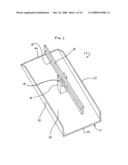
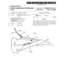
[0009]FIG. 1 depicts a perspective view of an exemplary boat anchor of the present invention;
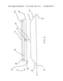
[0010]FIGS. 2 depicts a side view of the exemplary anchor of FIG. 1;
[0011]FIG. 3 depicts an end view of the exemplary anchor of FIG. 1;
[0012]FIG. 4 depicts an exploded view of exemplary components which may comprise the exemplary anchor of FIG. 1;
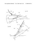
[0013]FIG. 5A depicts a view of the exemplary boat anchor of FIG. 1 when the anchor is set into the sea floor;
[0014]FIG. 5B depicts a view of the exemplary boat anchor of FIG. 1 when the anchor is being retrieved from the sea floor;
[0015]FIGS. 6A-6E depict exemplary fluke and multiple fluke geometries;
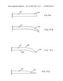
[0016]FIGS. 7A-C depict exemplary cross-sectional shapes for fluke plate 24;
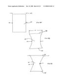
[0017]FIGS. 8A-C depict a top view of exemplary shapes for fluke plate 24; and
[0018]FIGS. 9A-9B depict side view and top views, respectively, of an embodiment of anchor 10.
DETAILED DESCRIPTION OF THE INVENTION
[0019]To promote an understanding of the principles of the present invention, descriptions of specific embodiments of the invention follow and specific language is used to describe the specific embodiments. It will nevertheless be understood that no limitation of the scope of the invention is intended by the use of specific language. Alterations, further modifications, and such further applications of the principles of the present invention discussed are contemplated as would normally occur to one ordinarily skilled in the art to which the invention pertains.
[0020]The present invention is directed to boat anchors that have one or more flukes. One exemplary anchor 10 of the present invention is shown in FIGS. 1-4. FIGS. 5A-B depict an anchor in place on a sea floor. FIGS. 6A-6E depict exemplary fluke and multiple fluke geometries. FIGS. 7A-C depict exemplary cross-sectional shapes for the anchor lower portion 11 or fluke plate 24. FIGS. 8A-C depict top views of exemplary shapes for anchor lower portion 11 or fluke plate 24. FIGS. 9A-9B depict side view and top views, respectively, of an embodiment of anchor 10.
[0021]FIG. 1 illustrates a perspective view of an exemplary anchor 10. In this embodiment, anchor 10 is comprised of anchor lower portion 11, spacer or support 20, shank 14, and pin 16. Anchor lower portion 11 may be comprised of various components and, in the illustrated embodiment, in this embodiment is comprised of first fluke 52 and second fluke 54. In the illustrated embodiment, first fluke 52 and second fluke 54 are each comprised of fluke side panels 22 and fluke plate 24. Though in this embodiment fluke side panels 22 are contiguous from fluke 52 to fluke 54, such need not be the case and each fluke may be comprised of any number of fluke side panels (or even none at all). Further, even if fluke side panels form a part of the fluke or flukes, the fluke side panels need not be contiguous. In the illustrated embodiment, flukes 52, 54 are plow or scoop-shaped such that they may hold sediment or other materials when in use. Other fluke shapes may also be used as further discussed below (some of which will allow for holding more or less sediment than the scoop-shaped flukes illustrated in FIGS. 1-4). Also seen in the illustrated embodiment is that shank 14 has a longitudinal slot or channel 18 therein which may be slidably engageable to receive an anchor line or link (see FIGS. 5A-B).
[0022]FIG. 2 illustrates a side view of the exemplary anchor of FIG. 1. FIG. 2 illustrates an arrangement of shank 14 to other components of anchor 10 including flukes 52, 54, support 20, and pin 16. In this embodiment, pin 16 defines a pivot axis P1 (see FIGS. 3 and 9A) between shank 14 and anchor lower portion 11. In this embodiment, first fluke 52 is at one end and second fluke 54 is at a distal end of anchor lower portion 11 and a longitudinal axis L0 is defined therebetween and that shank 14 has a shank first end 42 and a shank second end 46 with a longitudinal axis L1 therebetween. Also illustrated are channel first end 48 and channel second end 50 which are located proximate shank first end 42 and shank second end 46, respectively. Note that the illustrated embodiment is symmetrical about pivot axis P1, such that anchor 10's center of gravity is in line with pivot axis P1. Also note that although shank 14 is illustrated as having a rectangular shape, it may be of any suitable shape including, but not limited to, arcing, rounded, elliptical, and curved.
[0023]As further described below and with reference to FIGS. 5A-B, an angle Θ is defined by the angle between longitudinal axis L0 and longitudinal axis L1. Note that in the embodiment illustrated in FIG. 2, angle Θ is equal to zero degrees (0°).
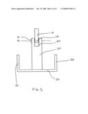
[0024]FIG. 3 illustrates an end view of the exemplary anchor of FIGS. 1-2. The embodiment illustrated shows spacer 20 having a cavity 90 which is sized to be able to receive shank 14 therein. Pin 16, or any other suitable means, may then be inserted through holes in spacer 20 and hole in shank 14 such that shank 14 is able to pivot in cavity 90 about pin 16.
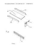
[0025]FIG. 4 illustrates an exploded view of exemplary components of the embodiment illustrated in FIGS. 1-3. The illustrated anchor 10 may include fluke side panels 22, fluke plate 24, spacer 20, pin 16, shank 14.
[0026]Spacer 20 may be rigidly or flexibly attached to fluke plate 24. In another embodiment, spacer 20 may be attached to one or more other components of anchor 10 including, but not limited to, fluke side panel(s) 22. Spacer 20 may be comprised of any suitable materials including, but not limited to, rigid materials such as metals, alloys, ceramics, plastics, etc. or of flexible or bendable materials including, but not limited to, rope, chain, cable, plastics, etc. If support 20 is comprised of a flexible material, note that pin 20 may not be necessary as a flexible support 20 may permit shank 14 to pivot relative to anchor lower portion 11 without need of pins or other pivot means. Further, spacer 20 may also be pivotally connected to fluke plate 24 (or another anchor component) such that spacer 20 may be pivoted to be in a position other than perpendicular to fluke plate 20 as illustrated (see e.g., FIGS. 9A-9B). By pivoting spacer 20 in such a manner, it may allow the anchor to have a lower overall height for storage purposes than a similar anchor which is not so pivotable.
[0027]FIG. 5A illustrates anchor 10 having two flukes 52, 54 at opposite ends of anchor 10. In this embodiment a first fluke 52 is positioned at one end of anchor 10 while second fluke 54 is positioned at a second end of anchor 10. Anchor 10 may be set in the orientation illustrated in FIG. 5A initially by dropping the anchor from a boat or other sea vessel in a conventional manner. After anchor 10 has been placed into the water column, it may sink due its weight or be otherwise urged to impact a sea floor 48. After anchor 10 strikes sea floor, anchor 10 may be further driven to penetrate the sea floor by either driving the sea vessel in the direction of arrow 92 or by allowing currents to drag the sea vessel in the direction of arrow 92 such that anchor line 49 pulls link 51 to one of channel ends 48, 50 of shank 14 (i.e., channel first end 48 in FIG. 5A).
[0028]In FIG. 5A, anchor 10 is engaged with sea floor 48 such that one of flukes 52, 54 is at least partially embedded in sea floor 48. As anchor 10 is driven into (or dragged along) sea floor 55, sediment or sea floor material 53 may accumulate in fluke 52, 54. In such a condition, anchor 10 provides a certain amount of holding power which can be translated from sea floor 48, through anchor 10, through anchor line 49 to a sea vessel above (not shown). In the illustrated embodiment, and as discussed above, shank 14 is able to pivot about pin 16 (or other pivot means including, but not limited to, hinges, ball bearings, and a flexible spacer 20) such that shank 14's orientation can be varied, i.e., angle Θ can be varied. In the illustration shown in 5A, fluke first end 40 and shank first end 42 are separated by a distance D1 and fluke second end 44 and shank second end 46 are separated by a distance D2.
[0029]In transitioning anchor 10 to the configuration shown in FIG. 5B, the relationship or orientation between shank 14 and flukes 52, 54 has changed such that angle Θ has decreased from a positive angle to a negative angle. In FIG. 5A, Θ is approximately forty-five degrees (45°) whereas in FIG. 5B, Θ is approximately negative forty-five degrees (-45°). In another embodiment, Θ may vary from about ninety degrees (90°) to negative ninety degrees (-90°). In another embodiment, Θ may vary from about sixty degrees (60°) to negative sixty degrees (-60°). In another embodiment, Θ may vary from about forty-five degrees (45°) to negative forty-five degrees (-45°). In yet another embodiment, Θ may vary from about thirty degrees (30°) to about negative thirty degrees (-30°).
[0030]Such an orientation change can be accomplished by causing anchor line 49 to move from the position illustrated in FIG. 5A to the position in FIG. 5B. That is to say that the sea vessel may cause anchor line 49 to move link 51 from first channel end 48 to second channel end 50. Once link 51 has moved beyond a center point in channel 18, tension may be increased on anchor line 49 to cause distance D2 between shank second end 46 and fluke second end 44 to increase and anchor 10 can then be raised. In the illustrated embodiment, this point would correspond to the pivot point (i.e., pin 16 and pin pivot axis P1 which is also, in this configuration, in line vertically with anchor 10's center of mass and center of gravity since anchor 10 is symmetrical. Once this change in orientation has occurred, anchor 10 will have substantially less holding power and can easily be removed from sea floor 55.
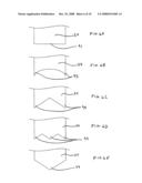
[0031]In the illustrated embodiment, fluke 52, 54 can be of varied shape. FIGS. 6A-6E illustrate exemplary fluke and multiple fluke geometries. FIG. 6A illustrates an embodiment having a singular fluke with a flat front 91. FIG. 6B illustrates an embodiment having two scalloped shaped flukes 93. FIG. 6C illustrates an embodiment having two triangular flukes 95. FIG. 6D illustrates an embodiment having a sawtooth shape with multiple flukes 97. FIG. 6E illustrates an embodiment having a pointed fluke shape 99.
[0032]According to the present invention, fluke plate 24 can be of varied shape. FIGS. 7A-6C illustrate exemplary cross-sectional shapes for fluke plate 24. FIG. 7A illustrates fluke plate 24 having a planar cross-section 60. FIG. 7B illustrates fluke plate 24 having a bend 62 such that front portion 64 of fluke plate 24 is not co-planar with other portions e.g., portion 66, of fluke plate 24. FIG. 7C illustrates fluke plate 24 having a curved portion 68.
[0033]As discussed above, fluke plate 24 can be of any suitable configuration. FIGS. 8A-8C illustrate various top-view geometries of fluke plate 24. FIG. 8A illustrates a rectangularly shaped fluke plate 24. FIG. 8B illustrates fluke plate 24 having flared fluke ends 80, 82. FIG. 8C illustrates fluke plate having a narrower center section with wider ends 86, 88. In these embodiments a first width W1 may be variable with a second width W2. In the illustrated embodiment of FIG. 8A, first width W1 may be equal to second width W2 such that fluke plate 24 is of a fairly uniform width. FIGS. 8B and 8C illustrate embodiments wherein first width W1 is larger than second width W2. Though these embodiments illustrate curved or straight edges for fluke plate 24, fluke plate 24's edges may be of any suitable shape and configuration.
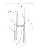
[0034]As discussed above, spacer 20 can be of any suitable material and geometry. FIGS. 9A and 9B illustrate an embodiment of anchor 10 wherein spacer 20 has two pivot pins 16, 17, two spacers 21 and a base support 23. FIG. 9A illustrates a side-view of anchor 10 in which two spacers 21 are (i) pivotably connected with shank 14 via pin 16, and (ii) pivotably connected to fluke plate 24 by way of a pin 17 in combination with base support 23. In this embodiment, pin 17 may be inserted through holes in spacers 21 and through a hole in base support 23 such that spacers 21 are pivotally connected to base support 23. Base support 23 may then be affixed (permanently or temporarily) to fluke plate 24. In this embodiment, a second pivot axis P2 is defined by pin 17 wherein second pivot axis P2 may be parallel with pivot axis P1.
[0035]FIG. 9B illustrates a side view of the embodiment of FIG. 9A. FIG. 9B shows a relationship between shank 14, pins 16, 17, spacers 21, base support 23 and fluke plate 24.
[0036]Methods of Making an Anchor
[0037]The present invention is also directed to a method of making an anchor. Any conventional metal shaping step may be used to form one or more of the various components of an anchor and/or the entire anchor according to the present invention. Suitable methods for making these components of the present invention include, but are not limited to, die casting, molded, extrusion, machining, or any combination thereof.
[0038]Anchor 10 may be molded or shaped out of any suitable material, including, but not limited to, metal, steel, aluminum, plastic, wood, or any combination thereof as would be evident to one skilled in the art. In one exemplary embodiment, anchor 10 comprises steel. In another exemplary embodiment, at least a portion of anchor 10 comprises a material that is rust resistant such as plastic, stainless steel, aluminum or rubber.
[0039]In the embodiment illustrated in FIGS. 1-4, several of the illustrated components, i.e., fluke side panels 22, fluke plate 24 and spacer 20 may be welded, glued, bonded, smelted, riveted, stapled, pinned, soldered, bolted, or otherwise attached to each other such that they are permanently attached or removably attached. In some embodiments, one or more of these components may be hingedly or pivotably attached to another member.
[0040]While the specification has been described in detail with respect to specific embodiments thereof, it will be appreciated that those skilled in the art, upon attaining an understanding of the foregoing, may readily conceive of alterations to, variations of, and equivalents to these embodiments. Accordingly, the scope of the present invention should be assessed as that of the appended claims and any equivalents thereto.
User Contributions:
comments("1"); ?> comment_form("1"); ?>Inventors list |
Agents list |
Assignees list |
List by place |
Classification tree browser |
Top 100 Inventors |
Top 100 Agents |
Top 100 Assignees |
Usenet FAQ Index |
Documents |
Other FAQs |
User Contributions:
Comment about this patent or add new information about this topic:
Images included with this patent application:
 |  |
 |  |
 |  |
 |  |
 |  |
 |
| Similar patent applications: | |
| Date | Title |
|---|---|
| 2014-05-15 | Anti-collision device made of buffering energy-absorbing type web-enhanced composite material |
| 2014-05-15 | Lightweight recreational boat |
| 2014-05-01 | Autonomous sailboat for oceanographic monitoring |
| 2010-11-11 | Sectionalized mast track |
| 2010-03-11 | Sectional boat |
| New patent applications in this class: | |
| Date | Title |
|---|---|
| 2014-09-18 | Offshore marine anchor |
| 2013-06-27 | Gravity installed anchor |
| 2013-02-07 | Offshore marine anchor |
| Top Inventors for class "Ships" | |
| Rank | Inventor's name |
|---|---|
| 1 | Joop Roodenburg |
| 2 | Mehmet Nevres Ulgen |
| 3 | Rolf Rohden |
| 4 | Peter A. Mueller |
| 5 | Frank M. Stewart |