Patent application title: Special equipment and improved methods to install a unitized post tension block system for masonry structures
Inventors:
Roger F. Marsh (Alexandria, IN, US)
Patricia M. Marsh (Alexandria, IN, US)
IPC8 Class: AE04F2100FI
USPC Class:
5274913
Class name: Static structures (e.g., buildings) machine or implement masonry
Publication date: 2008-12-18
Patent application number: 20080307748
Inventors list |
Agents list |
Assignees list |
List by place |
Classification tree browser |
Top 100 Inventors |
Top 100 Agents |
Top 100 Assignees |
Usenet FAQ Index |
Documents |
Other FAQs |
Patent application title: Special equipment and improved methods to install a unitized post tension block system for masonry structures
Inventors:
Roger F. Marsh
Patricia M. Marsh
Agents:
RITCHISON LAW OFFICES, PC
Assignees:
Origin: ANDERSON, IN US
IPC8 Class: AE04F2100FI
USPC Class:
5274913
Abstract:
A special leveling device for use in constructing various types of masonry
structures. The devices permit the leveling of an aggregate base for a
foundation quickly and accurately. The new leveling device sled is
comprised of a flat base float featuring an angular or flat front lead
section; a handle; and a signal receiver unit. The receiver unit is
comprised of an electronic level receiver and an analog level indicator.
The sled device is used in coordination with a laser signal generator
that sends a continuous laser beam out from a given position at a
predetermined, set height.Claims:
1. A new and unique leveling sled comprising:a) flat base float structure
featuring an angular lead section;b) a handle; andc) a signal receiver
unitwhereby the leveling sled receives a signal and permits an operator
to move the sled level across a quantity of aggregate until the aggregate
is of the same level condition.
2. The sled level to claim 1, wherein the signal receiver is comprised of an electronic level receiver and an analog level indicator.
3. A new and unique leveling sled is comprising:a) flat base float structure featuring an flat lead section;b) a handle; andc) a signal receiver unit whereby the leveling sled receives a signal and permits an operator to move the sled level across a quantity of aggregate until the aggregate is of the same level condition.
4. The sled level to claim 3, wherein the signal receiver is comprised of an electronic level receiver and an analog level indicator.
Description:
CROSS-REFERENCE TO RELATED APPLICATIONS
[0001]This invention relates to SPECIAL EQUIPMENT AND IMPROVED METHODS TO INSTALL A UNITIZED POST TENSION BLOCK SYSTEM FOR MASONRY STRUCTURES. This application claims the benefit of Provisional Patent Application Ser. No. 60/918,472 filed Mar. 16, 2007 by Roger Marsh et al, and titled "SPECIAL EQUIPMENT AND IMPROVED METHODS TO INSTALL A UNITIZED POST TENSION BLOCK SYSTEM FOR MASONRY STRUCTURES".
FIELD OF INVENTION
[0002]This invention relates to methods and devices for improving construction using a unitized masonry structure, particularly structures with post tensioned reinforcement.
[0003]The present improved leveling device may be used generally with all types of general construction where a common mortar and hollow block or brick combination is utilized and relates to other construction means for structures as well.
FEDERALLY SPONSORED RESEARCH
[0004]None.
SEQUENCE LISTING OR PROGRAM
[0005]None.
BACKGROUND-FIELD OF INVENTION
[0006]These new methods and devices, to be used with unitized post tensioned (UPT) masonry structure, described in this specification are designed to more easily and quickly install the UPT system in virtually any location. The new devices permit quick and accurate means to level a base foundation by means of a sled-like device. Traditionally, building blocks and bricks are attached to each other by either of two methods. The first is by gravity, which includes stacking, arches, and flying buttresses. The second is by mortar and mortar equivalent methods, such as various types of mortar, epoxy, or blocks having their cores filled with concrete, with or without reinforcing steel bars (re-bars). This attachment usually requires a great emphasis in keeping each block or CMU level in relation to the whole system and to contiguous blocks.
[0007]Up to now, most block systems require a string and stick system with each row or course requiring time and effort to maintain a level and plumb wall. This takes relatively high levels of skill by construction workers. Designers and engineers must factor this human element into the wall construction and allow for a certain amount of un-level or un-plumb conditions in the build of the walls and structures. This often requires larger tolerances and different ways or means to correct the wall for the un-level or un-plumb conditions. These correction cost time and money to the overall system. Engineering design safety factors try to compensate with more conservative factors to allow for discrepancies. This new SPECIAL EQUIPMENT AND IMPROVED METHODS TO INSTALL A UNITIZED POST TENSION BLOCK SYSTEM FOR MASONRY STRUCTURES permit the installer to achieve level conditions with little or no additional work beyond the assembly process.
[0008]With the invention of the new technique of using a bolt, block and bar system--called Bolt-A-Blok--several collateral improvements are also possible. A basic unitized post tensioning includes a technique and configuration where a loose bar is utilized as an anchor across the hollow cavity (or duct) of a concrete masonry unit (CMU) or block. The bar (anchor) has apertures with and without threads which are then individually connected by a through bolt which is essentially the tendon. The bolt (tendon) and bar (anchor) network requires some care in the placement of the bar to assure uniformity of the reinforcement web of the tendons and anchors. The improved method and system described is called a UNITIZED POST TENSION BLOCK SYSTEM FOR MASONRY STRUCTURES has been devised that essentially "locates" the bars uniformly in a recessed cavity or in a pocket of the concrete masonry unit (CMU). This leaves the uniformity and tolerance based mainly on the concrete masonry unit itself. The improved state of block making and the control over the pallets help improve the overall stack-ups. In addition, the "randomness factor" of using blocks from a continual stream of different pallets permit the tolerances to offset each other. This sets the scene for the need of a very level starting point such as offered and established by the level self-compacting aggregate an/or level, troweled or carefully floated concrete surfaces.
A. INTRODUCTION OF THE PROBLEMS ADDRESSED
[0009]One skilled in the art of mortar and block construction recalls that a masonry block system often sits on a concrete base as a foundation. The concrete may or may not be level. A "level" string line is set for each course. Then, the first course of block is "laid" in a mortar bed and then the mason or block layer "taps" and moves the block until it aligns with the string line that is "level". The new method improves the archaic "set and fit" method. The improvement features a unique system that is seen in the use of these SPECIAL EQUIPMENT AND IMPROVED METHODS TO INSTALL A UNITIZED POST TENSION BLOCK SYSTEM FOR MASONRY STRUCTURES. Problem addressed is that the base under the block may now be that of aggregate or stone that can quickly and expediently be leveled. The inherent close tolerance achieved by the new method with the Bolt-A-Blok system eliminates the struggle to level each row, maintain a plumb wall and use adjustment means for irregularities.
[0010]Another problem addressed is worksite modification to the block. The new use for a grinder and nibbler provides an improved method permits a simple machine that cuts block to quickly "notch" a block to allow angular and 90 degree placements of the connection bars.
[0011]Finally, once built, the traditional masonry systems become a fixed structure. Unless very special, costly, and complex features provisions are added to the normal block, rebar and mortar system, the resultant structure is essentially not re-useable and must be "demolished" to be removed and replaced. The Bolt-a-Blok system and the Unitized Post Tensioned systems are fully re-useable. Problem solved is that the when aggregate is used in the foundation trough, no concrete must be removed or demolished when the structure is dis-assembled.
[0012]The normal block and mortar system requirements limit the use of the traditional masonry with mortar system. The new SPECIAL EQUIPMENT AND IMPROVED METHODS TO INSTALL A UNITIZED POST TENSION BLOCK SYSTEM FOR MASONRY STRUCTURES are clear improvements to traditional construction systems and their limitations.
B. PRIOR ART
[0013]Historically, no known patented devices have attempted to address the improved methods and tools as stated. The building industry has made little progress for a simple foundation to combine a CMU block system with a self compacting aggregate foundation. As far as known, there are no systems at the present time which fully meet the revelation and improved methods shown in the SPECIAL EQUIPMENT AND IMPROVED METHODS TO INSTALL A UNITIZED POST TENSION BLOCK SYSTEM FOR MASONRY STRUCTURES. It is believed that this improvement to the system is made with simple component parts and is ready for immediate use and occupation upon construction.
SUMMARY OF THE INVENTION
[0014]A SPECIAL EQUIPMENT AND IMPROVED METHODS TO INSTALL A UNITIZED POST TENSION BLOCK SYSTEM FOR MASONRY STRUCTURES has been developed for use in constructing various types of masonry structures. These developed devices permit the leveling of an aggregate base quickly and accurately in preparation for the Bolt-a-Blok or UNITIZED POST TENSION BLOCK SYSTEM FOR MASONRY STRUCTURES. The new leveling device or sled is comprised of a flat base float featuring an angular or flat front or lead section; a handle; and a signal receiver unit. The receiver unit is comprised of an electronic level receiver and an analog level indicator. The sled device is used in coordination with a laser signal generator that sends a continuous laser beam out from a given position at a predetermined, set height.
[0015]A new use for a nibbler tool or grinder permits the infield or worksite modifications to block. These modifications permit bars or anchors to be placed in diverse positions to maximize the flexibility of Bolt0A-Blok and Unitized Post Tensioned Masonry systems.
Objects, Advantages and Benefits
[0016]There are many benefits and advantages of the SPECIAL EQUIPMENT AND IMPROVED METHODS TO INSTALL A UNITIZED POST TENSION BLOCK SYSTEM FOR MASONRY STRUCTURES. There currently exist no construction tools or systems that use readily available tools and leveling devices with stone and aggregate to provide a level starting base for the construction of a masonry wall. However, by having the level base combined with the unitized post tensioning technology, the structure is a far stronger and level/plumb unit than one built by traditional mortar-using techniques. Table A shows several of the advantages and benefits.
TABLE-US-00001 TABLE A ADVANTAGES AND BENEFITS ITEM DESCRIPTION 1 elimination of string level lines necessary on each course of block. 2 precise placement onto the level and self compacting aggregate eliminates the need for a mortar "bed" and the cost of time to align and level each block in the course with the string level. 3 Use of level aggregate that permits the block to be placed such that an inherent "Plumb" condition occurs on the vertical surface of the foundation wall. 4 features for easier, faster build with stone placement aids using the receiver mounted to the leveling sled and the signal generator placed at a main corner in the foundation trough.
[0017]For one skilled in the art of construction of structures, especially masonry, concrete, and steel structures, it is readily understood that the features shown in the examples with this leveling device and block nibbler are both readily adapted to other types of construction improvements.
DESCRIPTION OF THE DRAWINGS FIGURES
[0018]The accompanying drawings, which are incorporated in and constitute a part of this specification, illustrate embodiments of the SPECIAL EQUIPMENT AND IMPROVED METHODS TO INSTALL A UNITIZED POST TENSION BLOCK SYSTEM FOR MASONRY STRUCTURES that is preferred. The drawings together with the summary description given above and a detailed description given below serve to explain the principles of the SPECIAL EQUIPMENT AND IMPROVED METHODS TO INSTALL A UNITIZED POST TENSION BLOCK SYSTEM FOR MASONRY STRUCTURES. It is understood, however, that the SPECIAL EQUIPMENT AND IMPROVED METHODS TO INSTALL A UNITIZED POST TENSION BLOCK SYSTEM FOR MASONRY STRUCTURES is not limited to only the precise arrangements and instrumentalities shown.
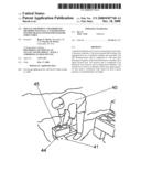
[0019]FIG. 1 in FIGS. 1 A through 1 C are pictures of the general stone leveling float device in the preferred embodiment.
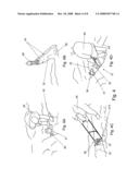
[0020]FIGS. 2 A through 2 D are photographs of the general stone leveling float device in an alternative embodiment.
[0021]FIGS. 3 A and 3 B are close-up photographs of the level indicators on the general stone leveling float devices.
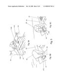
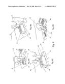
[0022]FIGS. 4 A through 4 D are photographs of the method to use and operate the general stone leveling float devices.
[0023]FIGS. 5 A to 5 C are further steps in installing Unitized Post Tensioned systems after the level has leveled the stone base.
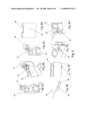
[0024]FIGS. 6 A through 6 D show additional usage details of the level device with Unitized Post Tensioned systems.
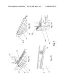
[0025]FIGS. 7 A through 7 D show photographs of the leveled stone base resulting in level and plumb wall systems for the Unitized Post Tensioned systems.
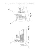
[0026]FIGS. 8 A through 8H provide photographs showing how the notches are placed in the block and then configured with the rest of the Unitized Post Tensioned systems.
DESCRIPTION OF THE DRAWINGS REFERENCE NUMERALS
[0027]The following list refers to the drawings:
TABLE-US-00002 31 General stone leveling sled device with angled plow 31A Alternative stone leveling sled device with flat plow 32 Stone or aggregate 33 Base float structure 33A Flat base float 33B Angular base float 34 Handle 35 Signal receiver unit 36 Electronic level readout 36A Analog slope level readout 37 Angular front to base float 38 Alternative flat front to base float 39 Signal generator 39A Signal beam 40 Operator/worker/installer 41 Linear footer block 41A Cross base footer block 41B Plate receiver pocket 41C Block through aperture for bolt 42 Bolt plate with threaded aperture for bolt 43 Footer trough 44 Foundation block 45 Connector bar 46 Carpenter's level in horizontal position 46A Carpenter's level in vertical position 47 Hand grinder/nibbler 48 Notch 49 Notch filler 50 Wall sill plate 51 Drive tool 52 Indicator level 52A Indicator plumb 53 bolt
DETAILED DESCRIPTION OF PREFERRED EMBODIMENT
[0028]The present invention is a SPECIAL EQUIPMENT AND IMPROVED METHODS TO INSTALL A UNITIZED POST TENSION BLOCK SYSTEM FOR MASONRY STRUCTURES 31,47 (hereinafter called a General Sled leveler 31 for the level or a Nibbler 47 for the new use of the handheld grinder). The new General Sled leveler 31 is comprised of a flat base float 33 featuring an angular 33B or flat 33A front or lead section; a handle 34; and a signal receiver unit 35. The receiver unit 35 is comprised of an electronic level receiver 36 and an analog level indicator 36A. The sled device 31 is used in coordination with a laser signal generator 39 that sends a continuous laser beam 39A out from a given position at a predetermined, set height. A person having ordinary skill in the field of construction, especially with reinforced masonry and concrete structures, appreciates the various parts that may be used to physically permit this SPECIAL EQUIPMENT AND IMPROVED METHODS TO INSTALL A UNITIZED POST TENSION BLOCK SYSTEM FOR MASONRY STRUCTURES 31, 47 to be produced and utilized. The improvement over the existing art is providing a construction system that has many advantages and benefits as stated in the previous section entitled Objects, Advantages, and Benefits.
[0029]There is shown in FIGS. 1 through 3, and FIG. 8 a complete operative embodiment of the General Sled leveler 31 and the Nibbler 47. FIGS. 4 through 8 show the operation of the embodiments. In the drawings and illustrations, one notes well that drawings and sketches demonstrate the general configuration of this invention. The preferred embodiment of the General Sled leveler 31 and Nibbler 47 is comprised of only a few parts as shown. Various important features of these components are also delineated and are described below in appropriate detail for one skilled in the art to appreciate their importance and functionality to the SPECIAL EQUIPMENT AND IMPROVED METHODS TO INSTALL A UNITIZED POST TENSION BLOCK SYSTEM FOR MASONRY STRUCTURES 31,47.
[0030]The accompanying drawings, which are incorporated in and constitute a part of this specification, illustrate embodiments of the General Sled leveler 31 and Nibbler 47 that are preferred. The drawings together with the summary description given above and a detailed description given below serve to explain the principles of the General Sled leveler 31 and Nibbler 47. It is understood, however, that the General Sled leveler 31 and Nibbler 47 are not limited to only the precise arrangements and instrumentalities shown.
[0031]FIG. 1 in FIGS. 1 A through 1 C are pictures of the general stone leveling float 31 device in the preferred embodiment. FIG. 1 A is a side view of the General Sled leveler 31 that shows the leveler 31 is comprised of a flat base float 33 featuring an angular 37 or flat front 38 or lead section; a handle 34; and a signal receiver unit 35. The General Sled leveler 31 is used across stone or aggregate 32. The FIG. 1 B is a back view from the operators perspective with the same elements shown. FIG. 1 C is an isometric like angle view with the angular front 37 and the receiver unit 35 depicted. One skilled in material selection for devices such as this appreciates the plethora of materials that may be used. The float bottom 33 may be a metal such as a steel, galvanized steel, stainless steel or the like. Likewise it may be produced from a wear and corrosion resistant plastic or composite material. The handle 34 may be a metal, plastic or composite and may be configured as a tubular, rectangular or square-like cross-section. The receiver unit 35 is discussed below.
[0032]FIGS. 2 A through 2 D are photographs of the general stone leveling float device 31A in an alternative embodiment. These show the handle 34, the base 33 and the receiver unit 35. However, the lead angle depicts a alternative flat front 38 to the base 33A. Also, FIG. 2 C depicts the receiver unit 35 is comprised of an electronic level readout 36 and an analog level indicator 36A. The sled device is used in coordination with a laser signal generator 39 (not shown here) that sends a continuous laser beam out from a given position at a predetermined, set height. The electronic readout 36 and the analog "ball" level 36A indicates the levelness and slope of the stone 32.
[0033]FIGS. 3 A and 3 B are close-up photographs of the level indicators on the general stone leveling float devices 31. The electronic readout 36 senses the laser signal 39A and permits the flashing LED multi-colored lights to indicate to the operator how level is the stone 32. The analog "ball" level 36A indicates the slope across the breadth of the float 33 to show if all the stone is at the same level condition. In tandem the indicators 36 and 36A permit the operator fast feedback to increase the efficiency and speed of the leveling operation.
[0034]FIGS. 8 A through 8H provide photographs showing how the notches are placed in the block by the Nibbler 47 and then configured with the rest of the Unitized Post Tensioned systems. The operation is discussed below. The new use for the Nibbler 47 is a significant change to common practice by masons and block layers. The Nibbler 47 is a hand held device that cuts and grinds the block notches as compared to using a more remote concrete or masonry saw (away from the immediate wall-site) or using a less accurate hammer and chisel "adjustment". The Nibbler 47 may be electric, battery operated, pneumatic or use other power means. Anticipated is for it to use various types and sizes of abrasive wheels and "cutter" accessories.
[0035]The details mentioned here are exemplary and not limiting. Stated again and well appreciated by one skilled in the art of construction, all the examples of the General Sled leveler 31 and Nibbler 47 may be substituted with other similar configurations and made of various materials and still be within the scope and spirit of this SPECIAL EQUIPMENT AND IMPROVED METHODS TO INSTALL A UNITIZED POST TENSION BLOCK SYSTEM FOR MASONRY STRUCTURES. Other components specific to describing a General Sled leveler 31 and Nibbler 47 may be added as a person having ordinary skill in the field of construction as being obvious from the above described embodiment.
OPERATION OF THE PREFERRED EMBODIMENT
[0036]The new SPECIAL EQUIPMENT AND IMPROVED METHODS TO INSTALL A UNITIZED POST TENSION BLOCK SYSTEM FOR MASONRY STRUCTURES 31 has been described in the above embodiment. The manner of how the device operates is described below. FIGS. 4 through 8 show the operation of the embodiments. One notes well that the description above and the operation described here must be taken together to fully illustrate the concept.
[0037]FIGS. 4 A through 4 D are photographs of the method to use and operate the general stone leveling float devices 31,31A. In FIG. 4 A, the operator 40 places the laser signal generator 39 in the corner of the footer trough 43. He places this on the master or keystone footer. All other block in the foundation will depend on and "take" reference to the prime signal beam 39A from this initial setting. FIG. 4 B shows the operator 40 beginning to level the stone 32 in the footer trough 43 with the General Sled leveler 31 sensing the beam 39A from the laser signal generator 39. FIG. 4 C shows the float 33 with the signal receiver 35 leveling the stone 32. FIG. 4 D shows the operator 40 bringing the General Sled leveler 31 near the corner where the laser generator 39 is placed on the prime footer 44.
[0038]FIGS. 5 A to 5 C are further steps in installing Unitized Post Tensioned systems after the General Sled leveler 31 has leveled the stone and aggregate 32. FIG. 5 A shows the operator 40 placing a threaded bolt plate 42 into a pocket or recess 41B. One sees the similarity and differences of a linear footer 41 with one pocket 42 and a cross footer 41A with two pockets 42. In FIG. 5 B the operator 40 places a linear footer 41 on the stone 32 in the footer trough 43. One may note the through hole 41C where the tendon or bolt will pass through to engage the threads in the threaded plate 42. In FIG. 5 C, the operator continues with another linear footer 41 perpendicular to the first footer 41 and then the initial foundation block 44.
[0039]FIGS. 6 A through 6 D show additional usage details of the level device 31 with Unitized Post Tensioned systems. In these four (4) photographs, the operator begins to add foundation blocks 44 onto the footers 41. The bar or anchor 45 of the Unitized Post Tensioned Masonry System is placed in the recess of the block 44 and assembles the block to the footer 41. This is accomplished when a bolt or tendon 53 connects to the plate 42 and fully secures the foundation block 44 to the footer block 41, below. A pneumatic or electric drive tool 51 is used to turn the bolts 53. In FIG. 6 C, a couple of cross footers 41A are placed for additional strength and stability if needed or desired.
[0040]FIGS. 7 A through 7 D show photographs of the leveled stone base resulting in level and plumb wall systems for the Unitized Post Tensioned systems. The foundation blocks 44 and footers 41, 41A are continued. The bars or anchors 45 are placed onto the block 44. FIG. 7 B shows a nearly complete wall section with the sill plate 50 in place. In FIGS. 7 C and 7 D the accuracy of the building system on this type of leveled foundation of stone 32 is monitored by a carpenter's level in a horizontal 46A and vertical 46B position. The bubble indicator for level 52 is shown in FIG. 7 C and the plumb indicator 52A in FIG. 7 D. Both indicate a very accurate result with the use of the General Sled leveler 31 and the Unitized Post Tensioned Masonry System.
[0041]FIGS. 8 A through 8H provide photographs showing how the notches are placed in the block by the Nibbler 47 and then configured with the rest of the Unitized Post Tensioned systems. The Nibbler 47 creates the notch 48 in the side of the block 44. The Nibbler 47 is small, hand-held and used right at the wall as the blocks are set. No remote cutting with a masonry saw or chiseling is requires since no "wait" time is required for the mortar to set-up. Mortar is not used. FIGS. 8 A through C shows different views of the Nibbler 47 and the foundation block 44. The resultant, clean and precise notch 48 and block 44 is shown in a close-up photograph in FIG. 8 D. This result is not as possible with a hammer and chisel or a remote cut with a masonry saw. FIGS. 8 E and F show a typical filler 49 placed in the notch 48. FIGS. 8 G and 8 H show another handy use where a connector bar 45 or extension bar may be placed through the notch 48 and allow connection to other block 44, mounting of objects or used in many other manners.
[0042]With this description of the detailed parts and operation it is to be understood that the SPECIAL EQUIPMENT AND IMPROVED METHODS TO INSTALL A UNITIZED POST TENSION BLOCK SYSTEM FOR MASONRY STRUCTURES 31,47 is not to be limited to the disclosed embodiment. The features of the General Sled leveler 31 and Nibbler 47 are intended to cover various modifications and equivalent arrangements included within the spirit and scope of the description.
User Contributions:
comments("1"); ?> comment_form("1"); ?>Inventors list |
Agents list |
Assignees list |
List by place |
Classification tree browser |
Top 100 Inventors |
Top 100 Agents |
Top 100 Assignees |
Usenet FAQ Index |
Documents |
Other FAQs |
User Contributions:
Comment about this patent or add new information about this topic:
| People who visited this patent also read: | |
| Patent application number | Title |
|---|---|
| 20140078581 | PHOTOGRAPHING OPTICAL LENS SYSTEM |
| 20140078580 | OPTICAL AMPLIFIER DEVICE |
| 20140078579 | OPTICAL OUTPUT LEVEL CONTROL APPARATUS |
| 20140078578 | FOCUSING ELECTROMAGNETIC RADIATION WITHIN A TURBID MEDIUM USING ULTRASONIC MODULATION |
| 20140078577 | AZO COMPOUND AND INK CONTAINING THE COMPOUND |
Images included with this patent application:
 |  |
 |  |
 |  |
 |  |
| Similar patent applications: | |
| Date | Title |
|---|---|
| 2010-02-04 | System and method to stabilize a prefabricated structure |
| 2012-04-19 | Method of forming flat strip stepped slab floor system of reinforced concrete |
| 2011-07-28 | Wall block and wall block system for constructing walls |
| 2010-04-29 | Structural reinforcement system for concrete structures |
| 2010-08-26 | Special bracket and method for installing a modular fireplace mantel |
| New patent applications in this class: | |
| Date | Title |
|---|---|
| 2012-09-27 | Guide tool and method for laying concrete block |
| 2012-04-26 | Blockout device |
| 2010-03-04 | Grout placement apparatus |
| 2009-10-29 | Brick transport apparatus |
| 2009-10-22 | Safety cap and string snapping apparatus |
| New patent applications from these inventors: | |
| Date | Title |
|---|---|
| 2008-10-23 | Special and improved configurations for unitized post tension block systems for masonry structures |
| Top Inventors for class "Static structures (e.g., buildings)" | |
| Rank | Inventor's name |
|---|---|
| 1 | Darko Pervan |
| 2 | Gregory F. Jacobs |
| 3 | Husnu M. Kalkanoglu |
| 4 | Ronald P. Hohmann, Jr. |
| 5 | Mark Cappelle |