Patent application title: Method for packaging containers automatically
Inventors:
Thomas Mostert (Wuppertal, DE)
IPC8 Class: AB65B1904FI
USPC Class:
053444000
Class name:
Publication date: 2008-12-04
Patent application number: 20080295458
Inventors list |
Agents list |
Assignees list |
List by place |
Classification tree browser |
Top 100 Inventors |
Top 100 Agents |
Top 100 Assignees |
Usenet FAQ Index |
Documents |
Other FAQs |
Patent application title: Method for packaging containers automatically
Inventors:
Thomas Mostert
Agents:
BRINKS HOFER GILSON & LIONE
Assignees:
Origin: CHICAGO, IL US
IPC8 Class: AB65B1904FI
USPC Class:
053444000
Abstract:
The invention relates to a corner guard (1) for box-type containers (4),
such as cases, transport boxes and the like. The corner guard (1)
comprises a caplike corner-protecting element (8) to be fitted externally
over a container corner (2), at least one elastic intermediate corner
element (10) for impact-absorbing arrangement between the
corner-protecting element (8) and the container corner (2) being
provided. Here, the corner-protecting element (8) is to be fastened to
the container corner (2) in such a way that it is disconnected from the
container (4) in terms of elastic impact absorption by way of the
intermediate corner element (10).Claims:
1. A corner guard for box-type containers, such as cases, transport boxes
and the like, comprising a caplike corner-protecting element to be fitted
externally over a container corner at least one elastic intermediate
corner element for providing impact absorption arrangement between the
corner-protecting element and the container corner.
2. The corner guard as claimed in claim 1, further comprising in that the corner-protecting element is connected nonreleaseably to the intermediate corner element to form a unit.
3. The corner guard as claimed in claim 1, further comprising in that the corner-protecting element (8) is connected releaseably, in particular nonpositively and/or positively, to the intermediate corner element (10).
4. The corner guard as claimed in claim 1, further comprising in that the corner-protecting element, together with the intermediate corner element, are fastened nonreleaseably, in particular cohesively, on the container corner.
5. The corner guard as claimed in claim 1, further comprising in that the corner-protecting element, together with the intermediate corner element, can be fastened releaseably in the region of the container corner.
6. The corner guard as claimed in claim 1, further comprising in that the corner-protecting element is provided in an internal corner with a retaining peg onto which the intermediate corner element is mounted or can be mounted by way of a corresponding retaining aperture.
7. The corner guard as claimed in claim 6, further comprising in that the intermediate corner element comprises a sleeve attachment which comprises the retaining aperture and encloses the retaining peg of the corner-protecting element.
8. The corner guard as claimed in claim 8, further comprising retaining means designed in such a way that the corner-protecting element, together with the intermediate corner element, can be fastened to the container corner from the inside of the container.
9. The corner guard as claimed in claim 8, further comprising in that the retaining means is in the form of a retaining screw which can be screwed to the corner-protecting element, in particular to its retaining peg via an elastic pressing element which is adapted to be arranged in the inside of the container, in such a way that the corner-protecting element is disconnected from the container in terms of elastic impact absorption by way of the intermediate corner element and the pressing element.
10. The corner guard as claimed in claim 9, further comprising in that the elastic pressing element is in butting connection with the intermediate corner element in certain regions, in particular in a positively engaging manner via corresponding contoured and negatively contoured surfaces.
11. The corner guard as claimed claim 1 further comprising in that the corner-protecting element and also the intermediate corner element each have three wall sections which are each arranged at right angles to one another and which are each to be arranged parallel to one of three container walls adjoining in the region of the container corner.
12. The corner guard as claimed in claim 1, further comprising in that the corner-protecting element has externally a partially spherical surface with three flat areas which are each at right angles to one another.
13. The corner guard as claimed in claim 1, further comprising in that the corner-protecting element consists of a relatively dimensionally stable or hard elastic, preferably fiber-reinforced, plastic, in particular of a polyurethane elastomer or of polyamide (PA).
14. The corner guard as claimed in claim 1, further comprising in that at least one of the intermediate corner element or the inner pressing element consists of a soft elastic polyurethane (PU) plastic having a Shore A hardness approximately in the range from 50 to 60, preferably approximately 55.
15. A container comprising a case in the form of a transport box or the like, and at least one corner guard fastened in the region of a container corner including a caplike corner-protecting element to be fitted externally over the container corner, at least one elastic intermediate corner element for providing impact-absorption between the corner-protecting element and the container corner.
16. The container as claimed in claim 15 having eight container corners, further comprising up to eight associated corner guards.
17. The container as claimed in claim 15, further comprising in that the corner guard is fastened in the region of a container corner opening by screwing the retaining screw to the corner-protecting element from the inside of the container, using an elastic pressing element in such a way that edges of the container corner opening are clamped between the elastic intermediate corner element and the elastic pressing element.
18. The container as claimed in claim 15, further comprising in that the wall sections of the intermediate corner element lie flat between the container walls and the wall sections of the corner-protecting element.
Description:
CROSS REFERENCE TO RELATED APPLICATION
[0001] This application claims priority to German Utility Model 203 05 778.3, filed Apr. 10, 2003 and PCT/EP2004/003501, filed Apr. 2, 2004.
FIELD OF THE INVENTION
[0002] The present invention relates to a corner guard for box-type containers, such as cases, transport boxes and the like, of the type having a caplike corner-protecting element to be fitted externally over a container corner.
[0003] Furthermore, the invention also relates to a container provided with at least one (and up to eight) such corner guard or guards.
BACKGROUND AND SUMMARY OF THE INVENTION
[0004] Corner guards for containers are known; they commonly consist of a sheet-metal material having three wall sections which are each at right angles to one another and are intended to bear on three container walls adjoining a container corner, the wall sections usually being screwed, riveted or adhesively bonded to the container walls from outside. Such corner guards are intended to provide the container corners with a certain degree of protection from impact-related damage. However, impact-related damage is frequently caused to the contents of the container during practical use, especially if sensitive equipment or items form the contents.
[0005] The object on which the present invention is based is to improve a corner guard of the aforementioned type in such a way that a container equipped with such a guard is not only protected itself from impact-related damage in the corner region, but it is also possible to significantly reduce impact-related damage to the container contents.
[0006] This is achieved according to the invention by means of at least one elastic intermediate corner element for impact-absorbing arrangement between the corner-protecting element and the container corner. According to the invention, the corner-protecting element is thus completely elastically disconnected from the container by way of the intermediate corner element, with the result that impacts acting against the corner-protecting element from outside cannot be transmitted directly to the container but are absorbed elastically by the intermediate element, the impact energy being damped (consumed) by elastic deformations. As a consequence, the respective container contents are also advantageously protected from impacts, which means that a container equipped with corner guards according to the invention is optimally suitable for accommodating impact-sensitive items and equipment.
[0007] For reasons in particular of manufacturing, handling and assembly it is advantageous if, prior to being fastened to the respective container, the corner-protecting element has already been connected to the intermediate corner element to form a unit. For this purpose, a nonreleaseable, for example cohesive, connection is possible, for example by adhesive bonding, welding or else by integral production from plastic as a two-component molding. However, a nonpositive and/or positive connection, in particular a plug-type connection, is also advantageous since use can thus be optionally made of intermediate corner elements which differ in terms of their elasticity and impact-absorbing properties. Moreover, there is also the possibility of simple replacement at any time.
[0008] The corner guard according to the invention can likewise be fastened nonreleaseably, for example by adhesive bonding, to or on the respective container corner. However, the corner-protecting element, together with the intermediate corner element, can preferably be fastened releaseably in the region of the container corner. In a further preferred refinement, this fastening operation is carried out in the region of a container corner opening from the inside of the container, in particular by means of a retaining screw which engages in a retaining hole in the corner-protecting element, preferably by means of an additional inner elastic pressing element in such a way that the corner-protecting element is disconnected from the container in terms of elastic impact absorption by way of the intermediate corner element and the pressing element. The edges of the container walls adjoining the corner opening are thus retained by being clamped exclusively between the elastic components of the corner guard according to the invention, with the result that the corner-protecting element is thereby retained elastically (elastically suspended) on the container.
[0009] Further advantageous design features of the invention are contained in the subclaims and the description which follows.
BRIEF DESCRIPTION OF THE INVENTION
[0010] The invention will be explained more precisely with the aid of a preferred exemplary embodiment illustrated in the drawing, in which:
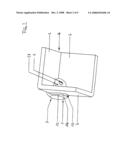
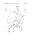
[0011] FIG. 1 shows a perspective partial view of a container in the region of a container corner which is provided with a corner guard according to the invention,
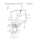
[0012] FIG. 2 shows a perspective view of the arrangement according to FIG. 1 from the inside of the container,
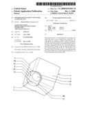
[0013] FIG. 3 shows a perspective exploded representation pertaining to FIG. 1 (view from the outside of the container), and
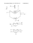
[0014] FIG. 4 shows a perspective exploded representation pertaining to FIG. 2 (from the inside of the container).
DETAILED DESCRIPTION OF THE INVENTION
[0015] A corner guard 1 according to the invention is fastened in the region of a container corner 2 (FIG. 3) to a container 4, only part of which has been represented. The container 4 takes the form of a case, transport box or the like, three container walls 6, usually at right angles to one another, in each case adjoining one another in the region of each container corner 2.
[0016] The corner guard 1 comprises a caplike corner-protecting element 8 to be fitted externally over the respective container corner 2 and also, according to the invention, an elastic intermediate corner element 10 for impact-absorbing arrangement between the corner-protecting element 8 and the container corner 2.
[0017] According to FIGS. 3 and 4, the corner-protecting element 8 and also the intermediate corner element 10 comprise three respective wall sections 12 and 14 which are each arranged at right angles to one another and are each to be arranged parallel to one of the three container walls 6 adjoining in the region of the container corner 2, and when in the fitted state on the container corner 2 as shown in FIGS. 1 and 2, the wall sections 14 of the intermediate corner element 10 lie flat between the container walls 6 and the wall sections 12 of the corner-protecting element 8.
[0018] In the preferred embodiment represented, the corner-protecting element 8 is connected releaseably to the intermediate corner element 10, in particular in a nonpositive and/or positive manner by means of a plug-type connection. Furthermore, the corner-protecting element 8, together with the intermediate corner element 10, can also be fastened releaseably in the region of the container corner 2.
[0019] Alternatively, however, provision may also be made for the corner-protecting element 8 to be connected nonreleaseably to the intermediate corner element 10 to form a unit. Furthermore, the corner-protecting element 8, together with the intermediate corner element 10, may also be fastened nonreleaseably on the container corner 2, for example by adhesive bonding.
[0020] In the preferred embodiment, the connection of the components requires making provision for the corner-protecting element 8 to be provided in an internal corner 16, which is enclosed by the wall sections 12, with a retaining peg 18 extending at a diagonal angle of approximately 45° to all the wall sections 12 (see FIG. 4), onto which peg the intermediate corner element 10 can be mounted by way of a corresponding retaining aperture 20. A frictional positive locking engagement is preferably provided here. In addition, the intermediate corner element 10 preferably comprises a sleeve attachment 22 which comprises the retaining aperture 20 and virtually completely encloses the retaining peg 18 of the corner-protecting element 8, with the result that an elastic disconnection of the corner-protecting element 8 from the container 4 is ensured in this region too. Provision is preferably also made here for the corner-protecting element 8, together with the intermediate corner element 10, when in the mounted state on the container corner 2, to be retained by retaining means from the inside of the container in the region of a container corner opening 24 (see FIGS. 3 and 4). For this purpose, the retaining peg 18 of the corner-protecting element 8, together with the sleeve attachment 22 of the intermediate corner element 10, protrudes through the container corner opening 24, a retaining screw 26 being screwed to the retaining peg 18 in the inside of the container. This is carried out particularly advantageously by means of an inner elastic pressing element 28 in such a way that the corner-protecting element 8 is disconnected from the container 4 in terms of elastic impact absorption by way of the intermediate corner element 10 and the pressing element 28, which entails the container walls 6 being contacted exclusively between the elastic components 10 and 28. As is indicated in FIG. 4, the elastic pressing element 28 here is in butting connection with the intermediate corner element 10 through the container corner opening 24, preferably via corresponding contoured and negatively contoured surfaces having a positive engagement. The container corner opening 24 here is formed by rectangular or rounded cutouts in each container wall 6, with the result that the actual corner of the container 4 is cut away.
[0021] In the embodiment represented, the corner-protecting element 8 has externally a partially spherical surface 30 with three flat areas 32 which are each at right angles to one another. Reference should be made particularly to FIG. 1 in this regard. This embodiment may thus also be referred to as a spherical corner guard.
[0022] The corner-protecting element 8 advantageously consists of a relatively dimensionally stable or hard elastic, preferably fiber-reinforced, plastic. A polyurethane elastomer, as can be obtained for example under the registered trade mark Desmopan, or a polyamide (PA), for example PA6 GF30, is particularly suitable. By contrast, the intermediate corner element 10 may consist of a soft elastic plastic having a Shore A hardness approximately in the range from 50 to 60, preferably approximately 55. A polyurethane (PU) is particularly suitable here. The hardness here may also be selected to be harder or softer to suit the size and the weight of the respective container 4 and the damping properties desired therefor. To ensure good impact absorption here, the effective material thickness of the intermediate corner element 10 should be at least 4 to 5 mm in every region between the container 4 and the corner-protecting element 8. This consequently also applies to the wall sections 14 which should consequently have a thickness of at least approximately 5 mm. The thickness may also be tailored to the size and the weight of the container 4 in order to achieve optimum damping properties.
[0023] The inner pressing element 28 advantageously consists of a material which is identical to that of the intermediate corner element 10.
[0024] The invention also relates to the overall container 4, the eight corners 2 of which container are equipped with up to eight associated corner guards 1 according to the invention.
[0025] While the above description constitutes the preferred embodiment of the present invention, it will be appreciated that the invention is susceptible to modification, variation and change without departing from the proper scope and fair meaning of the accompanying claims.
User Contributions:
comments("1"); ?> comment_form("1"); ?>Inventors list |
Agents list |
Assignees list |
List by place |
Classification tree browser |
Top 100 Inventors |
Top 100 Agents |
Top 100 Assignees |
Usenet FAQ Index |
Documents |
Other FAQs |
User Contributions:
Comment about this patent or add new information about this topic:
Images included with this patent application:
 |  |
 |  |
 |