Patent application title: Vaccum Cleaner Device
Inventors:
Lennart Olsson (Sandared, SE)
Conny Loftander (Kungsbacka, SE)
IPC8 Class: AA47L924FI
USPC Class:
154151
Class name: Machines with air blast or suction nozzle
Publication date: 2008-12-04
Patent application number: 20080295282
Inventors list |
Agents list |
Assignees list |
List by place |
Classification tree browser |
Top 100 Inventors |
Top 100 Agents |
Top 100 Assignees |
Usenet FAQ Index |
Documents |
Other FAQs |
Patent application title: Vaccum Cleaner Device
Inventors:
Lennart Olsson
Conny Loftander
Agents:
WRB-IP LLP
Assignees:
Origin: ALEXANDRIA, VA US
IPC8 Class: AA47L924FI
USPC Class:
154151
Abstract:
A vacuum cleaner device has a nozzle which, via a pivotal connection, is
connectable to a lower end of a vacuum cleaner pipe which, at its upper
end via a vacuum cleaner hose is connectable to a vacuum cleaner. The
vacuum cleaner pipe has inner and outer parts which are longitudinally
displaceable in relation to one another, and a joint whose pivot axis is
parallel with the pivot axis of the connection. The joint of the vacuum
cleaner pipe is disposed on the inner section and, for locking of the
joint, is insertable in the outer section.Claims:
1. A vacuum cleaner device comprising a vacuum cleaner nozzle with a
connection to one end of a vacuum cleaner pipe whose opposite end is
connectable via a vacuum cleaner hose to a vacuum cleaner, the connection
being pivotal and the vacuum cleaner pipe having inner and outer parts
which are mutually longitudinally displaceable in relation to one another
and a joint with a hose, wherein the joint is disposed on the inner
section and is insertable in the outer section for locking of the joint.
2. The vacuum cleaner device as claimed in claim 1, wherein the pivot axes of the connection and the joint are substantially parallel with one another.
3. The vacuum cleaner device as claimed in claim 1, wherein the connection includes a connection tube for interconnection with the vacuum cleaner pipe, the connection tube being substantially straight and non-rotatably secured about its longitudinal axis in the nozzle.
4. The vacuum cleaner device as claimed in claim 1, wherein the outer section is, via the vacuum cleaner hose, connectable to the vacuum cleaner and the inner section has an anchorage for cooperation with the connection to the vacuum cleaner nozzle.
5. The vacuum cleaner device as claimed in claim 1, wherein the inner section includes an extension tube and an upper tube section, the hose being disposed to bridge across a distance between them.
6. The vacuum cleaner device as claimed in claim 5, wherein the hose has, on its inside, a smooth surface; and the end edges of the hose form a gentle transition from the slightly larger diameter of the inner tube section to the slightly smaller diameter of the hose.
7. The vacuum cleaner device as claimed in claim 5, wherein the extension tube and the upper tube section display anchorages which are pivotally connected to one another.
8. The vacuum cleaner device as claimed in claim 5, wherein the extension tube and the upper tube section display anchorages which are pivotally connected to one another via linkage arm sections.
9. The vacuum cleaner device as claimed in claim 5, wherein the hose is releasable.
10. The vacuum cleaner device as claimed in claim 2, wherein the connection includes a connection tube for interconnection with the vacuum cleaner pipe, the connection tube being substantially straight and non-rotatably secured about its longitudinal axis in the nozzle.
11. The vacuum cleaner device as claimed in claim 2, wherein the inner section includes an extension tube and an upper tube section, the hose being disposed to bridge across a distance between them.
12. The vacuum cleaner device as claimed in claim 11, wherein the hose has, on its inside, a smooth surface; and the end edges of the hose form a gentle transition from the slightly larger diameter of the inner tube section to the slightly smaller diameter of the hose.
13. The vacuum cleaner device as claimed in claim 11, wherein the extension tube and the upper tube section display anchorages which are pivotally connected to one another.
14. The vacuum cleaner device as claimed in claim 11, wherein the extension tube and the upper tube section display anchorages which are pivotally connected to one another via linkage arm sections.
15. The vacuum cleaner device as claimed in claim 2, wherein the hose is releasable.
16. The vacuum cleaner device as claimed in claim 3, wherein the inner section includes an extension tube and an upper tube section, the hose being disposed to bridge across a distance between them.
17. The vacuum cleaner device as claimed in claim 11, wherein the hose has, on its inside, a smooth surface; and the end edges of the hose form a gentle transition from the slightly larger diameter of the inner tube section to the slightly smaller diameter of the hose.
18. The vacuum cleaner device as claimed in claim 11, wherein the extension tube and the upper tube section display anchorages which are pivotally connected to one another.
19. The vacuum cleaner device as claimed in claim 11, wherein the extension tube and the upper tube section display anchorages which are pivotally connected to one another via linkage arm sections.
20. The vacuum cleaner device as claimed in claim 4, wherein the inner section includes an extension tube and an upper tube section, the hose being disposed to bridge across a distance between them.
Description:
BACKGROUND AND SUMMARY
[0001]The present invention relates to a vacuum cleaner device which comprises a vacuum cleaner nozzle with a connection to one end of a vacuum cleaner pipe whose opposite end is connectable via a vacuum cleaner hose to a vacuum cleaner, the connection being pivotal and the vacuum cleaner pipe having inner and outer, mutually longitudinally displaceable parts and a joint with a hose.
[0002]It is a known fact that, using a standard vacuum cleaner hose with a standard shaft, it is very difficult to get at and vacuum clean a distance in beneath low furniture. The most prevalent solution is that the vacuum cleaner pipe displays an angled connection to the vacuum cleaner nozzle and that this can be rotated so that the vacuum cleaner pipe can be laid parallel along the floor. When the vacuum cleaner pipe is parallel with the floor, the user of the vacuum cleaner must bend down to floor level in order to be able to steer the nozzle under furniture or the like, which is extremely fatiguing among other things for the back. If attempts are made to vacuum cleaner under an item of furniture as far as is possible without laying the vacuum cleaner pipe down, there is a very great risk of damaging the lower edge of the furniture when the upright vacuum cleaner pipe strikes the edge of the furniture. To vacuum cleaner up on the top level of a tall item of furniture from floor level using existing constructions of vacuum cleaner pipes is totally impossible. In order to manage this, a chair or ladder must be used so that the user of the vacuum cleaner can hold the vacuum cleaner pipe parallel with the upper surface of the furniture.
[0003]All of these drawbacks have been obviated by means of the present invention. By means of an elbow joint that can be bent through 180°, the user of the vacuum cleaner can, with the elbow joint in a position at about 90°, stand upright and at the same time, because of the axial lateral rigidity of the elbow joint, maintain full control over guiding the nozzle under a low item of furniture. The nozzle, with a gentle reciprocal movement, can be moved back and forth. When vacuum cleaning up on a cupboard, the nozzle can, thanks to the elbow joint, just as easily be moved back and forth in analogy with vacuum cleaning under furniture. In normal vacuum cleaning of floors, the extension tube and the elbow joint are telescopically retracted in the vacuum cleaner shaft so that a normal, completely rigid vacuum cleaner shaft is obtained. In the protracted position, there will be obtained a rigid, straight section which, by the intermediary of the elbow joint, is connected to the vacuum cleaner shaft. The protractible section together with the elbow joint has a length which as good as corresponds to the length of an existing vacuum cleaner shaft, which is sufficient for normal use. For special purposes, other lengths can naturally be manufactured.
[0004]SE 9600650-7 discloses a construction in a vacuum cleaner pipe with a joint formed by a hose or bellows which can be locked by means of a movable collar running along the vacuum cleaner pipe. The movable collar locks two pipe sections included in the vacuum cleaner pipe in relation to one another in a rigid position.
[0005]The drawback inherent in this design and construction is that both pipe sections of the vacuum cleaner pipe are fixed in length and are not per se telescopic in relation to one another, since their pipe dimension or diameter is the same.
[0006]It is desirable to design the device described by way of introduction such that this obviates the drawbacks inherent in the prior art technology. In particular, it is desirable to design the vacuum cleaner device so that it simplifies vacuum cleaning under low items of furniture and up on tall items of furniture.
[0007]According to an aspect of the invention, a vacuum cleaner device described by way of introduction is characterised in that the joint is disposed on the inner section and is insertable in the outer section for locking of the joint.
BRIEF DESCRIPTION OF THE ACCOMPANYING DRAWINGS
[0008]The present invention will now be described in greater detail hereinbelow, with reference to the accompanying Drawings. In the accompanying Drawings:
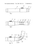
[0009]FIG. 1 shows the device according to the present invention inserted in the vacuum cleaner shaft or pipe;
[0010]FIG. 2 shows the device according to the present invention wholly withdrawn out of the vacuum cleaner shaft or pipe;
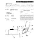
[0011]FIG. 3 shows an elbow joint included in the device according to the present invention bent at approximately 80°;
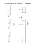
[0012]FIGS. 4a,b,c show a hose included in the joint with a number of different embodiments of rigidifying means which prevent the hose from being compressed;
[0013]FIG. 5 shows a variation of the present invention with a sleeve slid over the joint;
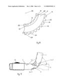
[0014]FIG. 6 shows anchorages with cogs included in the joint;
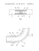
[0015]FIG. 7 shows a detail of the hose with the flanks of externally disposed annular rigidifying means, on the one hand on an unbent section of the hose and on the other at a bend of approx. 90°;
[0016]FIG. 8 shows a 90° bending of the hose where the inner side of the bend is compressed and the outer side is expanded; and
[0017]FIG. 9 shows a simplified variation where the anchorages in the joint are pivotally connected direct to the anchorages without interjacent linkages.
DETAILED DESCRIPTION
[0018]In its most generic form, the present invention is based on the concept that the vacuum cleaner device is to have two joints whose pivot axes are substantially parallel with one another and where the one joint is disposed on or in connection with a vacuum cleaner nozzle included in the vacuum cleaner device, while the other is to be disposed on a vacuum cleaner pipe whose upper end is, via a vacuum cleaner hose, connectable to a vacuum cleaner. As a result of this arrangement, the vacuum cleaner pipe can, on vacuum cleaning under a low item of furniture, be bent so that its lower section lies along the floor while its upper section connected to the vacuum cleaner hose extends up from the floor so that it may readily be operated by a standing user.
[0019]In order to permit vacuum cleaning in a conventional manner, the joint of vacuum cleaner pipe is lockable in the straight position. Further, it is rigid in all other directions than about its own pivot axis when it is "open".
[0020]The vacuum cleaner nozzle has a connection for cooperation with the lower end of the vacuum cleaner pipe and has a connection pipe for interconnection with the vacuum cleaner pipe or an anchorage 11 disposed thereon. The connection pipe is, unlike in the prior art technology, substantially straight and non-rotatably fixed about its longitudinal axis in the nozzle. On the other hand, it is pivotal within a sector of 75° to 90° from a position approximately parallel with floor on which the nozzle stands in normal working position, to an upright position.
[0021]According to the present invention, the vacuum cleaner pipe is, as was mentioned above, provided with a single elbow joint 25 or an elbow joint 12 with linkage arms 8 and 9, which permit the vacuum cleaner pipe to bend reciprocally through more than 180°, it being readily possible at a bending angle of about 90° to get at planar surfaces which are located low down or high up. The present invention may be designed in such a manner that the entire device including extension tube 2 together with elbow joint section 12 and the upper section 1 of the elbow joint can be inserted into an existing vacuum cleaner shaft 10, where the device according to the invention may be fixedly locked by a locking device 15 in the vacuum cleaner shaft 10 belonging to the existing vacuum cleaner. Hereby, the joint is locked in the straight position. Similarly, the device according to the present invention is prevented from being drawn out of the vacuum cleaner shaft 10 by the arrest means 13 and 14. The nozzle belonging to the vacuum cleaner shaft 10 can be mounted direct on the nozzle fitting 11 of the extension tube 2.
[0022]Also for certain types of vacuum cleaners which lack a telescopic vacuum cleaner shaft 10, it is possible to utilise the present invention and at the same time obtain the function of a rigid vacuum cleaner shaft. Instead of telescopically inserting the device in a vacuum cleaner shaft, a sleeve 20 can be slid over the elbow joint section 12 in order to lock the joint in a straight position. The sleeve 20 is locked using a locking device 15 both when it is slid on the elbow joint 12 and when it is slid off.
[0023]In one embodiment of the present invention, it consists of or comprises two tube sections 1 and 2 joined together with two linkage arms 8 and 9 which are pivotally secured in the anchorages 6 and 7 in the tubular upper section 1 of the elbow joint 12. The union of the joints is carried out by means of an element which may, for example, be a rivet, screw or the like. The linkage arms 8 and 9 are also pivotally connected to the anchorages 4 and 5 of the extension tube 2. A hose connection 3 goes from the extension tube 2 through the elbow joint section 12 to the tubular upper section 1 of the elbow joint 12. The hose connection 3 is fixed airtight to both of the tube sections 1 and 2, for example by gluing or that the hose 3 has been provided with one or more external annular ridges that fit into corresponding grooves on the inside of both of the tubes. By employing the linkage arms 8 and 9, the bending radius of the hose connection 3 will be increased, which contributes in reducing the risk of the hose connection 3 being folded over or creased.
[0024]The hose 3 may further wholly or partly be removable for facilitating cleaned of the hose 3 when unsuitable foreign matter has accumulated and clogged the hose 3. The hose 3 may be removable in one or both of its ends.
[0025]In certain cases, it may be advantageous always to have the bending centre of the elbow joint section 12 fixed so that it cannot be displaced towards either of the tube sections 1 and 2. This can be achieved in that both of the linkage arms 8 and 9 are provided in both ends with cogs 19 which are constantly in mesh, on the one hand, in both anchorages 4 and 5 of the extension tube 2 and, on the other hand in both anchorages 6 and 7 of the tube section 1.
[0026]The tube sections 1 and 2 being united by means of the two linkage arms, the risk will be avoided that the hose 3 on bending will have too tight a radius which could cause the hose 3, in relation to the bending centre of the elbow joint section 12, to be radially compressed so that the through flow area will be constricted, with a risk of clogging which may entail a loss of suction. In that the hose 3 is designed with annular, relatively close external rigidifying ridges 16, and also that the hose 3 is prevented by the two linkage arms 8 and 9 from expanding axially in relation to the bending centre of the elbow joint, the tendency for compression of the hose 3 will be further reduced, with the result that the flow resistance for the air current will be extremely slight.
[0027]The best results for a good through flow through the elbow joint section 12 are attained when the hose 3 has a completely smooth inside surface and where the end edges 18 of the hose 3 form a gentle transition from the slightly larger diameter of the tube sections 1 and 2 to the slightly smaller diameter of the hose 3 so that turbulence is greatly reduced. The property of the material from which the hose 3 is manufactured is, in order to attain the desired bending properties of the hose 3, decisive for how the external rigidifying ridges 16 and their interjacent spaces must be designed. In a correctly balanced relationship between material properties and the size of the ridges 16 and their interspaces, an almost completely smooth inner surface will be obtained on bending of the hose 3. This implies then that clogging is eliminated. The width of and the interspaces between the external rigidifying ridges 16 is hence determined by the material from which the hose 3 is manufactured in order to obtain as gentle a curvature as possible with the smoothest possible inner surface. With the correctly adapted width of the external rigidifying homogeneous ridges 16 as well as the size of the interspaces, both in width and depth, and with optimum design of the ridges 16 and the flanks 21 of their interspaces, it is possible, at bending angles of more than 100°, to obtain an as good as completely smooth inner surface in the hose 3 at the same time as the bending centre 24 of the hose 3 is as good as always located closely approximating the ideal position. The flanks 21 can, for facilitating a bending of the hose 3, be designed in trapezoidal form where the upper region 22 of the ridge 16 is narrower than the base 23, which then results in the hose 3 more readily being able to be bent when the ridges, on that side of the hose bend which is located most proximal the bending centre 24 of the hose 3, are not exposed to as great a compression in the axial direction of the hose, since the flank upper portion 22 of the ridge 16 will have more room. At a bending of about 100°, depending on the rigidity and elasticity of the hose material, the upper portions 22 on the side which is most proximal the bending centre 24 of the hose 3 will meet at the same time as the interspaces of the ridges 16 are compressed together at the same time as, on that side of the hose 3 which is most distal from the bending centre 24 of the hose 3, the interspaces of the ridges 16 are greatly stretched out.
[0028]In certain contexts, on transport in the hose 3 of substances which could be aggressive, a material for the hose 3 must be selected which withstands this substance. This hose material may perhaps be so soft that it is incapable, despite the external rigidifying ridges 16 and their interspaces, of holding the bending centre of the hose 3 in the proximity of the ideal position. This ideal position can then be positively created in that the linkage arms 8 and 9 are provided in both of their ends with cogs 19 which are in constant mesh in the anchorages 4 and 5 of the extension tube 2 as well as in the anchorages 6 and 7 of the tube connection 1. The bending centre of the elbow joint 12 will then always lie in the centre point of the linkage arms 8 and 9.
[0029]On certain occasions, it may be necessary to use a hose 3 which is designed as a bellows 17 because of the fact that the hose 3 is exposed to aggressive substances and must then be manufactured from a material resistant to such a substance which is not ideal as regards rigidity and elasticity and cannot, therefore, be designed with the rigidifying ridges 16 and their interspaces. When such a hose 3 designed as a bellows 17 is used, the insides of the hose 3 will be greatly folded and creased and then display a much higher through-flow resistance with a consequential considerably greater risk of clogging 4.
[0030]For certain purposes, for example for a more economical variation where the requirement for gentle and symmetric bending of the hose 3 is not so critical, the linkage arms 8 and 9 can be dispensed with and the anchorages 4 and 5 be directly pivotally connected to the anchorages 6 and 7 by means of some known joining element, in which event a joint with a smaller bending radius will be obtained. This joint is also capable of bending a total of more than 180° and where a bending of the elbow joint section 25 on a bending about 90° in accordance with the previous description for joints with linkage arms 8 and 9, also this simplified embodiment provides the possibility of getting under low items of furniture without the shaft 10 of the vacuum cleaner needing to be laid down parallel with the floor or requiring the use of a chair or a ladder to gain access, for example to tall items of furniture. The possibility of being able to insert the upper section of the elbow joint 25 in an existing vacuum cleaner shaft remains unchanged.
User Contributions:
comments("1"); ?> comment_form("1"); ?>Inventors list |
Agents list |
Assignees list |
List by place |
Classification tree browser |
Top 100 Inventors |
Top 100 Agents |
Top 100 Assignees |
Usenet FAQ Index |
Documents |
Other FAQs |
User Contributions:
Comment about this patent or add new information about this topic:
Images included with this patent application:
 |  |
 |  |
 |
| Similar patent applications: | |
| Date | Title |
|---|---|
| 2013-09-12 | Combination broom vacuum cleaning device |
| 2013-09-12 | Vacuum cleaner and vacuum cleaner system |
| 2010-09-23 | Vacuum cleaner sensor |
| 2010-12-09 | Vacuum cleaner head |
| 2011-06-09 | Vacuum cleaner nozzle |
| New patent applications in this class: | |
| Date | Title |
|---|---|
| 2016-06-30 | Vacuum attachment device |
| 2016-06-02 | Floor tool for a vacuum cleaner |
| 2016-03-31 | Vacuum cleaner |
| 2015-12-03 | Crack and crevice cleaning tools and attachments therefor |
| 2015-05-14 | Vacuum cleaner head |
| Top Inventors for class "Brushing, scrubbing, and general cleaning" | |
| Rank | Inventor's name |
|---|---|
| 1 | Wayne Ernest Conrad |
| 2 | Xavier Boland |
| 3 | Helmut Depondt |
| 4 | Robert Moskovich |
| 5 | James Dyson |