Patent application title: IGNITION DEVICE FOR A GAS STOVE
Inventors:
Chien-Chou Chen (Tainan City, TW)
Chien-Chou Chen (Tainan City, TW)
IPC8 Class: AF24C308FI
USPC Class:
126 39 R
Class name: Cooking liquid or gaseous fuel gas
Publication date: 2008-11-27
Patent application number: 20080289618
Inventors list |
Agents list |
Assignees list |
List by place |
Classification tree browser |
Top 100 Inventors |
Top 100 Agents |
Top 100 Assignees |
Usenet FAQ Index |
Documents |
Other FAQs |
Patent application title: IGNITION DEVICE FOR A GAS STOVE
Inventors:
Chien-Chou CHEN
Agents:
RABIN & Berdo, PC
Assignees:
Origin: WASHINGTON, DC US
IPC8 Class: AF24C308FI
USPC Class:
126 39 R
Abstract:
An ignition device is mounted in a stove base of a gas stove and has a gas
valve assembly, an electronic igniter and a triggering knob. The gas
valve assembly is mounted in the stove base and has a gas valve with a
valve nozzle and an extending tube extending toward multiple elongated
burners mounted in the stove base and having multiple gas holes formed
through the extending tube at intervals. When the triggering knob is
pressed and turned, gas is simultaneously ejected from the gas holes and
mixes with gas simultaneously ejected the burners to form a continuous
gas cloud, and the electronic igniter simultaneously produces sparkles to
ignite gas discharged from the valve nozzle to generate a starting flame
tongue instantly extending toward and igniting the gas cloud to ignite
all the burners to effectively reduce leakage of gas.Claims:
1. An ignition device for a gas stove having a stove base with a burner
chamber formed in the stove base and having an inner surface, the
ignition device comprisinga gas valve assembly being adapted to be
mounted in the stove base and havinga gas valve havinga distal end;an
inlet;an outlet;a mounting hole; anda valve nozzle being formed on and
protruding from the distal end of the gas valve to form a discharge path
and spraying gas;an inlet tube being connected to the inlet of the gas
valve; andan extending tube being adapted to be mounted on the inner
surface of the burner chamber, being connected to the mounting hole of
the gas valve, communicating with and receiving gas from the gas valve
and havingmultiple gas holes being formed through the extending tube at
intervals;an electronic igniter being mounted near the valve nozzle and
having an electrode extending into the discharge path of the valve
nozzle;a flame restrictor being mounted near the electrode of the
electronic igniter partially around the discharge path of the valve
nozzle; anda triggering knob being adapted to be mounted on the stove
base, being connected electrically to the electronic igniter and being
connected to and operating the gas valve to selectively open and close
the gas valve.
2. A gas stove comprisinga stove base havinga burner chamber being formed in the stove base and having an inner surface;multiple elongated burners being mounted in the burner chamber in the stove base at intervals, and each elongated burner having two opposite narrow ends and a gas inlet;an outlet tube being mounted in the burner chamber and havingan outer surface; andmultiple gas nozzles being mounted in the outer surface of the outlet tube and aligning respectively with the gas inlets of the elongated burners; andan ignition device being mounted in the stove base and havinga gas valve assembly being mounted in the stove base adjacent to the elongated burners and havinga gas valve havinga distal end;an inlet;an outlet being connected to the outlet tube;a mounting hole; anda valve nozzle being formed on and protruding from the distal end of the gas valve, extending toward the elongated burners perpendicularly to the elongated burners to form a discharge path and spray gas toward the elongated burners;an inlet tube being connected to the inlet of the gas valve; andan extending tube being mounted on the inner surface of the burner chamber in the stove base, connected to the mounting hole of the gas valve, communicating with and receiving gas from the gas valve, extending perpendicularly to the elongated burners adjacent to one of the narrow ends of the elongated burners and havinga rear section; andmultiple gas holes being formed through the extending tube at intervals shorter than that between adjacent elongated burners;an electronic igniter being mounted near the valve nozzle and havingan electrode extending into the discharge path of the valve nozzle;a flame restrictor being mounted near the electrode of the electronic igniter partially around the discharge path of the valve nozzle; anda triggering knob being mounted on the stove base, connected electrically to the electronic igniter and connected to and operating the gas valve to selectively open and close the gas valve.
3. The gas stove as claimed in claim 2, wherein the gas holes are formed within the rear section of the extending tube and are away from an elongated burner closest to the gas valve.
Description:
BACKGROUND OF THE INVENTION
[0001]1. Field of the Invention
[0002]The present invention relates to an ignition device for a gas stove, and more particularly to an ignition device that can rapidly ignite multiple separated burners of the gas stove to effectively reduce leakage of gas.
[0003]2. Description of Related Art
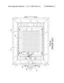
[0004]With reference to FIG. 6, a conventional gas stove (40) has a stove base (41), a rectangular burner (42), an outlet tube (54) and an ignition device (not numbered).
[0005]The rectangular burner (42) is mounted in the stove base (4 1) and has a top surface (not numbered) and a gas orifice array (not numbered). The gas orifice array is formed in the top surface of the rectangular burner (42) and has multiple gas orifices (not numbered). The gas orifices are arranged in parallel lines.
[0006]The outlet tube (54) is mounted in the stove base (41) and is connected to the rectangular burner (42) to deliver gas to the rectangular burner (42). The gas passes through the outlet tube (54) and escapes from the gas orifices.
[0007]The ignition device is mounted in the stove base (41) and has a gas valve assembly (60), an electronic igniter (52), a flame restrictor (53) and a triggering knob (51). The gas valve assembly (60) is mounted in the stove base (41) adjacent to the rectangular burner (42) and has a gas valve (61) and an inlet tube (62). The gas valve (61) has a distal end (not numbered), an inlet (not numbered), an outlet (not numbered) and a nozzle (611). The outlet of the gas valve (61) is connected to and communicates with the outlet tube (54). The nozzle (611) is formed on and protrudes from the distal end of the gas valve (61) toward the rectangular burner (42) perpendicular to the lines of gas orifices to form a discharge path. The inlet tube (62) is connected to the inlet of the gas valve (61) to connect the gas valve (61) to an external gas source.
[0008]The electronic igniter (52) is mounted near the nozzle (611) and has an electrode (521). The electrode (521) extends into the discharge path of the nozzle (611) and produces sparkles to ignite gas flowing from the nozzle (611) to generate a starting flame tongue. The flame restrictor (53) is mounted near the electrode (521) of the electronic igniter (52) partially around the discharge path of the nozzle (611) to keep the starting flame tongue from expanding excessively and to direct the starting flame tongue toward the rectangular burner (42) to ignite gas escaping from the gas orifices.
[0009]The triggering knob (51) is mounted on the stove base (41), is connected electrically to the electronic igniter (52) and opens and closes the gas valve (61) and activates the electrode (521) and opens the gas valve (61) when the triggering knob (51) is pressed and turned.
[0010]However, the starting flame tongue is too short to contact and ignite gas escaping from all the lines of gas orifices. Therefore, only gas escaping from gas orifices near the nozzle (611) can be ignited directly by the starting flame tongue. Then burning gas ignites gas escaping from other gas orifices. However, sequential igniting of gas escaping from the gas orifices virtually makes a considerable leakage of gas unavoidable.
[0011]To reduce the leakage of gas, the number of gas orifices needs to be decreased, but this will lower the density of the gas orifices and increase distances between adjacent gas orifices. Consequently, gas escaping from a specific gas orifice is hard to be ignited by burning gas escaping from adjacent gas orifices, and the leakage of gas is still unable to be effectively reduced.
[0012]Additionally, to effectively ignite gas escaping from all the gas orifices, gas stoves have highly density gas orifices and generate excessive flames, which consume copious quantities of gas and is uneconomical.
SUMMARY OF THE INVENTION
[0013]The primary objective of the present invention is to provide an ignition device that can be used in a gas stove to effectively reduce leakage of gas and utilize gas more efficiently.
[0014]The ignition device in accordance with the present invention is mounted in a stove base of a gas stove and has a gas valve assembly, an electronic igniter and a triggering knob. The gas valve assembly is mounted in the stove base and has a gas valve with a nozzle and an extending tube extending to multiple elongated burners mounted at intervals in the stove base and having multiple gas holes formed through an outer surface of the extending tube at intervals shorter than that between adjacent elongated burners.
[0015]When the triggering knob is pressed and turned, the nozzle discharges gas toward the elongated burners, and gas simultaneously escapes from the gas holes and mixes with gas simultaneously escaping from the elongated burners to form a continuous cloud of gas. The electronic igniter simultaneously produces sparkles to ignite the gas discharged from the nozzle to generate a starting flame tongue instantly extending toward and igniting the gas cloud to ignite all the elongated burners. The elongated burners mounted at intervals can generate adequate flames to consume gas efficiently, and gas escaping from the elongated burners can mix with gas discharged from the extending tube and be instantly ignited to effectively reduce leakage of gas.
[0016]Other objectives, advantages and novel features of the invention will become more apparent from the following detailed description when taken in conjunction with the accompanying drawings.
BRIEF DESCRIPTION OF THE DRAWINGS
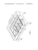
[0017]FIG. 1 is a perspective view of a gas stove in which an ignition device in accordance with the present invention is mounted;
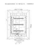
[0018]FIG. 2 is a top view of the gas stove in FIG. 1;
[0019]FIG. 3 is a side view in partial section of the gas stove in FIG. 1;
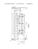
[0020]FIG. 4 is a front view in partial section of the gas stove in FIG. 1;
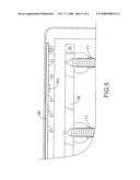
[0021]FIG. 5 is an enlarged front view in partial section of the gas stove in FIG. 1; and
[0022]FIG. 6 is a top view of a conventional gas stove in which a conventional ignition device in accordance with the prior art is mounted.
DETAILED DESCRIPTION OF THE PREFERRED EMBODIMENT
[0023]With reference to FIG. 1, a gas stove has a stove base (10), multiple elongated burners (11), an outlet tube (30) and an ignition device in accordance with the present invention.
[0024]The stove base (10) has a burner chamber. The burner chamber is formed in the stove base (10) and has an inner surface (not numbered) and at least one mounting lug (101). The at least one mounting lug (101) is formed on and protrudes from the inner surface of the burner chamber. The elongated burners (11) are mounted in the burner chamber in the stove base (10) at intervals, and each elongated burner (11) has two opposite narrow ends and a gas inlet (111). The elongated burners (11) mounted at intervals can provide adequate flames to consume gas economically.
[0025]With further reference to FIG. 3, the outlet tube (30) is mounted in the burner chamber and has an outer surface (not numbered) and multiple gas nozzles (31). The gas nozzles (31) are mounted in the outer surface of the outlet tube (30) and align respectively with the gas inlets (111) of the elongated burners (11). So, gas in the outlet tube (30) can be injected into and gushes out of the elongated burners (11) through the gas nozzles (31).
[0026]With further reference to FIG. 2, the ignition device in accordance with the present invention is mounted in the stove base (10) and comprises a gas valve assembly (70), an electronic igniter (16), a flame restrictor (15) and a triggering knob (14).
[0027]The gas valve assembly (70) is mounted in the stove base (10) adjacent to the elongated burners (11) and has a gas valve (7 1), an inlet tube (72) and an extending tube (20).
[0028]The gas valve (71) has a distal end (not numbered), an inlet (not numbered), an outlet (not numbered), a mounting hole (712) and a valve nozzle (711). The outlet of the gas valve (71) is connected to the outlet tube (30) to channel gas to the outlet tube (30). The valve nozzle (711) is formed on and protrudes from the distal end of the gas valve (71), extends toward the elongated burners (11) perpendicularly to the elongated burners (11) to form a discharge path and spray gas toward the elongated burners (11).
[0029]The inlet tube (72) is connected to the inlet of the gas valve (71) to connect the gas valve (71) to an external gas source to provide gas to the gas stove when the gas valve (71) is opened.
[0030]The extending tube (20) is mounted on the inner surface of the burner chamber in the stove base (10), is connected to the mounting hole (712) of the gas valve (71), communicates with and receives gas from the gas valve (71) and extends perpendicularly to the elongated burners (11) adjacent to one of the narrow ends of the elongated burners (11). The extending tube (20) may be mounted on the at least one mounting lug (101). The extending tube (20) has a rear section (not numbered) and multiple gas holes (21). With further reference to FIG. 5, the gas holes (21) are formed through the extending tube (20) at intervals shorter than that between adjacent elongated burners (11). Gas in the extending tube (20) can be ejected from the gas holes (21) toward the elongated burners (11). The gas holes (21) may be only formed within the rear section of the extending tube (20) to economically eject the gas.
[0031]The electronic igniter (16) is mounted near the valve nozzle (711) and has an electrode (161). The electrode (161) extends into the discharge path of the valve nozzle (711) and produces sparkles to ignite the gas ejected from the valve nozzle (711) to generate a starting flame tongue.
[0032]The flame restrictor (15) is mounted near the electrode (161) of the electronic igniter (16) partially around the discharge path of the valve nozzle (711) to keep the starting flame tongue from excessively expanding and directs the starting flame tongue toward the elongated burners (11) to ignite gas ejected from the elongated burners (11).
[0033]When the starting flame tongue extends, gas simultaneously ejected from the gas holes (21) in the extending tube (20) mixes with gas simultaneously ejected from the elongated burners (11). Because the interval between adjacent gas holes (21) is shorter than that between adjacent elongated burners (11), the mixed gas forms a continuous gas cloud over the elongated burners (11). Accordingly, even though the starting flame tongue cannot extend through all of the elongated burners (11), the gas cloud is ignited when the starting flame tongue touches the gas cloud, and all the elongated burners (11) are instantly ignited to prevent gas from leaking out of the elongated burners (11) and effectively reducing leakage of gas.
[0034]With further to FIG. 4, the gas cloud does not need to be formed over the front of the elongated burners (11) over which the starting flame tongue extends, because gas ejected from the elongated burners (11) can be ignited by the starting flame tongue. However, the gas cloud has to be formed over the rear of the elongated burners (11) over which the starting flame tongue cannot extend, so when the starting flame tongue is long enough to touch the gas cloud, the rear of the elongated burners (11) can be instantly ignited.
[0035]Therefore, when the starting flame tongue extends over the rear section of the extending tube (20), the gas holes (21) merely need to be formed within the rear section of the extending tube (20) and are away from an elongated burner closest to the gas valve (71) to form a gas cloud over the rear of the elongated burners (11) over which the starting flame tongue cannot extend, to economically eject the gas.
[0036]The triggering knob (14) is mounted on the stove base (10), is connected electrically to the electronic igniter (16) and is connected to and operates the gas valve (71) to selectively open and close the gas valve (71). When the triggering knob (14) is pressed and turned, the gas valve (71) is opened and the electrode (161) of the igniter (16) induces an electric discharge phenomenon to produce sparkles.
[0037]Even though numerous characteristics and advantages of the present invention have been set forth in the foregoing description, together with details of the structure and function of the invention, the disclosure is illustrative only, and changes may be made in detail, especially in matters of shape, size, and arrangement of parts within the principles of the invention to the full extent indicated by the broad general meaning of the terms in which the appended claims are expressed.
User Contributions:
comments("1"); ?> comment_form("1"); ?>Inventors list |
Agents list |
Assignees list |
List by place |
Classification tree browser |
Top 100 Inventors |
Top 100 Agents |
Top 100 Assignees |
Usenet FAQ Index |
Documents |
Other FAQs |
User Contributions:
Comment about this patent or add new information about this topic:
Images included with this patent application:
 |  |
 |  |
 |  |
 |
| Similar patent applications: | |
| Date | Title |
|---|---|
| 2014-04-03 | Process for producing an element for absorbing solar radiation for a thermal concentrating solar power plant |
| 2014-03-20 | Burner for a gas cooktop |
| 2011-03-10 | Hood device for grill |
| 2014-03-27 | Built-in retractable ventilation hood assembly |
| 2012-05-17 | Switch of a gas valve unit |
| New patent applications in this class: | |
| Date | Title |
|---|---|
| 2015-05-28 | Burner assembly for cooktop appliance and method for operating same |
| 2013-08-22 | Multi-gas appliance |
| 2013-03-21 | Method of mounting gas burner to sheet metal or glass cooktop |
| 2012-10-25 | Burner and cooker including the burner |
| 2012-05-31 | Burner illumination in an appliance |
| New patent applications from these inventors: | |
| Date | Title |
|---|---|
| 2015-01-22 | Retractable and adjustable heating brace |
| 2014-05-22 | Heating pad assembly |
| 2014-04-03 | Heating device for motorcycle suits |
| 2014-02-06 | Temperature control module for electric blankets |
| 2010-05-13 | Heating process that keeps a heating apparatus at a constant temperature by the power supply of a portable battery |
| Top Inventors for class "Stoves and furnaces" | |
| Rank | Inventor's name |
|---|---|
| 1 | Paul Bryan Cadima |
| 2 | David Deng |
| 3 | Andrew Plotkin |
| 4 | Peter Emery Von Behrens |
| 5 | Derek W. Schrock |