Patent application title: ACTUATING DEVICE FOR A DRAIN FITTING AND DRAIN FITTING WITH SUCH AN ACTUATING DEVICE AND METHOD OF MOUNTING SUCH A DRAIN FITTING
Inventors:
Alfred Mahler (Ruti, CH)
Assignees:
Geberit Technik AG
IPC8 Class: AE03D134FI
USPC Class:
4410
Class name: With outlet valve actuator button type
Publication date: 2008-11-27
Patent application number: 20080289091
Inventors list |
Agents list |
Assignees list |
List by place |
Classification tree browser |
Top 100 Inventors |
Top 100 Agents |
Top 100 Assignees |
Usenet FAQ Index |
Documents |
Other FAQs |
Patent application title: ACTUATING DEVICE FOR A DRAIN FITTING AND DRAIN FITTING WITH SUCH AN ACTUATING DEVICE AND METHOD OF MOUNTING SUCH A DRAIN FITTING
Inventors:
Alfred MAHLER
Agents:
SUGHRUE MION, PLLC
Assignees:
Geberit Technik AG
Origin: WASHINGTON, DC US
IPC8 Class: AE03D134FI
USPC Class:
4410
Abstract:
The actuating device comprises a push button housing (7), which may be
inserted into an opening (4) in the cistern lid (2). At least one push
button (8, 9) and a pusher (11) are mounted in the push button housing
(7) for triggering flushing. The push button housing (7) is fastened only
to the cistern lid (2) and may be lifted with the cistern lid (2) off the
at least one push button (8, 9) and the pusher (11). The actuating device
is particularly suitable for cisterns of ceramic material and enables
simpler and quicker mounting as well as servicing of the cistern.Claims:
1.-14. (canceled)
15. Actuating device for a drain fitting of a cistern, having a push button housing, which may be inserted into an opening in a cistern lid, having at least one push button mounted in this push button housing and having a pusher, which may be moved downwards to trigger flushing by actuation of the at least one push button, wherein the push button housing is fastened only to the cistern lid and may be lifted off the at least one push button and the pusher together with the cistern lid.
16. Device according to claim 15, wherein the at least one push button, the pusher, a guide element and the push button housing form a unit.
17. Device according to claim 16, wherein said unit may be screwed on.
18. Device according to claim 17, wherein the guide element comprises an external thread to fasten it to the drain valve.
19. Device according to claim 18, wherein the push button housing is connected for rotation to the guide element, such that the actuating device may be screwed onto the drain fitting using the push button housing as mounting aid.
20. Device according to claim 19, wherein the push button housing comprises at its bottom edge at least one recess, in which engages a dog of the guide element.
21. Device according to claim 15, wherein the push button housing comprises in a lower region an external thread for a fastening nut.
22. Device according to claim 15, wherein the pusher comprises a pin, which is screwed into a sleeve, the pin being connected to a push button and the sleeve being movable downwards to trigger flushing.
23. Drain fitting having an actuating device according to claim 15, wherein it comprises at least one lever for triggering flushing, which may be swivelled upon actuation by the actuating device.
24. Drain fitting according to claim 23, wherein it comprises a connecting element, which connects the drain valve to the actuating device.
25. Drain fitting according to claim 23, wherein it is provided for dual flushing and that the actuating device comprises two push buttons.
26. Method of mounting a drain fitting according to claim 23, wherein the cistern lid is set in place, the actuating device is fastened as a mounting unit to the drain valve through an opening in the cistern lid.
27. Method according to claim 26, wherein the mounting unit is screwed onto a yoke of the drain valve.
28. Method according to claim 26, wherein upon fastening of the mounting unit to the drain valve, a pin connected to a push button is screwed into a sleeve, the pin forming with the sleeve a pusher.
Description:
[0001]The invention relates to an actuating device for a drain fitting of
a flushing cistern, having a push button housing, which may be inserted
into an opening in a cistern lid, having at least one push button mounted
in this push button housing and having a pusher, which may be moved
downwards to trigger flushing by actuation of the at least one push
button.
[0002]Actuating devices of this type are known and are suitable in particular for ceramic cisterns, which display significant variations in size due to production conditions. These actuating devices have thus to be constructed in such a way that they may be adapted to different cistern dimensions and in particular to different cistern lid thicknesses. This adaptability requires comparatively great structural complexity and also special, likewise comparatively complex mounting. During servicing the actuating device has accordingly to be demounted and then remounted, which is likewise comparatively complex.
[0003]An actuating device of the stated type has become known in the prior art from WO 01/46528. This enables adaptation to different sizes of cistern, and additionally enables dual flushing. However, here too mounting of the actuating device is comparatively complex. This also applies to servicing.
[0004]The object of the invention is to provide an actuating device of the stated type which enables simpler mounting. The actuating device is intended nevertheless to be inexpensive to manufacture and functionally reliable.
[0005]The object is achieved in the case of an actuating device of the above type in that the push button housing is fastened only to the cistern lid and may be lifted off the at least one push button and the pusher with the cistern lid. In the case of the actuating device according to the invention, the push button housing is not connected fixedly to the at least one push button and the pusher in the mounted state, but rather may be lifted off them. This has the significant advantage that the cistern lid may be simply lifted and then set back in place during mounting and servicing. Mounting is accordingly also simplified, since the at least one push button and the pusher may be checked while the lid is lifted and the lid with the push button housing may be set in place at the end.
[0006]According to a further development of the invention, the push button housing, the push button and the pusher form a separate insert. According to a further development of the invention, this insert additionally comprises a guide element, in which the pusher is guided.
[0007]According to a further development of the invention, the insert comprises means for screw-fastening to a yoke of the drain fitting. Such a screw-fastening enables depth adjustment of the insert, so enabling particularly simple adaptation to different cistern sizes.
[0008]This is particularly simple when, according to a further development of the invention, the guide element may be screwed onto a connecting element. The connecting element in particular connects the guide element to said yoke.
[0009]According to a further development of the invention, the push button housing is connected for rotation to the guide element, such that the insert may be screwed onto the drain fitting using the push button housing as mounting aid. This has the significant advantage that the insert may be fastened in a precisely positioned manner to the drain valve when the cistern lid is in place. The push button housing serves in this case as a tool for screwing on the insert. The final position of the screwing process is here preferably the final position of the push button housing. The push button housing is thus screwed downwards with said insert when the cistern lid is in place, until for example a collar of the push button housing rests on the top of the cistern lid. The insert has then reached its correct position. The push button housing may then be lifted off with the cistern lid and fastened to the cistern lid for example by means of a nut. To screw on the nut, the push button housing preferably has an external thread in a lower region.
[0010]The insert is preferably constructed in such a way that dual flushing is possible. For example, its components comprise one push button for a full flush and a further push button for a partial flush. In principle, however, an actuating device with just one push button is also feasible.
[0011]The invention further relates to a drain fitting with an actuating device according to the invention. In this drain fitting, the actuating device is arranged on a yoke of a drain valve of the drain fitting. According to a further development of the invention, the actuating device is connected to this yoke by a connecting element. Preferably, this connecting element has an external thread, onto which a guide element of the actuating device is screwed.
[0012]The invention further relates to a method of mounting such a drain fitting.
[0013]Further advantageous features are revealed by the dependent patent claims, the description which follows and the drawings.
[0014]An exemplary embodiment of the invention is explained in greater detail below with reference to the drawings, in which:
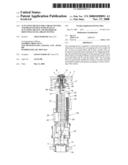
[0015]FIG. 1 is a partially sectional view of a drain fitting according to the present invention, showing portions of the lid and of the tank of the cistern,
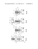
[0016]FIG. 2 is a view of the actuating device according to the invention,
[0017]FIG. 3 is a plan view of the actuating device according to FIG. 2,
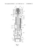
[0018]FIG. 4 shows a section through the actuating device along line IV-IV of FIG. 3,
[0019]FIG. 5 is a three-dimensional view of the actuating device according to the invention and
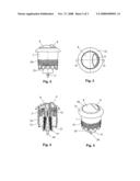
[0020]FIGS. 6a-6d show individual steps during mounting of the actuating device according to the invention.
[0021]FIG. 1 shows a drain fitting 32, which is mounted in a flushing cistern 1 and which consists of an actuating device 6 and a float valve 20. The float valve 20 is inserted into an opening 5 in a cistern tank 3 and fastened by a fastening nut 33 to the bottom of the cistern tank 3. The float valve 20 comprises a housing 31, in which an overflow pipe 21 or another suitable closing member is mounted so as to be liftable. The float valve 20 is designed for dual flushing and has to this end an upper float 22 and a lower float 23. To lift the overflow pipe 21 and thus trigger flushing, a pull rod 34 is provided, which acts at a lower end on the overflow pipe 21 and which cooperates via an articulated linkage 35 with the actuating device 6. The linkage 35 is connected by pivots 17 to a yoke 14, which is connected via two downwardly projecting webs 14a to the housing 31. The float valve 20 may also be replaced by another suitable drain valve. In particular, the float valve 20 does not absolutely have to take the form of a dual valve.
[0022]The actuating device 6 is mounted in an opening 4 (FIG. 6a) in the cistern lid 2. This opening 4 is preferably a circular opening. The cistern lid 2 here consists for example of ceramic material. As is conventional, it is positioned removably on an upper edge, not shown here, of the cistern tank 3. The actuating device 6 has a preferably cylindrical push button housing 7 with an upper, outwardly projecting collar 7a, which in the mounted state rests on the top 36 (FIG. 6b) of the cistern lid 2. According to FIG. 6c, the push button housing 7 has a cylindrical inside 30 and a plurality of recesses 25 at a lower, crown-shaped edge. It is fastened to the cistern lid 2 by a nut 13, which is screwed onto a thread 24 of the push button housing 7.
[0023]In the push button housing 7 there are mounted two push buttons 8 and 9, which may be moved downwards by hand to trigger flushing. If only push button 8 is pressed, a full flush is triggered, during which substantially all the water present in the cistern 1 is used for flushing. If the large push button 8 is pressed with the small push button 9, only a partial flush is triggered. In addition, a guide element 12 is mounted in the push button housing 7 and, in accordance with FIG. 6a, comprises an internal thread 27, which is screwed onto an external thread 28 of a connecting element 15. The screw-in depth of the guide element 17 is adjustable relative to the connecting element 15. A spring 10 is supported on the guide element 12, which spring is tensioned against the push buttons 8 and 9. A pusher 11 is arranged inside the connecting element 15, which pusher 11 may be moved downwards by the push buttons 8 and 9 in order to swivel a two-armed lever 16 of the linkage 35. The pusher 11 consists of a pin 40, which comprises a thread 41 on the outside (FIG. 4) and which is screwed into a sleeve 37, which according to FIG. 6a has a corresponding thread 42. The pin 40 is connected at the top end to the push button 8 and is moved downwards thereby to trigger flushing.
[0024]The sleeve 37 extends substantially over the entire length of the connecting element 15, as shown for example in FIG. 1. If the lever 16 is swivelled about the pivot 17, a connecting rod 18 connected to the lever 16 is lifted via a pivot 19. This connecting rod 18 is connected to the pull rod 34, which thus lifts the overflow pipe 21 in a manner known per se and thus triggers flushing. When push buttons 8 and 9 are released, the spring 10 moves the push buttons 8 and 9 back into the starting position shown in FIG. 1. In the case of a full flush, this applies accordingly only to the push button 8. The small push button 9 mounted in the push button 8 then remains in the starting position.
[0025]The guide element 12 is connected to the yoke 14 via the connecting element 15. It is thus stationary during actuation. According to FIG. 1, the connecting element 15 is inserted non-rotatably with its bottom end into an opening 38 in a web 39 of the yoke 14. The guide element 12 may thus be screwed onto the connecting element 15, without the latter turning. As already mentioned, different screw-in depths are possible for the guide element 12. FIG. 1 shows a middle screw-in depth. The guide element 12 may thus also be screwed further down or up. This is dependent on the thickness and position of the cistern lid 2.
[0026]As is apparent, the guide element 12 is arranged within the push button housing 7 but is not firmly connected thereto. This likewise applies to the two push buttons 8 and 9. The cistern lid 2 may therefore be lifted off the drain fitting 32 together with the push button housing 7 and the nut 13. When the cistern lid 2 is lifted, the push buttons 8 and 9, the pusher 11 and the sleeve 37 then thus remain mounted fixedly on the connecting element 15 or the yoke 14. The two push buttons 8 and 9 work even when the lid 2 has been lifted off. Flushing may thus be triggered even when the lid 2 has been lifted off and thus without push button housing 7.
[0027]The push button housing 7, the push buttons 8 and 9, the spring 10, the guide element 12 and the pusher 11 form a mounting unit 29, which is prefabricated and which may be connected detachably as a unit to the float valve 20.
[0028]The above-mentioned functional separation between the push button housing 7 and the parts arranged therein enables simple and quick mounting, which will be explained in greater detail below with reference to FIGS. 6a to 6d.
[0029]FIG. 6a shows the cistern 1 with mounted float valve 20 and lid 2 in place thereon. As mentioned above, the push button housing 7 forms a mounting unit 29 with the push buttons 8 and 9, the guide element 12 and the pusher 11 together with the spring 10. This mounting unit 29 is likewise illustrated in FIGS. 2 and 5. As shown in particular in FIG. 5, the guide element 12 has at least one cam-type dog 26, which engages in one of the recesses 25. In principle, a plurality of such dogs 26 may also be provided. These then each engage from below in a recess 25.
[0030]The mounting unit 29 is inserted from above into the opening 4 and screwed onto the thread 28 of the connecting element 15 by turning the push button housing 7, until the collar 7a rests on the top 36 of the cistern lid 2 as shown in FIG. 6b. Due to the engagement of the dog 26 with the push button housing 7, the guide element 12 is accordingly also turned when the push button housing 7 is turned. Simultaneously with the guide element 12, the pin 40 is also turned and screwed into the sleeve 37. Turning of the mounting unit 29 by means of the push button housing 7 thus simultaneously connects the guide element 12 to the yoke 14 and the pin 40 to the sleeve 37. Both connections are depth-adjustable for the purpose of adaptation to the cistern lid 2.
[0031]Once the mounting unit 29 has been fastened to the yoke 14 in accordance with FIG. 6b, the lid 2 is lifted off the cistern tank 3 with the push button housing 7, as shown in FIG. 6c. The nut 13 is then screwed onto the push button housing 7 from the underside of the lid 2 and thus the push button housing 7 is firmly connected to the cistern lid 2. The cistern lid 2 may then be set back in place with the push button housing 7. The drain fitting 32 is thus mounted in accordance with FIG. 6d.
[0032]If the cistern 1 is serviced, the cistern lid 2 may be straightforwardly lifted off the cistern tank 3. The push button housing 7 then remains on the cistern lid 2. The drain fitting is fully functional even when the cistern lid 2 has been lifted off. The flushing function may thus be checked while the cistern lid 2 is off. After servicing, the cistern lid 2 may be set back in place, after which the cistern 1 is again functional.
TABLE-US-00001 List of reference numerals 1 Cistern 2 Cistern lid 3 Cistern tank 4 Opening 5 Opening 6 Actuating device 7 Push button housing 7a Collar 8 Push button 9 Push button 10 Spring 11 Pusher 12 Guide element 13 Nut 14 Yoke 14a Web 15 Connecting element 16 Lever 17 Pivot 18 Connecting rod 19 Pivot 20 Float valve 21 Overflow pipe 22 Upper float 23 Lower float 24 Thread 25 Recess 26 Dog 27 Thread 28 Thread 29 Mounting unit 30 Inside 31 Housing 32 Drain fitting 33 Fastening means 34 Pull rod 35 Linkage 36 Top 37 Sleeve 38 Opening 39 Web 40 Pin 41 Thread 42 Thread 43 Collar
User Contributions:
comments("1"); ?> comment_form("1"); ?>Inventors list |
Agents list |
Assignees list |
List by place |
Classification tree browser |
Top 100 Inventors |
Top 100 Agents |
Top 100 Assignees |
Usenet FAQ Index |
Documents |
Other FAQs |
User Contributions:
Comment about this patent or add new information about this topic:
Images included with this patent application:
 |  |
 |  |
| Similar patent applications: | |
| Date | Title |
|---|---|
| 2012-08-23 | Hand drying device and washing stand for an aircraft |
| 2012-10-04 | Shower caddy retaining apparatus and methods thereof |
| 2011-12-01 | Devices for use in the treatment of fluids |
| 2012-06-21 | Overmolded fitting connection with color indication |
| 2012-09-20 | Excrement automatic cleaning apparatus without taking it off |
| New patent applications in this class: | |
| Date | Title |
|---|---|
| 2014-06-19 | Actuating device for a drain fitting |
| 2014-03-13 | Motorized automate/manual push button system |
| 2008-08-28 | Toilet bowl flushing water tank device |
| New patent applications from these inventors: | |
| Date | Title |
|---|---|
| 2015-04-30 | Drainage fitting for a cistern |
| 2008-12-25 | Discharge valve for a flushing cistern |
| Top Inventors for class "Baths, closets, sinks, and spittoons" | |
| Rank | Inventor's name |
|---|---|
| 1 | William T. Ball |
| 2 | Joseph R. Cook |
| 3 | David Grover |
| 4 | Kun Yuan Tong |
| 5 | Victor Hoernig |