Patent application title: Shower trap heat recovery apparatus
Inventors:
Thomas Christopher Cournane (Richford, VT, US)
IPC8 Class: AF28D700FI
USPC Class:
165164
Class name: Heat exchange flow passages for two confined fluids
Publication date: 2008-10-23
Patent application number: 20080257535
Inventors list |
Agents list |
Assignees list |
List by place |
Classification tree browser |
Top 100 Inventors |
Top 100 Agents |
Top 100 Assignees |
Usenet FAQ Index |
Documents |
Other FAQs |
Patent application title: Shower trap heat recovery apparatus
Inventors:
Thomas Christopher Cournane
Agents:
Thomas C. Cournane
Assignees:
Origin: RICHFORD, VT US
IPC8 Class: AF28D700FI
USPC Class:
165164
Abstract:
A plurality of isolated heat pipe cells (21) are in serial thermal
communication with counter-flowing drain gray water discharge channel
(31) and cold water supply channel (11) in a compact plastic-molded
assembly.Claims:
1. Apparatus for recovering waste heat from gray water discharge
comprising:(a) a plurality of thermally isolated heat pipes(b) a first
channel accommodating flow of said gray water, and(c) a second channel
accommodating flow of a cold water supplywherein each of said heat pipes
is in thermal communication with said first and second channels, which
channels being elongated with adjacent conforming common extent.
2. Apparatus as defined in claim 1 wherein:(a) said heat pipes are serially disposed at intervals along the common extent of said first and said second channels, and(b) direction of flow of said gray water is counter to direction of flow of said cold waterwhereby said heat pipes provide a means for sequential transfer of incremental quantities of heat from said gray water to said cold water.
3. Apparatus as defined in claim 1 wherein:(a) said heat pipes are disposed at predetermined intervals along a common extent of said first and said second channels, and(b) heat transfer capacity of said heat pipes is individually predeterminedwhereby aggregate heat transfer is optimized.
4. Apparatus as defined in claim 1 constructed largely of a moldable material with heat conducting means for thermal communication between said heat pipes and said first and said second channels.
5. Apparatus as defined in claim 1 wherein the body of said apparatus is constructed largely of a moldable material within which body said heat pipes are embedded, which heat pipes being constructed of a heat-conducting material.
6. Apparatus as defined in claim 1 wherein said heat pipes are charged with a working fluid.
7. Apparatus as defined in claim 1 wherein said heat pipes are charged with water as a working fluid.
8. Apparatus as defined in claim 1 wherein said gray water flow channel has a plurality of baffle means whereby, under gravity flow, said gray water channel is maintained substantially filled.
9. Apparatus as defined in claim 1 wherein said gray water flow channel has at least one baffle, whereby said baffle inhibits flow of drain vapors.
10. Apparatus for recovering waste heat from gray water discharge comprising:(a) an elongated first channel accommodating flow of said gray water(b) an elongated second channel accommodating flow of a cold water supply, which second channel shares a common conforming extent with said first channel(c) a plurality of thermally isolated heat pipes, each in thermal communication with said first and second channels, which heat pipes being serially disposed at intervals along said common extent of said channelswhereby, said gray water flow direction being counter to said cold water flow direction, said heat pipes provide a means for sequential transfer of incremental quantities of heat from said gray water to said cold water.
11. Apparatus as defined in claim 10 constructed largely of a moldable material with heat conducting means for thermal communication between said heat pipes and said first and said second channels.
12. Apparatus as defined in claim 10 wherein the body of said apparatus is constructed largely of a moldable material within which body said heat pipes are embedded, which heat pipes being constructed of a heat-conducting material.
13. Apparatus as defined in claim 10 wherein said heat pipes are charged with a working fluid.
14. Apparatus as defined in claim 10 wherein said heat pipes are charged with water as a working fluid.
15. Apparatus as defined in claim 10 wherein said gray water flow channel has a plurality of baffle means whereby under gravity flow said gray water channel is maintained substantially filled.
16. Apparatus as defined in claim 10 wherein said gray water flow channel has at least one baffle, whereby said baffle inhibits flow of drain vapors.
17. Apparatus as defined in claim 10 wherein:(a) said heat pipes are disposed at predetermined intervals along a common extent of said first and said second channels, and(b) heat transfer capacity of said heat pipes is individually predeterminedwhereby aggregate heat transfer is optimized.
18. Apparatus for exchanging heat between two fluid flowstreams comprising:(a) plurality of thermally isolated heat pipes(b) a first channel accommodating flow of a first fluid(c) a second channel accommodating flow of a second fluidwherein each of said heat pipes is in thermal communication with said first and said second channels, which channels are elongated with adjacent conforming common extent.
19. Apparatus as defined in claim 18 wherein:(a) said heat pipes are serially disposed at intervals along the common extent of said first and said second channels, and(c) direction of flow of said first fluid is counter to direction of flow of said second fluid.whereby said heat pipes provide a means for sequential exchange of incremental quantities of heat between said first fluid and said second fluid.
20. Apparatus as defined in claim 18 wherein the body of said apparatus is constructed largely of a moldable material within which body said heat pipes are embedded, which heat pipes being constructed of a heat-conducting material.
Description:
CROSS-REFERENCE TO RELATED APPLICATIONS
[0001]This applicant claims the benefit of Provisional Patent Application No. 60/925,635, filed Apr. 23, 2007 by the present inventor.
FEDERALLY SPONSORED RESEARCH
[0002]Not Applicable
SEQUENCE LISTING OR PROGRAM
[0003]Not applicable
BACKGROUND
[0004]1. Field of Invention
[0005]The invention relates to a novel method and apparatus to recover heat energy from domestic gray water discharge. More specifically, the invention relates to such a method and apparatus utilizing a compact, molded, multi-cell heat pipe exchanger core, particularly suited to heat recovery from shower gray water.
[0006]["Gray Water" is drain discharge that may contain contaminants such as soap or chemicals.]
[0007]2. Prior Art
[0008]Methods and apparatuses for recovering heat energy from domestic gray water discharge are known in the art. In one such method a section of the plumbing drain piping, which is typically plastic, is replaced with an equivalent section of copper pipe around the outside of which is coiled multiple turns of spirally wound smaller copper tubing with each turn in direct contact with the drain pipe, which tubing carries cold water, usually the intake supply to the water heater tank. Heat conducted from the gray water through the walls of the copper pipe and tubing preheats the cold water. With this method heat recovery is based on the conduction of sensible heat from the gray water to the cold water, driven by the positive temperature differential between the two. Since this temperature differential is relatively small the resultant heat flux density is low requiring an elongated apparatus to provide adequate contact area and dwell time. To recover significant heat from gray water this apparatus is large, typically four feet or so in length, is cumbersome to install, and is expensive given the large copper content required.
[0009]In a variation of a copper conductive sensible heat recovery apparatus U.S. Pat. No. 4,619,311 describes a method whereby gray water discharge is induced to flow by gravity in a film down the inside of a vertically disposed section of copper pipe installed in the drain line, around the outside of which multiple turns of smaller copper tubing are spirally wound in a similar manner to the first described method, by which means sensible heat is conducted from the gray water to cold water flowing in the smaller tubing. This method increases heat transfer efficiency but also requires a similarly large and expensive copper apparatus.
[0010]Other methods of recovering heat from domestic gray water are described in U.S. Pat. Nos. 4,304,292 4,300,247 4,321,798 4,352,391 and 4,372,372. The methods described employ conduction of sensible heat through various forms and applications of conductive heat exchangers and as such entail large, cumbersome, and expensive copper or other conductive metal construction. Such conductive heat exchangers, usually copper, are expensive to build and install and have had limited market success.
[0011]A different method and apparatus, with variations, for waste heat recovery is described in related US Patent Applications 2006/0231235, 2007/0187071, 2007/0284087, 2007/0289721, and 2008/0011458. These patent applications describe a method for the transfer of heat from the exhaust gas of an internal combustion engine to the engine liquid coolant by means of evaporating a liquid fluid contained in a multi-compartment thermally conductive container disposed in the path of the exhaust gas, and condensing the vapors in a conductive container disposed in the coolant circuit with closed loop means for returning the condensate. Devices for the transfer of heat by means of the phase change of a fluid are known in the art and are broadly referred to as heat pipes. The purpose of the apparatuses described in the applications is to reduce the time required to bring the engine and cabin heater of an automobile up to normal operating temperature. As such the methods and apparatuses described are suitable for the high temperature and high heat content of engine exhaust gas and the high temperature differential between the exhaust gas and the coolant water wherein only a small portion of the exhaust heat is transferred to the coolant with subsequent negligible reduction of the temperature differential. Controllable fluid flow-limiting mechanical valves are required to prevent overheating and overpressure in the fluid vapors. These methods, applied to gray water heat recovery, would be ineffective as the simultaneous heating of the evaporator compartments (all, effectively, at the one temperature) and likewise the simultaneous cooling of the condenser compartments would, given the equal or somewhat equal gray and cold water mass flowrates, result in the falling temperature of the gray water and the rising temperature of the cold water approaching some median value, at which point no further heat transfer would take place, greatly reducing heat transfer.
[0012]Canada Patent 2217972 describes a gray water heat recovery device employing a loop type heat pipe to exchange heat by means of a refrigerant fluid circulating between an annular evaporator compartment concentrically surrounding a section of the drain stack and a condenser compartment surrounding a cold water-preheating tank with communicating vapor and liquid piping for circulation of the working fluid. A wick is provided surrounding the drain stack to bring the refrigerant into thermal contact with the gray water. This method provides improved efficiency but is complex and expensive requiring an elongated copper or similar heat exchanger in the drain stack and a special heat-exchanging water storage tank.
[0013]Such methods employing heat pipes have not been successfully or economically applied to gray water heat recovery.
SUMMARY
[0014]It is an object of the invention to provide a method and apparatus for recovery of heat energy from heated gray water discharge that overcomes the size, cost, and ease-of-installation limitations of prior art.
[0015]A more specific object of the invention is to provide such a method and apparatus that comprises a compact molded device employing a multi-cell heat pipe core for high efficiency heat transfer from heated gray water discharge to intake cold water.
[0016]Another object of the invention is to provide a method and apparatus that significantly reduces the hot water, and thereby energy, consumption of domestic showers.
First Embodiment
[0017]In accordance with a particular embodiment of the invention an apparatus is provided for recovery of waste heat from domestic gray water comprising:
[0018]a molded assembly consisting of an upper cold water section, a lower drain water section and a central core section with a plurality of cell cavities, which conforming sections, fixed and sealed together with thermally conductive thin plate metal gaskets sandwiched one between the upper section and the core section and one between the core section and the lower section, form isolated flow channels for the drain and cold water, both of which channels being in thermal communication, over their common extent, with the central core cells via the gaskets, said gaskets hermetically sealing each cell of the core section;
[0019]said upper plastic molded section being shaped to provide an enlarged and elongated serpentine channel such that the cold water, under normal domestic water pressure, passes serially with reduced flow velocity and maximized contact over each cell of the core section;
[0020]said lower plastic molded section being shaped to provide a channel for the drain water such that the water is constrained to flow serially past the core section cells with internal baffles to ensure that the well under each cell is optimally filled under gravity flow, such baffles also serving the plumbing drain trap function;
[0021]said central core section, molded from plastic, aluminum, or other suitable material, comprising a plurality of individual cavity cells, isolated one from the other and distributed at intervals over the whole extent of the drain and cold water channels, each cell being charged with a predetermined amount of a suitable working fluid such as water, such amount in liquid phase being considerably less than the volume of the cell;
[0022]a vacuum being drawn and hermetically sealed in each cell of said center core at such pressure that the working fluid boils over the full temperature range of the drain water;
[0023]said assembly being installed such that, in equilibrium, the working fluid liquid rests substantially evenly in the bottom of each cell, the drain water and cold water being arranged to flow in counter direction to one another with the cold water in the upper channel;
[0024]said assembly forming a heat recovery apparatus fully contained in a unitary assembly installed in the gray water drain line replacing the traditional shower plumbing trap and connected in-line with the nearby cold water supply line to the shower control valve;
[0025]whereby, in operation, heat absorbed from the drain water via the lower conductive gasket causing the working fluid in each cell to boil, the resultant vapor rising to the top of each cell and condensing on thermal contact with the cold water via the upper conductive gasket, such condensate returning by gravity to the lower end of each cell, thereby setting up a rapid cyclic process of evaporation and condensation of the working fluid by which means the continuous exchange of the high latent heat of phase change of the fluid results in a high flux density heat transfer from the drain water to the cold water, such transfer being virtually lossless and being operable over the full temperature range of the drain water and with just a few degrees of temperature differential between the drain and cold waters,
[0026]whereby also the plurality of serially distributed isolated heat pipe cells in thermal communication with the counter-flowing drain and cold water enables each cell to "float" (temperature-wise) independently of all other cells, and transfer heat between the sequentially falling temperature profile of the drain water and the sequentially rising temperature profile of the cold water such that the cold water exiting the apparatus is heated to within a few degrees of the temperature of the drain water entering the apparatus, thereby providing a highly efficient means of heat recovery, preheating the cold water feed to the shower, which preheating reduces hot water and energy consumption while maintaining the requisite showerhead aggregate water temperature and flowrate.
Second Embodiment
[0027]In accordance with another particular embodiment of the invention an apparatus is provided for recovering waste heat from domestic gray water comprising:
[0028]a molded assembly consisting of an upper cold water section, a lower drain water section and a central core section with a plurality of isolated sealed conductive metal cylinders embedded vertically in the core such that they protrude upwards into the cold water channel and downwards into the drain water channel, which conforming sections, assembled, fixed and sealed together, form isolated flow channels for the drain and cold water, both of which channels being in thermal communication over their common extent with the central core metal cylinders;
[0029]said upper and lower plastic molded sections being respectively identical to those of the first described embodiment;
[0030]said plastic molded center core section containing a plurality of embedded metal, ideally copper, cylinders isolated one from the other and distributed at intervals over the whole common extent of the drain and cold water channels, each cylinder being charged with a predetermined amount of a suitable working fluid, such as water, such amount in liquid phase being considerably less than the volume of the cylinder;
[0031]a vacuum being drawn and hermetically sealed in each cylinder of said center core, thereby forming heat pipes, at such pressure that the working fluid boils over the full temperature range of the drain water;
[0032]said assembly being installed such that, in equilibrium, the working fluid rests substantially evenly in the bottom of each cylinder, the drain water and cold water being arranged to flow in counter direction to one another with the cold water in the upper channel;
[0033]whereby, in operation, heat is transferred from the drain water to the cold water in the same manner and to the same extent and effect as in the first described embodiment.
Operation of the Embodiments
[0034]Both described embodiments function, essentially, in the same manner, employing a plurality of serially distributed isolated heat pipes, thereby enabling efficient heat transfer from the drain water to the counter flowing intake cold water as previously outlined in the foregoing description of the embodiments. For typical drain gray water and cold-water temperatures and shower flowrates the recoverable heat load in the gray water discharge is about 12 kilowatts. The heat energy transfer capacity of heat pipes, with water as the working fluid and gravity condensate return, is known to be at least 250 watts per square centimeter (1.6 kilowatts/square inch) of heat pipe cross-sectional area when operating at the temperatures encountered in gray water. This characteristic of heat pipes provides heat transfer flux densities several orders of magnitude higher than that of conductive sensible heat exchangers. It is also known that the shorter the axial length the more efficiently a heat pipe performs. From the foregoing it is seen that a 12 kilowatt heat load requires a total aggregate heat pipe cross-sectional area of less than 50 square centimeters (8 square inches) thereby providing for efficient recovery of shower drain water heat load, or similar, to be accommodated in a physically small package, much smaller than required for a sensible copper heat exchanger with comparable heat transfer capacity. From this it will be understood that the assemblies described in the embodiments are compact such that they can be installed in the usual floor cavity space underneath a shower, or similar, where the plumbing trap would normally be placed thereby avoiding the necessity for remote placement and the attendant heat losses and plumbing costs. Also it is especially seen that the plurality of isolated heat pipes, distributed over the extent of the drain and cold water channels provides a means for virtually lossless transfer of the total recoverable heat from the drain gray water to the cold water, an efficiency not attainable with a practically sized sensible heat exchanger. Further it is seen that much of the apparatus can be constructed of inexpensive molded plumbing plastic such as PVC with minimal copper or other metal content, significantly reducing material and manufacturing costs.
DRAWINGS
[0035]This invention will be better understood by an examination of the following description together with the accompanying drawings, in which:
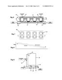
[0036]FIG. 1 is a cross-sectional view of the first described embodiment of the invention;
[0037]FIG. 2 illustrates in plan view the cold-water section of the first and second described embodiments.
[0038]FIG. 3 illustrates in plan view the heat pipe core section of the first described embodiment.
[0039]FIG. 4 illustrates in plan view the drain water section of the first and second described embodiments.
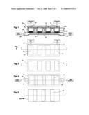
[0040]FIG. 5 illustrates the identical upper and lower metal plate gaskets of the first described embodiment.
[0041]FIG. 6 is a cross-sectional view of the second described embodiment of the invention.
[0042]FIG. 7 illustrates in plan view the heat pipe core of the second described embodiment.
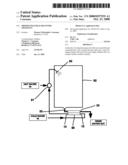
[0043]FIG. 8 graphically illustrates the temperature profiles of the drain and cold-water flow.
[0044]FIG. 9 illustrates application of the apparatus in shower gray water heat recovery.
[0045]Like reference numerals in the drawings indicate like elements.
DESCRIPTION OF PREFERRED EMBODIMENTS
First Embodiment
[0046]Referring to FIG. 1, in an embodiment of the invention an assembly consisting of three conforming molded sections, upper section 10, central core section 20, and lower section 30 is fixed and sealed together by means of a plurality of perimeter through-bolts (not shown) with closure sealing gaskets 40a and 40b, thereby forming flow channel 11 for the cold water with inlet 12 and outlet 13, flow channel 31 for the drain water with inlet 32, outlet 33 and a plurality of baffles 34, and a plurality of hermetically sealed and isolated cavity cells 21 in core 20. Cells 21 are in thermal communication with cold and drain water channels 11 and 31 respectively via conductive metallic gaskets 40a and 40b. A vacuum is drawn and individually sealed in cells 21, each of which is charged with a predetermined amount (substantially less than the cell cavity volume) of working fluid 22, such as water, thereby forming heat pipes wherein the vacuum pressure is such that the fluid boils over the full temperature range of the drain water.
[0047]Referring to FIG. 2, a serpentine cold water channel 11 is shown in the upper plastic molded section 10 the volume of which channel is expanded over cells 21 for reduced flow velocity and maximized contact thereby promoting heat transfer.
[0048]Referring to FIG. 3 a plurality of cavities is seen in central core section 20 which cavities, being sealed by gaskets 40a and 40b, form heat pipe cells 21. Core 20 is molded from plastic, aluminum, or other suitable material, and, as seen in FIG. 1, its undersurface is shaped to allow drain water to pass under gravity flow over baffles 34.
[0049]Referring to FIG. 4, drain water section 30 with inlet 32, outlet 33 and baffles 34 is seen. Baffles 34 conform to the shaped undersurface of section 20 and are located such that the well under each cell 21 is filled with drain water.
[0050]Identical flat copper (or other suitable conductive material) plate gaskets 40a and 40b depicted in FIG. 5 have a plurality of cutouts 41 to minimize lateral heat conduction between cells and, in the case of 40b, to allow passage of the drain water over baffles 34.
[0051]The number of heat pipe cells depicted is for illustration only.
Second Embodiment
[0052]Referring to FIG. 6, in a second embodiment of the invention, an assembly consisting of three conforming plastic molded sections, upper section 10, central core section 50, and lower section 30 is fixed and sealed together by means of a plurality of perimeter through-bolts (not shown) thereby forming cold water flow channel 11 with inlet 12 and outlet 13 and drain water flow channel 31 with inlet 32 and outlet 33. A plurality of thermally isolated hermetically sealed copper, or another conductive material, cylinders 51 are imbedded vertically in core 50 such that each cylinder protrudes into cold water flow channel 11 at its upper end and into the drain water flow channel 31 at its lower end. A vacuum is drawn in cylinders 51, each of which is charged with a predetermined amount (substantially less than the cylinder volume) of a suitable working fluid 52, such as water, thereby forming heat pipes. The equilibrium vacuum pressure is such that the working fluid boils over the full temperature range of the drain water.
[0053]Cold-water section 10 and drain water section 30 are constructed as previously described in the first embodiment with reference to FIG. 3 and FIG. 5 respectively.
[0054]Referring to FIG. 7, central core section 50 contains a plurality of isolated sealed cylinders forming heat pipes 51, which cylinders are embedded and sealed into this molded plastic core section, the heat pipes being distributed sequentially in pairs relative to the drain water channel 31, which arrangement is chosen to accommodate plumbing code requirements for shower drain dimensions.
[0055]The number of heat pipe cells depicted is for illustration only.
Application
[0056]Referring to FIG. 9 a typical application of the invention, in shower drain gray water heat recovery, is shown. An embodiment of the apparatus 50 is seen installed in place of a traditional drain trap immediately underneath shower compartment 52 with drain water inlet 32 and drain water outlet 33 connected to the shower drain as shown. Cold-water inlet 12 is connected to the cold water supply line and cold-water outlet 13 is connected to shower mixing valve 51. With this arrangement heat recovered from the drain gray water preheats the cold water supply to shower valve 51 thereby reducing the hot water supply line flow rate and hot water consumption while maintaining the requisite aggregate temperature and flowrate at showerhead 53.
[0057]As is usual practice the apparatus is plumbed into the drain line such that backflow or siphoning does not occur. Where the apparatus is specified to be installed below the gravity flowline of the drain, or the trap function is not required to ensure that drain channel 31 is filled, baffles 34 may be omitted from the embodiments.
Operation
[0058]In operation the embodiments depicted in FIG. 1 through FIG. 7 inclusive perform the same function. Cells 21 and 51 operating on the well-known heat pipe principle provide a mechanism for recovery of waste heat from gray water in a compact, low cost, apparatus. Since heat transfer by means of heat pipe cells 21 and 51 is determined by the exchange of the high latent heat of phase change of the working fluid 22 and 52 respectively, transported by the rapid cyclic evaporation and condensation of the fluid, the described embodiments transfer heat in a much smaller assembly than that required for sensible heat exchangers of comparable capacity. The heat pipe working fluid 22 and 52 is confined to a small cavity 21 or cylinder 51 in which the condensate is returned internally thereby avoiding the need for external return means, with attendant heat loss, complexity, and cost, as is required with loop type heat pipes.
[0059]Flow of the cold water counter to the drain water flow, combined with the plurality of serially distributed, thermally isolated, heat pipe cells, provides for sequential transfer of incremental quantities energy from the drain water to the cold water. Thermal isolation allows the operating temperature conditions of each of cells 21 and 51 to freely adjust, independently of all other cells, to the sequentially changing temperature profiles of the drain and cold water flow streams whereby the temperature of the cold water at outlet 13 is raised to within a few degrees of the drain water temperature at inlet 32 as depicted graphically in FIG. 8.
[0060]Each of cells 21 and 51 is inherently self-regulating. In the event of abnormal thermal conditions, such as excessive drain water temperature, the maximum rated transfer capacity of a cell is not exceeded as the internal vapor pressure of the fluid rises thereby limiting further evaporation and avoiding excessive heat transfer. Mechanical valve regulation is not required.
[0061]The embodiments have no moving or consumable components and no external power is required. The self-contained unitary assembly is amenable to standard plumbing practice requiring no special on-site assembly or adjustment.
[0062]It is seen, in both described embodiments, that the components can be molded largely from low-cost plumbing plastic such as PVC with minimal copper or other metal content, providing for a low cost apparatus which, being compact and lightweight, is also inexpensive to handle and install. This contrasts with sensible heat recovery apparatuses which are not amenable to plastic construction and require a much greater content of an expensive metal invariably copper, for comparable performance.
[0063]While the described first and second embodiments of the invention are particularly suited to recovery of waste heat from shower gray water wherein the cold and drain waters flow simultaneously and the flowrates are substantially unbalanced, the cold-water flowrate being less than that of the drain water, it will be understood that the invention could be adapted to other heat recovery and heat exchange applications, including such applications where the flowrates are balanced or substantially balanced.
[0064]Although particular embodiments have been described, this was for the purpose of illustrating, but not limiting, the invention. Various modifications which will come readily to mind of one skilled in the art are within the scope of the invention as defined in the appended claims.
User Contributions:
comments("1"); ?> comment_form("1"); ?>Inventors list |
Agents list |
Assignees list |
List by place |
Classification tree browser |
Top 100 Inventors |
Top 100 Agents |
Top 100 Assignees |
Usenet FAQ Index |
Documents |
Other FAQs |
User Contributions:
Comment about this patent or add new information about this topic:
Images included with this patent application:
 |  |
 |
| New patent applications in this class: | |
| Date | Title |
|---|---|
| 2016-05-12 | Heat exchanger |
| 2016-04-21 | Method for producing a heat exchanger module having at least two fluid flow circuits |
| 2016-03-17 | Manifold for process variable transmitter with steam coupling |
| 2016-02-25 | High effectiveness low pressure drop heat exchanger |
| 2016-01-07 | Countercurrent heat exchanger/reactor |
| Top Inventors for class "Heat exchange" | |
| Rank | Inventor's name |
|---|---|
| 1 | Levi A. Campbell |
| 2 | Chun-Chi Chen |
| 3 | Tai-Her Yang |
| 4 | Robert E. Simons |
| 5 | Richard C. Chu |