Patent application title: Supporting rack for screen
Inventors:
Hsiu Wu (Taipei Hsien, TW)
IPC8 Class: AA47F510FI
USPC Class:
211118
Class name: Specially mounted suspended type knockdown or foldable
Publication date: 2008-09-18
Patent application number: 20080223802
Inventors list |
Agents list |
Assignees list |
List by place |
Classification tree browser |
Top 100 Inventors |
Top 100 Agents |
Top 100 Assignees |
Usenet FAQ Index |
Documents |
Other FAQs |
Patent application title: Supporting rack for screen
Inventors:
Hsiu Wu
Agents:
BACON & THOMAS, PLLC
Assignees:
Origin: ALEXANDRIA, VA US
IPC8 Class: AA47F510FI
USPC Class:
211118
Abstract:
A supporting rack for supporting a thin screen at least comprising a base,
a supporting rod set and a screen positioning set, the supporting rod set
is provided at a position higher than the top of the screen positioning
set with a connecting member, a supporting arm and two supporting seats
to support and fix a plate for placing articles, the plate for placing
articles thus can form a platform, thereby the supporting rack can be
used for placing peripheral devices or other articles for documentary
works in addition to supporting the screen; and the space above the
screen can be effectively used.Claims:
1. A supporting rack for a screen, being provided on a base thereof with a
supporting rod set, said supporting rod set is provided at a level in its
middle section with a screen positioning set fixed on a back of said
screen, said supporting rack is characterized by that:said supporting rod
set is provided at a position higher than a top of said screen
positioning set further with a connecting member; said connecting member
is provided on its top with a fixing seat, and is provided on its two
lateral sides each with a transverse connecting port for extending
therethrough of a supporting arm; said supporting arm is provided on its
two ends each with a supporting seat bending to form an "L" shape; and
said fixing seat is on a same level as that of top surfaces of said
supporting seats in order that a plate for placing articles is fixed.
2. The supporting rack for a screen as claimed in claim 1, wherein said supporting rod set is provided further with an upper supporting rod and a hollow lower supporting rod slipped over said upper supporting rod, said connecting member is mounted on a top end of said upper supporting rod.
3. The supporting rack for a screen as claimed in claim 1, wherein said connecting member and said supporting rod set are matched and slipping connected with each other.
4. The supporting rack for a screen as claimed in claim 1, wherein said base is a counter balance weight.
5. The supporting rack for a screen as claimed in claim 1, wherein said base is a clip to clamp an edge of a desk.
6. The supporting rack for a screen as claimed in claim 1, wherein an upper edge of said supporting seats is flared.
7. The supporting rack for a screen as claimed in claim 1, wherein said top of said fixing seat and said tops of said supporting seats are provided each with a screw hole, and said plate for placing articles are provided with a plurality of countersinks in corresponding respectively with said screw holes, each of said countersinks is provided therein with a screw fixedly screw connected with a corresponding one of said screw holes.
Description:
BACKGROUND OF THE INVENTION
[0001]1. Field of the Invention
[0002]The present invention relates to the technique of a supporting rack for a screen, and especially relates to--in addition to a supporting structure for the screen--a screen supporting rack which can form a platform for placing peripheral devices or other articles for documentary works above the screen.
[0003]2. Description of the Prior Art
[0004]Following advancing of times, development of screens in the recent years goes gradually from cathode ray tube (CRT) screens occupying larger spaces to thin screens occupying smaller spaces such as liquid crystal displays (LCD) etc.
[0005]In the earlier times when the cathode ray tube (CRT) screens were prevailing, manufacturers developed various shelves to be mounted above or around a cathode ray tube screen for placing peripheral devices or other articles for documentary works, in order that the space above the screen can be effectively used.
[0006]However, the screens prevailing in the recent years are mostly thin screens, they occupy less space; by the fact that such a thin screen is lighter and thinner, the space above such a screen can hardly be directly used for mounting shelves for placing articles, if the shelves are mounted around the thin screen, by virtue that the shelves probably can occupy the space around the thin screen, the advantage that the thin screen occupies less space will be obscured and unable to present evidently, when the shelves are mounted around the thin screen, the shelves are subjected to blocking angles of sight of a user.
[0007]In vie of this, the main gist of the present invention is to design a supporting rack specific for a thin screen, in addition to support the thin screen, it can also form a platform for placing peripheral devices or other articles for documentary works above the screen.
SUMMARY OF THE INVENTION
[0008]The primary object of the present invention is to provide a supporting rack for supporting a thin screen, the supporting rack can form a platform for placing articles above the thin screen; particularly, the supporting rack is provided on its base with a supporting rod set, the supporting rod set is provided at a level in its middle section with a screen positioning set fixed on the back of the screen, and the supporting rod set is provided at a position higher than the top of the screen positioning set further with a connecting member; the connecting member is provided on its top with a fixing seat, and is provided on its two lateral sides each with a transverse connecting port for extending therethrough of a supporting arm; the supporting arm is provided on its two ends each with a supporting seat bending to form an "L" shape; and the fixing seat is on the same level as that of the top surfaces of the supporting seats in order that a plate for placing articles can be fixed. Therefore, the plate for placing articles on the top of the screen can form a platform for placing peripheral devices or other articles for documentary works.
[0009]The above stated base can be a counter balance weight with a heavier weight, and can be a clip able to clamp an edge of a desk, in order that the screen supporting rack can be firmly positioned on the desk; secondly, the abovementioned supporting rod set can be provided further with an upper supporting rod and a hollow lower supporting rod slipped over the upper supporting rod, when the connecting member is mounted on the upper supporting rod, the plate for placing articles can be adjusted in height following raising/descending of the upper supporting rod; and more, the connecting member and the supporting rod set can be matched and slipping connected with each other, when the connecting member is rotated relatively to the supporting rod set, the orienting angle of the plate for placing articles can be adjusted.
[0010]In comparison with the prior art, the supporting rack for supporting a screen of the present invention can form a platform for placing articles above a thin the screen in addition to capability of supporting the thin screen.
[0011]The present invention will be apparent after reading the detailed description of the preferred embodiment thereof in reference to the accompanying drawings.
BRIEF DESCRIPTION OF THE DRAWINGS
[0012]FIG. 1 is an anatomic perspective view of a most preferred embodiment of the present invention;
[0013]FIG. 2 is a front view of the most preferred embodiment of the present invention;
[0014]FIG. 3 is a perspective view showing the state of use of the most preferred embodiment of the present invention;
[0015]FIG. 4 is a schematic view showing adjustment of raising/descending of a plate for placing articles of the most preferred embodiment of the present invention;
[0016]FIG. 5 is a schematic view showing adjustment of the plate for placing articles by rotation of the most preferred embodiment of the present invention.
DETAILED DESCRIPTION OF THE PREFERRED EMBODIMENT
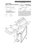
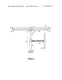
[0017]FIG. 1 shows an anatomic perspective view of a most preferred embodiment of the present invention, it is depicted in the drawing that the supporting rack for a screen is provided on a base 10 thereof with a supporting rod set 20, the supporting rod set 20 is provided at a level in its middle section with a screen positioning set 30 fixed on the back of a screen 100, and the supporting rod set 20 is provided at a position higher than the top of the screen positioning set 30 further with a connecting member 40; the connecting member 40 is provided on its top with a fixing seat 41, and is provided on its two lateral sides each with a transverse connecting port 42 for extending therethrough of a supporting arm 50; the supporting arm 50 is provided on its two ends each with a supporting seat 60 bending to form an "L" shape; and the fixing seat 41 is on the same level as that of the top surfaces of the supporting seats 60 in order that a plate 70 for placing articles can be fixed; and the upper edge of the supporting seats 60 is flared, the contact areas of the supporting seats 60 with the plate 70 for placing articles can be increased. FIG. 2 shows a front view of the supporting rack for a screen after assembling.
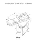
[0018]As shown in FIG. 3, the plate 70 for placing articles can form a platform on the top of the screen 100 for placing peripheral devices or other articles for documentary works, for instance, the plate 70 for placing articles can allow placing thereon a printer 200, two packs of printing papers 300 etc. to have the space above the screen 100 effectively used.
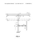
[0019]As shown in FIGS. 1 and 4, the supporting rod set 20 can be provided further with an upper supporting rod 21 and a hollow lower supporting rod 22 slipped over the upper supporting rod 21, when the connecting member 40 is mounted on the upper supporting rod 21, by slipping-connecting of the hollow lower supporting rod 22 with the upper supporting rod 21, the upper supporting rod 21 can be adjusted by raising/descending action; and following raising/descending of the upper supporting rod 21, the plate 70 for placing articles can be adjusted in height in pursuance of the raising/descending of the upper supporting rod 21.
[0020]As shown in FIGS. 2 and 5, the connecting member 40 and the supporting rod set 20 can be matched with each other, when the connecting member 40 is slipped over the top of the upper supporting rod 21, the connecting member 40 can be rotated relatively to the supporting rod set 20 (it is depicted to be rotated relatively to the top of the upper supporting rod 21 in the drawing), the orienting angle of the plate 70 for placing articles can thus be adjusted.
[0021]And as shown in FIG. 1, for the purpose that the screen supporting rack of the present invention can have the characteristic of fast assembling and disassembling, and does not occupy much space after disassembling when it is packed and stored, a user can conveniently assemble it after purchasing; the members of the screen supporting rack of the present invention are fixed with multiple screws, for example: the top of the fixing seat 41 and the tops of the supporting seats 60 are provided each with a screw hole 80, and the plate 70 for placing articles are provided with a plurality of countersinks 71 in corresponding respectively with the screw holes 80, each countersink 71 is provided therein with a screw 81 fixedly screw connected with a corresponding screw hole 80 to it, so that the plate 70 for placing articles can be firmly positioned on the tops of the fixing seat 41 and the supporting seats 60.
[0022]The embodiment described and depicted in the drawings is only for illustrating the present invention, and not for giving any limitation to the scope of the present invention. For example, the base 10 can be a counter balance weight with a heavier weight, and can be a clip able to clamp an edge of a desk, in order that the screen supporting rack for a screen can be firmly positioned on the desk. Therefore, it will be apparent to those skilled in this art that various equivalent modifications or changes without departing from the spirit of this invention shall also fall within the scope of the appended claims.
User Contributions:
comments("1"); ?> comment_form("1"); ?>Inventors list |
Agents list |
Assignees list |
List by place |
Classification tree browser |
Top 100 Inventors |
Top 100 Agents |
Top 100 Assignees |
Usenet FAQ Index |
Documents |
Other FAQs |
User Contributions:
Comment about this patent or add new information about this topic:
Images included with this patent application:
 |  |
 |  |
 |  |
| Similar patent applications: | |
| Date | Title |
|---|---|
| 2011-06-23 | Storing rack for core sample boxes |
| 2009-06-25 | Apparatus and method for supporting an object such as a rifle |
| 2010-06-17 | Supporting device for exhibiting golf club |
| 2012-02-02 | Drying rack for athletic equipment |
| 2009-04-02 | Sectional rack for storage |
| New patent applications in this class: | |
| Date | Title |
|---|---|
| 2016-09-01 | Unit attaching device and indoor unit |
| 2015-03-26 | Hanging closet organizer with rigid adjustable shelves |
| 2014-12-04 | Hanging storage device |
| 2014-09-04 | Hanging shoe compartments with movable shelves |
| 2012-10-25 | Apparatus for suspending at least one object from or above a support surface |
| Top Inventors for class "Supports: racks" | |
| Rank | Inventor's name |
|---|---|
| 1 | Stephen N. Hardy |
| 2 | Wen-Tsan Wang |
| 3 | Gregory M. Bird |
| 4 | Shane Obitts |
| 5 | Kaveh Didehvar |