Patent application title: Seamless connecting drain structure of metallic sink
Inventors:
IPC8 Class: AE03C122FI
USPC Class:
1 1
Class name:
Publication date: 2017-02-02
Patent application number: 20170030059
Abstract:
A seamless connecting drain structure of a metallic sink is provided.
When the metallic sink is installed, a drain pipe or a drain connector as
a drain end of a water outlet of the metallic sink is connected with an
annular ring of the water outlet through a screw sleeve with inner
threads to mesh with outer threads of a connecting sleeve, or a drain
connector having inner threads is directly screwed to the outer threads
of the connecting sleeve to connect with the annular ring. The entire
structure of the water outlet is convenient for the drain pipe or the
drain connector to be connected with the annular ring. Through the
annular ring, the bottom of the metallic sink extends outward to form a
complete configuration, so that the drain end of the water outlet and the
drain pipe or the drain connector are connected seamlessly.Claims:
1. A seamless connecting drain structure of a metallic sink, a bottom of
the metallic sink being formed with a water outlet, the water outlet
extending outward from a wall of the bottom of the metallic sink to form
an annular ring, an outer periphery of the annular ring being fixedly
connected with a connecting sleeve, an outer wall of the connecting
sleeve being formed with outer threads.
2. The seamless connecting drain structure of a metallic sink as claimed in claim 1, wherein the outer threads of the connecting sleeve is screwedly connected with a screw sleeve having inner threads on an inner wall thereof, and a drain pipe is connected to the annular ring of the water outlet through the screw sleeve.
3. The seamless connecting drain structure of a metallic sink as claimed in claim 1, wherein the outer threads of the connecting sleeve is screwedly connected with a screw sleeve having inner threads on an inner wall thereof, and a drain connector is connected to the annular ring of the water outlet through the screw sleeve.
4. The seamless connecting drain structure of a metallic sink as claimed in claim 1, wherein the outer threads of the connecting sleeve is screwedly connected with a drain connector having inner threads therein, enabling the annular ring of the water outlet to be connected with the drain connector.
5. The seamless connecting drain structure of a metallic sink as claimed in claim 1, wherein the connecting sleeve is fixed on an outer surface of the annular ring by welding.
6. The seamless connecting drain structure of a metallic sink as claimed in claim 1, wherein a filter member is provided for plugging the annular ring, the filter member has a filter aperture portion and a recess, the recess is provided with a sink cover for closing the filter aperture portion.
Description:
FIELD OF THE INVENTION
[0001] The present invention relates to a seamless connecting drain structure, and more particularly to a seamless connecting drain structure of a metallic sink to connect with a drain pipe or a drain connector seamlessly so that a water outlet of the metallic sink can be cleaned and maintained easily.
BACKGROUND OF THE INVENTION
[0002] In order to be durable, beautiful or easy for cleaning and maintenance, most kitchen sinks in the market are metallic sinks made of stainless steel. Metallic sinks are used for washing kitchen utensils, dishes, fruit or vegetables. In general, the water outlet of the metallic sink is connected with a drain pipe for draining dirty water. In order to avoid a clog in the drain pipe, the water outlet of the metallic sink is connected with a drain connector, and a filter or a mesh is provided in the drain connector to filter residues in the drainage. In consideration of the cost, the metallic sink is made by sheet metal processing techniques to form a thin casing (thin wall) body. Because the wall of the bottom of the sink is thin, it is not easy to connect a drain connector at the outlet end of the water outlet. For example, a conventional drain connector structure is entitled "a drain connector structure of a kitchen sink". The drain connector is disposed in the sink and extends out from the water outlet of the bottom of the sink. The rim of the drain connector is retained on the surface of the bottom of the sink to cooperate with a packing washer, so that the drain connector is located beneath the bottom of the sink. A locking ring is provided on an outer threaded section of the drain connector for fixing the drain connector to the water outlet. No matter how thin the packing washer is, there is still a gap between the rim of the drain connector and the surface of the bottom of the sink. There will be dirt and filth accumulated in the gap (it is easy to breed mold and bring odor). Furthermore, it is not easy for cleaning and maintenance to affect the appearance of the sink and hygiene.
SUMMARY OF THE INVENTION
[0003] The primary object of the present invention is to provide a seamless connecting drain structure of a metallic sink. A bottom of the metallic sink is formed with a water outlet. The water outlet extends outward from the wall of the bottom of the metallic sink to form an annular ring. The outer periphery of the annular ring is fixedly connected with a connecting sleeve. The outer wall of the connecting sleeve is formed with outer threads. When the metallic sink is installed for use, a drain pipe or a drain connector used as a drain end of the water outlet is connected with the annular ring of the water outlet through a screw sleeve with inner threads to mesh with the outer threads of the connecting sleeve, or a drain connector having inner threads therein is directly screwed to the outer threads of the connecting sleeve to connect with the annular ring of the water outlet. The entire structure of the water outlet is convenient for the drain pipe or the drain connector to be connected with the annular ring. Through the annular ring of the water outlet, the bottom of the metallic sink extends outward to form a complete configuration, so that the drain end of the water outlet and the drain pipe or the drain connector are connected seamlessly. This is easy for cleaning and maintenance.
[0004] Preferably, the connecting sleeve is fixed on an outer surface of the annular ring by welding, so that the connecting sleeve is connected with the annular ring firmly.
[0005] Preferably, a filter member is provided for plugging the annular ring. The filter member has a filter aperture portion and a recess. The recess is provided with a sink cover for closing the filter aperture portion. When the metallic sink is filled with water, the sink cover prevents the water in the metallic sink from be drained from one end of the annular ring of the water outlet. On the contrary, when the sink cover is opened, the dirty water in the metallic sink flows through the end of the annular ring of the water outlet to be drained. The filter aperture portion of the filter member is used to filter impurity to attain a filter effect.
BRIEF DESCRIPTION OF THE DRAWINGS
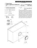
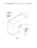
[0006] FIG. 1 is an exploded view of the present invention;
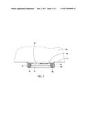
[0007] FIG. 2 is a sectional view of the present invention;
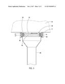
[0008] FIG. 3 is a schematic view of the present invention connected with a drain pipe;
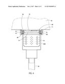
[0009] FIG. 4 is a schematic view of the present invention connected with a metallic drain connector; and
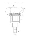
[0010] FIG. 5 is a schematic view of the present invention connected with a plastic drain connector formed by injection molding.
DESCRIPTION OF THE PREFERRED EMBODIMENTS
[0011] Embodiments of the present invention will now be described, by way of example only, with reference to the accompanying drawings.
[0012] The present invention discloses a seamless connecting drain structure of a metallic sink. As shown in FIG. 1 and FIG. 2, a bottom 11 of a stainless steel metallic sink 10 is formed with a water outlet 20. The water outlet 20 extends outward from the wall of the bottom 11 of the metallic sink 10 to form an annular ring 21. The outer periphery of the annular ring 21 is fixedly connected with a connecting sleeve 30. The outer wall of the connecting sleeve 30 is formed with outer threads 31. As shown in FIG. 3 and FIG. 4, when the metallic sink 10 is installed for use, a drain pipe 40 or a stainless steel drain connector 50A (comprising a strainer 51 therein and connecting with a drain duct 52 at a bottom end thereof) used as a drain end of the water outlet 20 is connected with the annular ring 21 of the water outlet 20 through a screw sleeve 60 with inner threads 61 to mesh with the outer threads 31 of the connecting sleeve 30. As shown in FIG. 5, in another embodiment, a drain connector 50B (comprising a strainer 51 therein and connecting with a drain duct 52 at a bottom end thereof) having inner threads therein formed by injection molding and made of a plastic material is directly screwed to the outer threads 31 of the connecting sleeve 30 to connect with the annular ring 21 of the water outlet 20. As shown in FIG. 3, FIG. 4, and FIG. 5, the entire structure of the water outlet 20 is convenient for the drain pipe 40 or the drain connector 50A, 50B to be connected with the annular ring 21. Through the annular ring 21 of the water outlet 20, the bottom 11 of the metallic sink 10 extends outward to form a complete configuration, so that the drain end of the water outlet 20 and the drain pipe 40 or the drain connector 50A, 50B are connected seamlessly. This is easy for cleaning and maintenance.
[0013] According to the aforesaid embodiment, as shown in FIG. 2, the connecting sleeve 30 is fixed an outer surface of the annular ring 21 by welding, so that the connecting sleeve 30 is connected with the annular ring 21 firmly.
[0014] According to the aforesaid embodiment, as shown in FIG. 1 and FIG. 2, a filter member 70 is provided for plugging the annular ring 21. The filter member 70 has a filter aperture portion 71 and a recess 72. The recess 72 is provided with a sink cover 70 for closing the filter aperture portion 71. As shown in FIG. 3, FIG. 4, and FIG. 5, when the metallic sink 10 is filled with water, the sink cover 73 prevents the water in the metallic sink 10 from be drained from one end of the annular ring 21 of the water outlet 20. On the contrary, when the sink cover 73 is opened (not shown in the drawings), the dirty water in the metallic sink 10 flows through the end of the annular ring 21 of the water outlet 20 to be drained. The filter aperture portion 71 of the filter member 70 is used to filter impurity to attain a filter effect.
[0015] Although particular embodiments of the present invention have been described in detail for purposes of illustration, various modifications and enhancements may be made without departing from the spirit and scope of the present invention. Accordingly, the present invention is not to be limited except as by the appended claims.
User Contributions:
Comment about this patent or add new information about this topic:
Images included with this patent application:
 |  |
 |  |
 |  |
| Similar patent applications: | |
| Date | Title |
|---|---|
| 2016-08-11 | Functional architecture pattern for safety related applications |
| 2016-08-11 | Reflecting structure of lamp |
| 2016-08-11 | Memory component having internal read modify-write operation |
| 2016-07-21 | Assembly structure of light unit |
| 2016-07-21 | Assembly structure of spectacle |
| New patent applications in this class: | |
| Date | Title |
|---|---|
| 2022-09-22 | Electronic device |
| 2022-09-22 | Front-facing proximity detection using capacitive sensor |
| 2022-09-22 | Touch-control panel and touch-control display apparatus |
| 2022-09-22 | Sensing circuit with signal compensation |
| 2022-09-22 | Reduced-size interfaces for managing alerts |