Patent application title: DEVICE FOR CONVEYING ELONGATE OBJECTS
Inventors:
IPC8 Class: AB65G1712FI
USPC Class:
1 1
Class name:
Publication date: 2017-01-19
Patent application number: 20170015504
Abstract:
A device (1) designed as a chuck-jaw discharge system for conveying
elongate objects includes two chains (3, 4) equipped with chuck jaws (5).
The chains (3, 4) are driven by two drives (10). Each of the drives (10)
includes an endless roller chain (11), in which toothed edges (13) that
are fastened to the chains (3, 4) equipped with chuck jaws (5) engage.
The roller chains (11) of the drives (10) are coupled to the straight,
adjacent strands of the chains (3, 4) equipped with chuck jaws (5).Claims:
1. Device (1) for conveying elongate objects, in particular pipes or
cables, with two continuous chains (3, 4) that are guided via guide gears
(2), which chains are equipped with chuck jaws (5), and with a drive (10)
for the chains (3, 4), wherein the drive (10) comprises continuous chains
(11), each chain (3, 4) that is equipped with the chuck jaws (5) is
coupled to a chain (11) as a drive, the chains (11) of the drives (10)
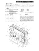
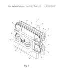
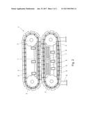
are arranged on both sides of the chains (3, 4) that are equipped with
chuck jaws (5), and toothed edges (13) are arranged on both sides of the
chains (3, 4) that are equipped with the chuck jaws (5), which edges
engage in the chains (11) of the drive (10).
2. Device according to claim 1, wherein the chains (11) of the drive (10) are coupled to strands, which are straight and oriented essentially parallel to one another, of the chains (3, 4) that are equipped with chuck jaws (5).
3. Device according to claim 1, wherein the chains (11) of the drive (10) are in particular multi-barreled roller chains (11).
4. Device according to claim 1, wherein the chains (11) of the drive (10) are arranged symmetrically in relation to the plane in which the chuck jaws (5) adjoin one another in the area of the straight strand of the chains (3, 4).
5. Device according to claim 1, wherein the toothed edges (13), which couple the chains (11) of the drive (10) to the chains (3, 4) that are equipped with chuck jaws (5), are arranged on the lateral surfaces of the chuck jaws (5).
6. Device according to claim 1, wherein the straight strands, facing one another, of the chains (3, 4) that are equipped with chuck jaws (5) are guided by guides (7), and wherein one of the guides (7) can be moved to a position crosswise to the straight strands.
7. Device according to claim 6, wherein a pneumatic adjusting drive, in particular at least one expansion bellows (8), is assigned to the adjustable guide (7).
8. Device according to claim 1, wherein the chains (11) of the drive (10) are designed as two-barreled or multi-barreled chains, and wherein one barrel each of the chains (11) of the drive (10) is coupled to a chain (3, 4) that is equipped with chuck jaws (5).
9. Device according to claim 1, wherein the guide gears (2) for the chains (3, 4) that are equipped with chuck jaws (5) are free-wheeling gears.
10. Device according to claim 1, wherein the guide gears (2) for the chains (3, 4) that are equipped with chuck jaws (5) are mounted securely to the machine frame.
11. Device according to claim 1, wherein the chains (11) of the drives are synchronized with one another, for example by an electric shaft.
Description:
[0001] The invention relates to a device with the features of the
introductory part of the independent claim 1.
[0002] Such devices are known (DE 2 235 359 A).
[0003] In the case of the device that is known from DE 2 235 350 A, the continuous pulling systems are driven by gears that engage in the pulling systems from the inside. In turn, the gears are driven via reducing gears and shafts of a motor. In this case, however, disadvantageous breakdown torque acts on the chuck jaws that are provided on the pulling systems.
[0004] Additional devices for conveying elongate material, such as pipes or cables, are known from DE 26 31 723 A and from U.S. Pat. No. 5,775,415 A.
[0005] It is problematic in known devices when the chains that are equipped with chuck jaws are driven via the guide gears. This creates unfavorable mechanical conditions.
[0006] The object of the invention is to make available an improved device of the above-mentioned type ("chuck-jaw discharge system").
[0007] This object is achieved according to the invention with a device that has the features of claim 1.
[0008] Preferred and advantageous configurations of the invention are subjects of the subclaims.
[0009] Since, in the invention, the drive for the chains, which are equipped with chuck jaws, engages directly on the chains, more favorable lever conditions are produced, and a better synchronization of the two chains of the chuck-jaw discharge system can be achieved.
[0010] For the drive, the invention calls for chains, in particular chains in the form of roller chains, to be provided, which are coupled to the chains that are equipped with chuck jaws.
[0011] The coupling is done with toothed edges, which are fastened to the chain links that carry the chuck jaws, and in which the chains of the drive engage.
[0012] For the drive of the chains that are equipped with chuck jaws, a separate drive in the form of a chain, e.g., a roller chain, is assigned to each chain that is equipped with chuck jaws.
[0013] The drives, designed as chains, of the chains that are equipped with chuck jaws can be synchronized with one another in an arbitrary manner.
[0014] It can be provided that the drives are synchronized with one another by an electric shaft.
[0015] The invention calls for the chains as drives for the chains that are equipped with chuck jaws to be provided on both sides of the chains that are equipped with chuck jaws. In this case, there can be provided, on each side, one chain each that is coupled to two chains that are equipped with chuck jaws, or, on each side, two chains, each of which is coupled to a chain that is equipped with chuck jaws.
[0016] The drive according to the invention is simpler and less susceptible to breakdown than a drive with the guide gears of the chains equipped with chuck jaws.
[0017] In one embodiment of the device according to the invention, the guide gears are securely mounted in the machine frame of the device according to the invention.
[0018] The traction between chuck jaws and the object to be conveyed that is necessary for the transport of the elongate object is achieved by at least one of the guide rails, on which the insides of the straight strands of the two chains that are equipped with chuck jaws rest, for example using pneumatic means, such as expansion bellows, being pressed onto the straight strand of the opposite chain that is equipped with chuck jaws.
[0019] Additional details and features of the invention follow from the description below of an embodiment based on the drawings. Here:
[0020] FIG. 1 shows a device according to the invention in an oblique view, and
[0021] FIG. 2 shows a device according to the invention in side view (without a drive).
[0022] A device 1 according to the invention for conveying elongate objects, in particular pipes or cables, comprises two continuous chains 3, 4 that are guided via guide gears 2. Each of the chains 3, 4 is equipped with a number of chuck jaws 5. The chuck jaws 5 adjoin one another with essentially zero play in the straight sections (strands) of the chains 3, 4. The chuck jaws 5 adjoin the elongate object (pipe or cable) to be conveyed and are pressed against the object, so that the friction, necessary for the conveying of the object, between chuck jaws 5 and object is provided.
[0023] The chains 3, 4 of the device 1 according to the invention, equipped with chuck jaws 5, run via the non-driven, i.e., free-wheeling, guide gears 2, which are mounted in a stationary manner in the machine frame 6.
[0024] Guides 7, which adjoin the insides of the chains 3, 4, are assigned to the straight strands, adjacent to one another (cf. FIG. 2), of the chains 3, 4 that are equipped with chuck jaws 5.
[0025] In this connection, it is preferably provided within the scope of the invention that one of the guides 7, the guide 7 in the embodiment shown, of the straight strand of the upper continuous chain 3 that is equipped with chuck jaws 5, is mounted in a stationary manner in the machine frame 6.
[0026] The guide 7 for the lower chain 4, equipped with chuck jaws 5, is loaded on the straight strand of the upper chain 3, equipped with chuck jaws 5, using expansion bellows 8 to which pressurized gas (air) can be applied. Thus, the necessary friction between the elongate object to be conveyed and the chuck jaws 5, which is necessary for the problem-free and uniform conveying of the elongate object, is achieved.
[0027] In the embodiment shown, drives 10 that are arranged on sides that are opposite to one another in relation to the chains 3, 4, i.e., on both sides of the chains 3, 4, are assigned to the chains 3, 4. Each of the drives 10 comprises a multi-barreled roller chain 11, to which a drive motor 12 is assigned. The drive motors 14 of the two drives 10 are (electrically) coupled to one another. On the lateral surfaces of the links, of the chains 3, 4 that are equipped with chuck jaws 5, toothed edges 13 are arranged, in which the roller chain 11 engages, so that the chains 3, 4 that are equipped with chuck jaws 5 are driven synchronously. The chains 11 of the drives 10 engage in the straight strands of the chains 3, 4 that are equipped with chuck jaws 5, i.e., in the area where the chuck jaws 5 adjoin one another or rest on the object to be conveyed.
[0028] The design according to the invention makes it possible for the toothed edges 13 to be arranged essentially in the middle of the chuck jaws 5, so that favorable lever ratios are produced and no breakdown torque occurs on the chuck jaws 5 because of the drives 10.
[0029] Since, as in the embodiment shown, both chains 3, 4 that are equipped with chuck jaws 5 are driven by a common drive 10 with one multi-barreled roller chain 11 each, a synchronous movement of the chains 3, 4 equipped with chuck jaws 5 is ensured.
[0030] In summary, an embodiment of the invention can be described as follows.
[0031] A device 1 that is designed as a chuck-jaw discharge system for conveying elongate objects comprises two chains 3, 4 that are equipped with chuck jaws 5. The chains 3, 4 are driven by two drives 10. Each of the drives 10 comprises a continuous roller chain 11, in which toothed edges 13 fastened to the chains 3, 4 that are equipped with chuck jaws 5 engage. The roller chains 11 of the drives 10 are coupled to the straight strands, adjoining one another, of the chains 3, 4 that are equipped with chuck jaws 5.
User Contributions:
Comment about this patent or add new information about this topic:
Images included with this patent application:
 |  |
 |
| Similar patent applications: | |
| Date | Title |
|---|---|
| 2016-08-25 | Peristaltic pump comprising angularly variable pressure rollers |
| 2016-08-25 | Control device for internal combustion engine |
| 2016-08-25 | Real time machine learning based predictive and preventive maintenance of vacuum pump |
| 2016-08-11 | Downloading media objects |
| 2016-08-25 | Device for cutting hair |
| New patent applications in this class: | |
| Date | Title |
|---|---|
| 2022-09-22 | Electronic device |
| 2022-09-22 | Front-facing proximity detection using capacitive sensor |
| 2022-09-22 | Touch-control panel and touch-control display apparatus |
| 2022-09-22 | Sensing circuit with signal compensation |
| 2022-09-22 | Reduced-size interfaces for managing alerts |