Patent application title: DISTANCE MARKING SYSTEM FOR GOLF CLUBS
Inventors:
Daniel G. Cheresko (Brighton, MI, US)
IPC8 Class: AA63B6016FI
USPC Class:
1 1
Class name:
Publication date: 2016-10-13
Patent application number: 20160296812
Abstract:
A yardage identifying attachment for a golf club grip end, having a disk
shaped body adapted to being attached to an end face of the club grip
end. An insert secures within each of the disk shaped bodes for
exhibiting a yardage indicia associated with a typical driving distance
of a selected golf club. A multi-sided and multi-layered wheel
construction provides an aligning representation of a given club type to
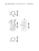
an expected driving distance, with a predicted driving performance of the
remaining clubs being aligned with other calculated yardages associated
with the circumferential disk representation. A plurality of flexural and
attachable sleeves, such exhibiting and open split edge, are also
provided and which can be attached to the foot end of the club shaft. The
present invention also discloses packaging for combining all of the
variants described herein along with instructions for use.Claims:
1. A yardage identifying attachment for a golf club grip end, comprising:
a disk shaped body adapted to being attached to an end face of the club
grip end; and an insert for securing within each of the disk shaped bodes
for exhibiting a yardage indicia associated with a typical driving
distance of a selected golf club.
2. The attachment as described in claim 1, further comprising a plurality of individual disks, each exhibiting at least one yardage indicia.
3. The attachment as described in claim 2, each of said disks further comprising a plurality of yardage indicia arranged in a circumferential fashion.
4. The attachment as described in claim 3, said body further exhibiting an arcuate window in an upper surface for revealing a selected yardage indicia.
5. The attachment as described in claim 4, further comprising a tactile rotating identification structure established between said body and said disks not limited to 60 degree.
6. The attachment as described in claim 1, said body further comprising an anchor extending from an underside surface adapted to engage a vent hole of the club grip end.
7. The attachment as described in claim 6, said anchor further comprising one or more exteriorly spiraling taper patterns.
8. The attachment as described in claim 2, further comprising said disks each exhibiting a generally circular shape with opposite end projecting alignment tabs configured to align with and seat within notched upper side locations of said body.
9. The attachment as described in claim 8, said notched locations being defined between arcuate separated outer walls configured upon said upper side of said body in order to seat the selected yardage disk.
10. The attachment as described in claim 9, further comprising said yardage disks being reversible.
11. The attachment as described in claim 6, said body further comprising a concave inner surface.
12. A golf yardage dial for determining a second club selection based upon a predicted driving distance of any other club, comprising; an inner disk having a first diameter exhibiting a first circumferential array of golf club designations and an outer inter-rotatable disk having a second larger diameter and sandwiched against said inner dsk, said outer dsk indicating a second circumferential array of driving distances indicated in yardage; and upon rotationally aligning a known club designation with a known driving distance, additional club designations and driving distances being indicated by alignment between said disks.
13. The dial as described in claim 12, said inner disk further comprising front and back dials sandwiching opposite faces of said outer disk.
14. The dial as described in claim 12, further comprising said inner disk indicating each of fairway wood (FW), irons 3-9, pitching wedge (PW), GW, SW, and LOB desigantions.
15. A combination kit for providing an expected driving distance of a ball by a golf club, comprising: a plurality of yardage identifying attachments for a golf club grip end, including a disk shaped body adapted to being attached to an end face of the club grip end and an insert for securing within each of said disk shaped bodes for exhibiting a yardage indicia associated with a typical driving distance of a selected golf club; and an equal plurality of elongated sleeves adapted to being attached to a foot end of each club, said sleeves each including a flexural elongated and generally cylindrical shaped body exhibiting a resilient material construction, said body having an open and linearly extending split edge which can be flexed in an outward/open direction so as to be adapted to attach to the club shaft, with the natural biasing force of the resilient material acting to hold the collar closed against the club shaft, a yardage indicia applied to a surface of said body, typically matching that of said grip end mounted inserts, and which is visible to a user when the club is retained within a golf bag.
16. The kit as described in claim 15, said split edges each further comprising first narrowed and parallel extending segments with a further interconnected slip start taper segement defining leading edges for installation around the circumference of the base of the golf club shaft near the bottom club end and in a manner which does not result in damage or over flexing of the collar.
Description:
CROSS-REFERENCE TO RELATED APPLICATIONS
[0001] This Application claims the benefit of U.S. Provisional Application 62/145,928 filed on Apr. 10, 2015, the contents of which are incorporated herein in its entirety.
FIELD OF THE INVENTION
[0002] The present invention relates generally to yardage identification systems for use with golf clubs. More particularly, the invention teaches a plurality of indicia identification and generally disk shaped attachments, these being attached in one non-limiting application to the grip end of each club shaft for the purpose of providing a recommended driving yardage or distance associated with the particular club.
BACKGROUND OF THE INVENTION
[0003] The prior art is documented with various types of identification marking systems, in particular for use with golf clubs. A first example of this is depicted in the identification mark system of EP 0 320 212, to Lockerman, which teaches a disc-like body portion with a cylindrical ancho means formed on the bottom surface of the body member. An enlarged conical head is formed on the bottom of the cylindrical anchor member is forced through a hole in a resilient member to snugly fit the anchor member within the hole. Removal of the marker without permanent disfigurement of the resilient member is therefore prevented. A protective collar is formed on the top surface of the body member and identification indicia are engraved within the space on the top surface of the body member that is protected by the annular collar.
[0004] U.S. Pat. No. 2,986,937, to Chapman, teaches a lineal yardage meter attachment for golf clubs in which in combination, includes a tubular housing having a constant internal diameter, an aperture in the lower end portion of the housing and means for detachably securing the housing to the shaft of a golf club. A downwardly tapered indicating member is slidably mounted in the housing for endwise movements therein, the indicating member having lineal yardage indicia thereon and frictional engagement with the interior surfaces of the housing. The indicating member projects through the aperture in the housing during the swinging movement of the golf club by virtue of the centrifugal force imposed on the indicating member, and whereby centrifugal force is transposed into readable lineal yardage.
[0005] U.S. Pat. No. 4,822,052, to Dimmick, teaches a matched set of golf club identification markers for each golf club in the golfer's bag, each including a disc-like body portion with a cylindrical anchor member formed on the bottom surface of the body member. An enlarged conical head is formed on the bottom of the cylindrical anchor member and is forced through the vent hole on the golf club grip to snugly fit the anchor member within the vent hole. A protective collar is formed on the top surface of the body member and identification indicia are engraved within the space on the top surface of the body member that is protected by the annular collar. For the putter, a removable ball position indicator is added to the identification marker. The ball position indicator has a recess formed on the bottom surface for engaging a snap fastener-like head on the upper surface of the body. For the putter identification marker, the annular protective collar is discontinuous so that the edge of the ball position indicator may be reached to remove the ball position indicator from the marker to place it on the putting green.
SUMMARY OF THE INVENTION
[0006] The present invention teaches a yardage identifying attachment for a golf club grip end, having a disk shaped body exhibiting a yardage indicia associated with a typical driving distance of a selected golf club. A plurality of individual disks are providing, each exhibiting at least one yardage indicia. The disks can each exhibiting a generally circular shape with opposite end projecting alignment tabs configured to align with and seat within notched upper side locations of the body. The notched locations are defined between arcuate separated outer walls configured upon the upper side of the body in order to seat the selected yardage disk.
[0007] In a preferred embodiment, each of the disks further exhibits a plurality of yardage indicia arranged in a circumferential fashion. The body includes a concave inner surface and can further exhibit an arcuate window in an upper surface for revealing a selected yardage indicia. A tactile rotating identification structure can be established between the body and the disks not limited to 60 degree. In a further variant, the body further includes an anchor extending from an underside surface. The anchor further includes one or more exteriorly spiraling taper patterns. Other features include the yardage disks being reversible.
[0008] Additional variants include a multi-sided and multi-layered wheel construction for providing an aligning representation of a given club type to an expected driving distance, with a predicted driving performance of the remaining clubs being aligned with other calculated yardages associated with the circumferential disk representation. A plurality of flexural and attachable sleeves, such exhibiting and open split edge, are also provided and which can be attached to the foot end of the club shaft. The present invention also discloses packaging for combining all of the variants described herein along with instructions for use.
BRIEF DESCRIPTION OF THE DRAWINGS
[0009] Reference will now be made to the attached drawings, when read in combination with the following detailed description, wherein like reference numerals refer to like parts throughout the several views, and in which:
[0010] FIG. 1A is a representation of a plurality of yardages associated with identification disks, and FIG. 1B is a further representation of clubs associated with the identification disks according to one non-limiting variant of the inventions;
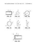
[0011] FIGS. 2A-2H present a series of side, end and cutaway views of selected yardage disk design including mounting anchor variants for securing to the rubberized end surface of the selected club shaft;
[0012] FIGS. 2I-2O present a further series of side and plan views of a further selected yardage disk supporting body according to an alternate configuration and depicting both screw and push in variants associated with the disk supporting bodies, these further including a tapered side profile for compensating for variances in the dimensions of the grip underside;
[0013] FIG. 3 is an illustration of a plurality of snap covers forming part of an alternate variant and which are adapted to being engaged to the rubberized ends of the club shafts;
[0014] FIG. 4 succeeds FIG. 3 and illustrates a plurality of yardage identification disks which are incorporated with the snap covers into the club shaft ends, the disks each exhibiting a plurality of yardages according to a determined range associated with the selected club, one of which being selected for that club according to given criteria;
[0015] FIG. 5 is a combination of FIGS. 3 and 4 according to a determined range of clubs LW-FW;
[0016] FIG. 6 is a pair of side and end views of a selected club grip end;
[0017] FIGS. 7A-7C provide a series of yardage disk, top view and bottom view representations according to the present design;
[0018] FIGS. 8A-8B respectively provide a pair of section views of a first flattened disk design and a sectional side view of an alternate anchor configuration;
[0019] FIG. 9A is a partial side cutaway depicting a selected disk in press fit attachment to a rubberized grip end surface of the club; and
[0020] FIGS. 10-12 provide a series of perspective views of an indicia identification attachment according to a further preferred embodiment;
[0021] FIGS. 13A-13G depict a series of views of an alternatively configured golf yardage dial or insert in use with the present invention;
[0022] FIGS. 14A-14D depict a series of views of a golf club distance sleeve forming a further variant of the present invention and which can be flexed to attach to the club shaft; and
[0023] FIGS. 15-18 present a series of front, back, side cutaway and perspective views of a packaging version of the present invention integrating a collection of attachable end face disks, and flex sleeves for use with a collection of golf clubs.
DETAILED DESCRIPTION OF THE PREFERRED EMBODIMENTS
[0024] Referring now to the attached illustrations, the present invention teaches a plurality of indicia identification and generally disk shaped attachments, these being attached in one non-limiting application to the grip end of each club shaft for the purpose of providing a recommended driving yardage or distance associated with the particular club. As will be described, the present inventions provide the ability to establish typical driving distances for each individual club, and which can include establishing yardage ranges in the form of plural distance indicia identifications which can be arrayed about a circumference of a disk shaped surface of the disk, with a selected one of the distance indicia markings bring revealed by a snap cover with aligning aperture location. As will be additionally described, other variants can include a flexurally attachable collar portion which can be attached to the shaft and which exhibits the desired yardage indicia.
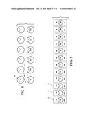
[0025] Referring to FIG. 1A, a representation is shown of a plurality of yardage disks or inserts, 2, 4, 6 et seq. are shown and which are associated with individual club identification disks, and FIG. 1B is a further representation of clubs 3, 5, 7, et seq., associated with each of the identification disks according to one non-limiting variant of the inventions. As shown in FIG. 1A, the yardage ranges can vary from 15 to 235 yards, with the club selections ranging from various wedges LW, GW, SW, PW, through descending irons 9-3, concluding with royal collection (RC) and fairway wood (FW) clubs. For purposes of explanation, FIGS. 1A and 1B are intended to be representative typical yardage and club designations without limitation to any particular application.
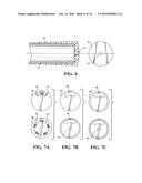
[0026] Proceeding to FIGS. 2A-2H, a series of side and plan views are shown of a selected yardage disk design including mounting anchor variants for securing to the rubberized end surface of the selected club shaft. This can include an optional anchor configuration, see at 10 in FIG. 2A for piercing the disk 2 (shown in side profile in FIG. 2B). The anchor 10 can further, in one non-limiting construction, have a generally 0.125'' diameter shaft which screws through a selected indicia identifying disk 2, 4, 6, et seq. positioned underneath the disk body, the screw proceeding to engage the club upon passing into a vent hole arranged in a top of the golf club grip (see at 12 mounted over shaft end 14 as further shown in FIG. 2H, such being further represented in the combined side and end cutaway views of FIG. 6).
[0027] The anchor 10 includes one or more exteriorly spiraling taper patterns and which forms an integral portion of a circular and three dimensional body associated with the disk attachment structure. The yardage disks (e.g. at 2) exhibit a generally circular shape with opposite end projecting alignment tabs 18 and 20 (FIG. 2C), these configuring to align with and seat within notched upper side locations 22 and 24 of the body 16, the notched locations being defined between arcuate separated outer walls 26 and 28 (see FIGS. 2D) configured upon the upper surface of the body in order to seat the selected yardage disk (see example of indicia marker 150 in FIG. 2G which is structurally identical to that depicted in FIG. 2D).
[0028] Although not shown, the yardage disks can be reversible, such as which can present either or both of an alternating color scheme (black on white or while on black) or another yardage indicia according to a related range for the given club. It is also understood that any number of yardage disks (also termed inserts) can be provided in a stacked or plural fashion according to a given club design and within the intended scope of the present inventions.
[0029] As further shown, the indicia revealing yardage disks can be constructed of a flexible paperboard or combination paper and laminated or clear plastic covering, such having a minimal (0.03'') thickness in combination with a plan disk outer diameter (0.90'') and alignment tab outer diameter (1.05''), the tabs having an linear outer surface dimension of 0.325''. The club grip end mounted disk bodies, again at 16, each further include solid (smooth edge) side and bottom surfaces and, as will be described in further detail in reference to the succeeding illustrations, the underside of the circular body can be either flat or concave in order to more closely align with the profile of the rubberized grip end surface of the club.
[0030] FIGS. 21-20 presents a further series of side and plan views of a further selected yardage disk supporting body 30 according to an alternate configuration for attaching to the grip end 12 of the club shaft 14 (see in cutaway side plan view in FIG. 2I and as further depicted in end view in FIG. 2J with an optional through aperture 13 for receiving the stem 35 and associated embossment 36 of the body 30). The indicia disk supporting body 30 (such depicted in FIG. 2K in exterior plan view illustrating an outer rim or skirt 33 and further in exterior rotated fashion in FIG. 2L) and depicting both screw and push in variants (see at 35 in FIG. 2N and further at 35' in FIG. 20) associated with the disk supporting bodies. In each case, a tapered side profile of the body 30 exhibits a concave or cupped underside (such shown at 31 in a cross sectional cutaway of FIG. 2M as compared to FIG. 2N which illustrates the side plan view of the body 30 with the encircling outer diameter rim).
[0031] The tapered construction with outer rim wall operates to compensate for variances in the dimensions of the grip underside (not shown). Similar to the progression of views in FIG. 2A-2H), the cap design of the body 30 exhibits a circular profile with either of upper configured or undercut walls 32 and 34 (see again FIG. 2L), these similar to those depicted at 26 and 28 in FIGS. 2D & 2G and within which can be resistively or biasingly seated the selected yardage indicia disks, 2, 4, 6, et seq.
[0032] As with the variant of FIGS. 2A-2H, the yardage indicia markers and associated supporting bodies can be screwed or push pin inserted into the club end grips (such as again through the central most disposed vent holes in the grip end surface). The projecting anchor again includes a stem 35 (a further variant being again shown at 35' in FIG. 2I), the stem 35 also including an end supported and bulbous portion 36, such as which can be press fit through the vent hole of the grip. The concave or tapered underside of the disk attachment body can further be reconfigured as desired to accommodate other grip designs and in order to minimize the existence of any gap or separation distance with the club grip. In addition to that shown, a number of other potential configurations are possible for reshaping the club grip end attachment bodies for in turn securing thereto the indicia yardage disks.
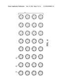
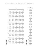
[0033] Proceeding to FIG. 3, an illustration is shown of a plurality of snap covers 38, 40, 42, et seq. forming part of an alternate variant of club grip attachable bodies. In one non-limiting variant, any number of snap covers can be provided for each club (identified in one non-limiting collection as irons 3-9, PW, SW, GW, LW and FW). As further shown, each of the snap covers exhibits an arcuate extending slot shaped aperture, see at 44 for selected disk 38. In one non-limiting embodiment, a pair of each snap covers can be provided for each of the twelve indicated clubs, totaling twenty four pieces per set.
[0034] FIG. 4 succeeds FIG. 3 and illustrates a plurality of yardage identification disks 46, 48, 50, et seq. which are incorporated with the snap covers 38, 40, 42 et seq. into the club shaft ends. The disks each exhibit a plurality of yardages (see exemplary readings 195, 200, 205, 210 and 215 for selected disk 46) according to a determined range associated with the selected club, one of which being selected for that club according to given criteria. According to the illustrated variant, a total of thirty-two pieces are shown with each depicting four yardage markings.
[0035] As further shown, the arrangement of the yardage readings (in an outwardly facing circumferential pattern) is such that a selected one of the readings is exposed upon rotating the identification disk to reveal the selected reading through the aperture or window in the associated snap cover, and further such as representatively shown in FIG. 5. It is further envisioned that the club end mounted disk bodies and yardage identification inserts can be designed such that each body provides a tactile click or the like (in one instance at 60 degree rotational intervals for the yardage disks).
[0036] FIG. 5 further presents a combination of FIGS. 3 and 4 according to a determined range of clubs FW, irons 3-9, PW, SW, GW and LW (see at 52, 54, 56, et seq.) and further in which an uppermost (lower) and lowermost (upper) yardage readings are provided. FIG. 6 again illustrates an enlarged combination linear cutaway and end view of the rubber grip 12 applied over the steel shaft 14 of the golf club and again showing the optional end aperture 13 (optionally including a 0.125'' diameter) for receiving the selected indicial marking body 16 or 30 (see also club grip top in rotated plan end view).
[0037] FIGS. 7A-7C combine the aspects of FIGS. 3 and 4 in order to provide a series of yardage disk 36 (FIG. 7A), top view 36' (FIG. 7B) and bottom view 36'' (FIG. 7C) representations according to the present design. As further shown, tactile embossments 53 on the selected indicia disk and combination supporting body (as generally represented) provide for secure rotational adjustments (such as at 60 degree increments) of the indicia disk in order for the selected reading to be easily visible through the indicated window 55
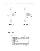
[0038] FIG. 8A further provides a section view of a first flattened disk design 58 (see first variation of press fit stem 59) and FIG. 8B depicts a sectional side view of an alternate anchor configuration (see stem 60 with taper and thread 62 arrangement). An alternate anchor configuration 66 is shown in FIG. 9A which is similar to that previously illustrated in FIGS. 2H, 2I and 2O and which integrally projects from concave inner surface 64 of the indicated attachment body. The attachment disk provides like section and profile views of a further tapered disk design which is configured to closely align with the end surface of the rubberized club grip with minimal gap. The anchor variant 66 further exhibits a sharpened point in combination with a tapered locking underside separating the stem from an underside shoulder of an enlarged end 68. As is again shown in FIG. 9A, the partial side cutaway depicts selected disk 64 engaged in a press fit attachment to a rubberized grip end surface of the club in a manner similar to that previously described.
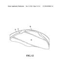
[0039] FIGS. 10-12 illustrate a variety of perspective views of an indicia disk attachment device according to a further preferred embodiment. As shown in FIG. 10, a one piece molded plastic body 70 includes a generally annular shape with a projecting anchor portion 72 extending from an underside of the body via a narrowed neck 74, such further including side reinforcing portions 75 or the like terminating in a pseudo conical fastener configuration for retaining the disk in seated fashion with the rubber grip end 12 of the club shaft 14 and its associated vent hole 13.
[0040] As further shown, the annular main body 70 exhibits an inwardly angle or taper communicating with a reverse and downwardly angled inner, wall portion 76 communicating with a top circular surface 78, this in turn seating a selected yardage disk according to the previously disclosed variants (not shown for purposes of ease of illustration). Notched edge locations are shown at 80 and 82, similar to as previously depicted, and which align with and seat the end projecting alignment tabs (again at 18 and 20 in FIG. 2) associated with a given yardage disk.
[0041] The circular inner edge configuration associated with inner wall portion 76 may further exhibit any of clips, seating detents or the like at spaced inner circumferential locations and which are suited for releasably engaging a selected yardage disk. It is also envisioned that either the shaping of the body 70 or the manner of engaging the selected yardage disk may be modified from that shown without departing from the scope of the invention.
[0042] Additional variants contemplate other ways of securing the disk supporting bodies to the end surface of the golf club grip not requiring an anchor, such not limited to other types of clip or detent structure. While the disk body and anchor structure illustrated provides for removability when engaged through the vent hole in the end surface of the rubberized grip, it is also envisioned that other variants of disk bodies without projecting anchors can be adhesively or otherwise secured to the club end structure.
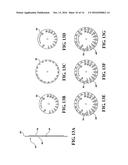
[0043] Proceeding to FIGS. 13A-13G, a series of views are shown of an alternatively configured golf yardage dial 84 (also termed an adjustable wheel) or insert in use with the present invention. These can replace the indicia disks as shown in the previous embodiments for attachment to the golf club grip end or can be utilized as separately carryable item.
[0044] In the illustrated embodiment, the dial 84 can include a plastic laminated or like (see side view of FIG. 13A) multi-layer construction including each of a. front (20-180 yard) club identification disk 86, a middle (6-220 yard) disk 88 and a backside (80-200 yard) club identifying disk 90. As shown, each of the front 86 and back 90 yard disks have a smaller diameter relative to the middle or outer disk 88. The front 86 and back 90 disks also include circumferentially spaced apart settings for each of fairway wood (FW), irons 3-9, pitching wedge (PW), GW, SW, and LOB and, upon aligning any known driving distance of a first club to a yardage setting associated with the outer circumferential array, a predicted driving distance of all the remaining indicated clubs is also provided.
[0045] FIGS. 13E-13G depict combined variations of front, middle and back yardage dials, both with and without color backgrounds. FIG. 13E depicts a variant 88' of an outer yardage dial (20-180 yards) in combination with the club indication dial 86, with FIG. 13F depicting a front view of an outer dial 88'' with a colored background and FIG. 13G a further variant 88''' of colored outer dial from a backside illustration (the front and back side views depicting a rotatable arrangement of the golf yardage dial).
[0046] In this manner, the front 80 and back 90 dials are sandwiched on opposite faces of the inner dial 88, 88', 88'', 88''', such being held in inter-rotating relationship by a rivet 89. As further best again shown by FIGS. 13E-13G, rotating the selected front/back inner dial (86 or 90 depending upon which side of the dial is being displayed) causes the club indications to line up to the desired yardages.
[0047] In this manner, a golfer who may hit a certain club, wedge, iron, etc., with a given degree of confidence of distance can utilize this tool in order to accurately determine an expected driving distance of other clubs in relation to a desired yardage. This includes in the front face designation of FIG. 13F designations for each of lob (lobbing wedge) at thirty yards, sw (short or sand wedge) at fifty yards, gw (gap wedge) at sixty yards, nine iron at eighty yards, eight iron--ninety yards, seven iron--one hundred yards, six iron--one hundred and ten yards, five iron--one hundred and twenty yards, four iron--one hundred and thirty yards, three iron--one hundred and forty yards, and fw (fairway wood)--one hundred and sixty yards.
[0048] Rear or back face designation (FIG. 13G) likewise depicts a sixty to two hundred and twenty yard guide with accompanying designations for lob--seventy yards, sw--ninety yards, gw--one hundred yards, pw--one hundred and ten yards, nine iron--one hundred and twenty yards, eight iron--one hundred and thirty yards, seven iron--one hundred and forty yards, six iron--one hundred and fifty yards, five iron--one hundred and sixty yards, four iron--one hundred and seventy yards, three iron--one hundred and eighty yards, and fw--two hundred yards.
[0049] FIGS. 14A-14D depict a series of views of a golf club distance sleeve, see at 92, forming a further variant of the present invention. The sleeve 92 is intended to be provided additional or alternative to the end mounted yardage indicia and/or the separately hand held yardage adjustable disks (wheel) and is provided with an overall elongated and generally collar shape with a split open (see opposing edges 94 and 96).
[0050] In one preferred application, a modification of the present kit (shown in FIGS. 15-18) can include an equal plurality of both club grip end attachments as well as foot end resistive sleeve/collar attachments 92, such exhibiting matching yardage indicia for each associated club. The split sleeve is typically constructed of a flexural plastic or the like with a generally cylindrical shape having an open split linear edge and which can be flexed in an outward/open direction in order to attach to the club shaft, with the natural biasing force of the resilient material acting to hold the collar closed at the base of the club shaft.
[0051] As further shown in the non-limiting example of the collar 92, the split edges 94 and 96 include a first narrowed and parallel extending segment with a further interconnected slip start taper segement 94' and 96', these further defining leading edges for installation around the circumference of the base of the golf club shaft near the bottom club end and in a manner which does not result in damage or over flexing of the collar 92. FIG. 14D further depicts a rotated plan view of the collar 92 in FIG. 14B and by which a yardage designation 98 is provided, such as in bold text on the non-linearly split and arcuate exhibiting surface of the collar.
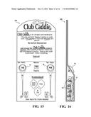
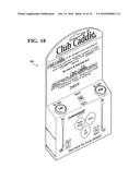
[0052] FIGS. 15-18 present a series of front, back, side cutaway and perspective views of a packaging version, generally at 100, of the present invention which combines any collection or combination of attachable end face bodies (16, 30, 70 et. seq. with some of these also being configured for projecting attachment to the exterior of the packaging as in the case of the body 70), and flex sleeves 92 for use with a collection of golf clubs. FIGS. 15 and 17 provide additional instructional information for the kit versions of the packaged collection and which further provides the user with the ability to customize the indicia inserts by writing in alternate yardage designations. With the further use of the collars (sleeves) 92 at the foot end of the club (see again packaging illustrations of FIGS. 15, 17 and 18), the user can see the expected yardage of the club before pulling from bag. As further understood, the tabs (such defined to include both the club grip end attachable bodies and the associated indicia inserts) and sleeves can be utilized in a combined package for customizing the club set to the particular driving distance performance of the golfer.
[0053] Having described my invention, other and additional preferred embodiments will become apparent to those skilled in the art to which it pertains, and without deviating from the scope of the appended claims. At a minimum, this can include reconfiguring the attachment disks as digital readout element which can be attached to the club grip end in order to provide the desired distance readouts to the user.
[0054] In one expanded variant, such a digital attachment can include any form of GPS location and transmitting functionality which, in addition to providing typical driving distances associated with the selected club, can also provide a form of notice or warning if the user is attempting to utilize a type of club for a stroke which is inconsistent with a recommended club strategy that may also be programmed into the digital attachable device. It is also envisioned that a redesigned club grip can include the indicia mounted structure as an integral part of its structure, such further envisioning such as a coextrude hard plastic portion formed with the end surface of an attachable grip and which can receive any number of yardage identification disks in the manner shown and described herein.
User Contributions:
Comment about this patent or add new information about this topic:
Images included with this patent application:
 |  |
 |  |
 |  |
 |  |
 |  |
 |  |
 |  |
 |
| New patent applications in this class: | |
| Date | Title |
|---|---|
| 2022-09-22 | Electronic device |
| 2022-09-22 | Front-facing proximity detection using capacitive sensor |
| 2022-09-22 | Touch-control panel and touch-control display apparatus |
| 2022-09-22 | Sensing circuit with signal compensation |
| 2022-09-22 | Reduced-size interfaces for managing alerts |