Patent application title: APPARATUS HAVING PILLOW CASE AND A CADDY SECTION
Inventors:
Cindy Simpson Jurado (Calgary, CA)
Judd Jurado (Calgary, CA)
IPC8 Class: AA47G902FI
USPC Class:
1 1
Class name:
Publication date: 2016-10-13
Patent application number: 20160296046
Abstract:
An apparatus is for a pillow. The apparatus includes a pillowcase
presenting end sections that are spaced apart from each other. The
pillowcase provides a pillow pocket configured to receive, at least in
part, the pillow. The pillow pocket extends between the end sections of
the pillowcase. A first caddy section provides a first caddy pocket. A
second caddy section provides a second caddy pocket. The first caddy
section and the second caddy section extend from the end sections of the
pillowcase. This is done in such a way that the pillow, once received in
the pillowcase, is positioned and extended between the first caddy
section and the second caddy section.Claims:
1. An apparatus for a pillow, the apparatus comprising: a pillowcase
presenting end sections, the end sections being spaced apart from each
other, and the pillowcase providing a pillow pocket being configured to
receive, at least in part, the pillow, and the pillow pocket extending
between the end sections of the pillowcase; a first caddy section
providing a first caddy pocket; a second caddy section providing a second
caddy pocket; and the first caddy section and the second caddy section
extending from the end sections of the pillowcase in such a way that the
pillow, once received in the pillowcase, is positioned and extended
between the first caddy section and the second caddy section.
2. The apparatus of claim 1, wherein: the pillowcase provides a first rear pocket being positioned at a rear section of the pillowcase.
3. The apparatus of claim 1, wherein: the pillowcase provides: a first rear pocket; and a second rear pocket, and the first rear pocket and the second rear pocket are positioned at a rear section of the pillowcase.
4. The apparatus of claim 3, wherein: the first rear pocket and the second rear pocket extend downwardly from a top section of the pillowcase.
5. The apparatus of claim 1, wherein: the first caddy section and the second caddy section are removably detachable from respective end sections of the pillowcase.
6. The apparatus of claim 1, wherein: the first caddy section includes a first connector configured to connect the first caddy section to a respective end section of the pillowcase.
7. The apparatus of claim 1, wherein: the second caddy section includes a second connector configured to connect the second caddy section to a respective end section of the pillowcase.
8. The apparatus of claim 1, wherein: the first caddy section includes a first connector configured to connect the first caddy section to a first end section of the pillowcase; and the second caddy section includes a second connector configured to connect the second caddy section to a second end section of the pillowcase.
9. The apparatus of claim 8, wherein: the first connector includes a first touch fastener, in which a portion of the first touch fastener is positioned along one side of the first caddy section, and a corresponding portion of the first touch fastener is attached to the first end section of the pillowcase; and the second connector includes a second touch fastener, in which a portion of the second touch fastener is positioned along one side of the second caddy section, and the corresponding portion of the second touch fastener is attached to the second end section of the pillowcase.
10. The apparatus of claim 1, wherein: the first caddy section includes a first panel section extending between a first end section of the pillowcase and the first caddy pocket of the first caddy section; and the second caddy section includes a second panel section extending between a second end section of the pillowcase and the second caddy pocket of the second caddy section.
11. The apparatus of claim 1, wherein: the first caddy section includes a first coupler configured to attach the first caddy section to a headboard of a bed; and the second caddy section includes a second coupler configured to attach the second caddy section to the headboard of the bed.
12. The apparatus of claim 11, wherein: the first coupler and the second coupler are configured to be length adjustable.
13. The apparatus of claim 11, wherein: the first coupler and the second coupler are configured to facilitate an amount of height adjustment of the pillowcase.
14. The apparatus of claim 10, wherein: the first caddy section further includes: a first auxiliary caddy pocket positioned relative to the first caddy pocket; and the second caddy section further includes a second auxiliary caddy pocket positioned relative to the second caddy pocket.
15. The apparatus of claim 1, wherein: the first caddy section includes a first connector in which the first connector includes a zipper; the pillowcase also includes respective zippers positioned and affixed to a respective end section of the pillowcase; and the first caddy section is removably connectable to the pillowcase.
16. The apparatus of claim 1, wherein: the second caddy section includes a second connector in which the second connector includes a zipper; the pillowcase also includes respective zippers positioned and affixed to a respective end section of the pillowcase; and the second caddy section is removably connectable to the pillowcase.
17. The apparatus of claim 1, wherein: the first caddy section includes a first connector in which the first connector includes a first zipper; the second caddy section includes a second connector in which the second connector includes a second zipper; the pillowcase also includes respective zippers positioned and affixed to opposite end sections of the pillowcase; and the first caddy section and the second caddy section are removably connectable to the pillowcase.
18. The apparatus of claim 1, wherein: the first caddy section includes a first coupler in which the first coupler includes a first elastically deformable band; and the second caddy section includes a second coupler in which the second coupler includes a second elastically deformable band.
19. The apparatus of claim 1, wherein: the pillowcase provides a frontally-positioned pocket positioned centrally between opposite end sections of the pillowcase.
20. The apparatus of claim 1, wherein: the first caddy section and the second caddy section are fixedly attached to the respective end sections of the pillowcase.
Description:
TECHNICAL FIELD
[0001] This document relates to the technical field of (and is not limited to) an apparatus for a pillow, and the apparatus includes a pillowcase and a caddy section.
BACKGROUND
[0002] A pillow is a cushioned support for the head or other parts of the body, usually used while sleeping on a bed, while sitting or lying on a couch or chair. The pillow may include a fabric envelope that contains a relatively soft stuffing (such as, down feathers, synthetic foam, etc.).
[0003] A bed pillow is typically covered with a pillowcase (made of a cloth) that is machine washable. On the other hand, pillows used in a living room typically have a sturdy cloth cover that is not removable.
SUMMARY
[0004] It will be appreciated that there exists a need to mitigate (at least in part) at least one problem associated with existing pillow systems. After much study of the known systems and methods with experimentation, an understanding of the problem and its solution has been identified and is articulated as follows:
[0005] Existing pillow systems do not provide a way to address daily living activities. What is needed is a pillow system, that may be use on a bed, which improves daily living activities (such as, by patients with medical bedside issues, etc.).
[0006] To mitigate, at least in part, at least one problem associated with existing pillow systems, there is provided (in accordance with a major aspect) an apparatus. The apparatus is for a pillow. The apparatus includes a pillowcase providing a pillow pocket configured to receive, at least in part, the pillow. The pillowcase also provides a storage pocket that is spaced apart from and isolated from the pillow pocket.
[0007] To mitigate, at least in part, at least one problem associated with existing pillow systems, there is provided (in accordance with a major aspect) an apparatus. The apparatus is for a pillow. The apparatus includes a pillowcase presenting end sections (also called the opposite end sections) that are spaced apart from each other. The head of the user is to rest between the end sections of the pillowcase. The pillowcase provides a pillow pocket configured to receive, at least in part, the pillow. The pillow pocket extends between the end sections of the pillowcase. A first caddy section provides a first caddy pocket. A second caddy section provides a second caddy pocket. The first caddy section and the second caddy section extend from the end sections of the pillowcase. This is done in such a way that the pillow, once received in the pillowcase, is positioned and extended between the first caddy section and the second caddy section.
[0008] Other aspects are identified in the claims.
[0009] Other aspects and features of the non-limiting embodiments may now become apparent to those skilled in the art upon review of the following detailed description of the non-limiting embodiments with the accompanying drawings.
DETAILED DESCRIPTION OF THE DRAWINGS
[0010] The non-limiting embodiments may be more fully appreciated by reference to the following detailed description of the non-limiting embodiments when taken in conjunction with the accompanying drawings, in which:
[0011] FIGS. 1A and 1B (SHEET 1 of 8 SHEETS) depict perspective views of embodiments of an apparatus for a pillow;
[0012] FIGS. 2A and 2B (SHEETS 2 and 3 of 8 SHEETS) depict front views of embodiments of the apparatus of any one of FIGS. 1A and 1B;
[0013] FIG. 3 (SHEET 4 of 8 SHEETS) depicts a cross-sectional view of an embodiment of the apparatus of FIG. 2A;
[0014] FIG. 4 (SHEET 5 of 8 SHEETS) depicts a front view of an embodiment of the apparatus of any one of FIGS. 1A and 1B;
[0015] FIG. 5 (SHEET 6 of 8 SHEETS) depicts a front view of an embodiment of the apparatus of any one of FIGS. 1A and 1B;
[0016] FIG. 6 (SHEET 7 of 8 SHEETS) depicts a front view of an embodiment of the apparatus of any one of FIGS. 1A and 1B; and
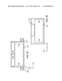
[0017] FIGS. 7A and 7B (SHEET 8 of 8 SHEETS) depict front views of embodiments of the apparatus of any one of FIGS. 1A and 1B.
[0018] The drawings are not necessarily to scale and may be illustrated by phantom lines, diagrammatic representations and fragmentary views. In certain instances, details unnecessary for an understanding of the embodiments (and/or details that render other details difficult to perceive) may have been omitted.
[0019] Corresponding reference characters indicate corresponding components throughout the several figures of the drawings. Elements in the several figures are illustrated for simplicity and clarity and have not been drawn to scale. The dimensions of some of the elements in the figures may be emphasized relative to other elements for facilitating an understanding of the various disclosed embodiments. In addition, common, but well-understood, elements that are useful or necessary in commercially feasible embodiments are often not depicted to provide a less obstructed view of the embodiments of the present disclosure.
LISTING OF REFERENCE NUMERALS USED IN THE DRAWINGS
[0020] 100 apparatus
[0021] 102 pillowcase
[0022] 103 end sections
[0023] 104 pillow pocket
[0024] 106 storage pocket
[0025] 200 first rear pocket
[0026] 201 second rear pocket
[0027] 300 first caddy section
[0028] 301 second caddy section
[0029] 302 first panel section
[0030] 303 second panel section
[0031] 304 first connector
[0032] 305 second connector
[0033] 306 first coupler
[0034] 307 second coupler
[0035] 308 first caddy pocket
[0036] 309 second caddy pocket
[0037] 310 first auxiliary caddy pocket
[0038] 311 second auxiliary caddy pocket
[0039] 312 stitching line
[0040] 314 frontally-positioned pocket
[0041] 900 pillow
[0042] 902 storable object
[0043] 904 user
[0044] 906 bed
[0045] 908 headboard
DETAILED DESCRIPTION OF THE NON-LIMITING EMBODIMENT(S)
[0046] The following detailed description is merely exemplary and is not intended to limit the described embodiments or the application and uses of the described embodiments. As used, the word "exemplary" or "illustrative" means "serving as an example, instance, or illustration." Any implementation described as "exemplary" or "illustrative" is not necessarily to be construed as preferred or advantageous over other implementations. All of the implementations described below are exemplary implementations provided to enable persons skilled in the art to make or use the embodiments of the disclosure and are not intended to limit the scope of the disclosure. The scope of the invention is defined by the claims. For the description, the terms "upper," "lower," "left," "rear," "right," "front," "vertical," "horizontal," and derivatives thereof shall relate to the examples as oriented in the drawings. There is no intention to be bound by any expressed or implied theory in the preceding Technical Field, Background, Summary or the following detailed description. It is also to be understood that the devices and processes illustrated in the attached drawings, and described in the following specification, are exemplary embodiments (examples), aspects and/or concepts defined in the appended claims. Hence, dimensions and other physical characteristics relating to the embodiments disclosed are not to be considered as limiting, unless the claims expressly state otherwise. It is understood that the phrase "at least one" is equivalent to "a". The aspects (examples, alterations, modifications, options, variations, embodiments and any equivalent thereof) are described regarding the drawings. It should be understood that the invention is limited to the subject matter provided by the claims, and that the invention is not limited to the particular aspects depicted and described.
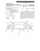
[0047] FIGS. 1A and 1B depict perspective views of embodiments of an apparatus 100 for a pillow 900.
[0048] It will be appreciated that the apparatus 100 does not include the pillow 900 and does not include a storable object 902 (such as a cell phone). The pillow 900 may include any type of pillow purchased at a department store, such as a bed pillow, etc. The storable object 902 may include any type of storable object that is smaller than the size of the pillow 900, such as a cell phone, a magazine, etc. The pillow 900 may include a bed pillow or any type of pillow (such as of the decorative pillow or accent pillow type used in a living room).
[0049] In accordance with all of the embodiments as depicted in all of the FIGS., the apparatus 100 includes (and is not limited to) a pillowcase 102. The pillowcase 102 provides (or more specifically, defines) a minimal combination of a pillow pocket 104 and a storage pocket 106. It will be appreciated that embodiments of the apparatus 100 may include more than the minimal combination of the pillow pocket 104 and the storage pocket 106.
[0050] Preferably, the pillowcase 102 includes two elongated fabric panels attached along a peripheral length of the elongated fabric panels, with one side open for access to the interior of the pillowcase 102 (so that the pillow 900 may be inserted therein and removed therefrom).
[0051] The pillow pocket 104 (that is provided by the pillowcase 102) is configured to receive, at least in part, the pillow 900. The storage pocket 106 (that is provided by the pillowcase 102) is spaced apart from and is isolated from the pillow pocket 104. The storage pocket 106 is configured to receive, at least in part, the storable object 902.
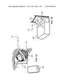
[0052] In accordance with the embodiment as depicted in FIG. 1A, the apparatus 100 is depicted as receiving the pillow 900. A user 904 rests with his head on the apparatus 100.
[0053] In accordance with the embodiment as depicted in FIG. 1B, the apparatus 100 is placed on a bed 906 having a headboard 908. The pillow of FIG. 1A is received in the apparatus 100 of FIG. 1B, and the apparatus 100 is positioned proximate to the headboard 908.
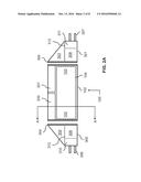
[0054] FIGS. 2A and 2B depict front views of embodiments of the apparatus 100 of any one of FIGS. 1A and 1B. FIG. 2A depicts the apparatus 100 in a disassembled state. FIG. 2B depicts the apparatus 100 in an assembled state.
[0055] In accordance with the embodiment as depicted in FIGS. 2A and 2B (as well as with the embodiments depicted in FIGS. 4, 5 and 6), the apparatus 100 is for the pillow 900 (depicted in FIG. 1A). The apparatus 100 includes (and is not limited to) a synergistic combination of a pillowcase 102, a first caddy section 300, and a second caddy section 301.
[0056] The pillowcase 102 presents end sections 103. The end sections 103 are positioned opposite from each other at the opposite sides (opposite end sections or opposite ends) of the pillowcase 102. The head of the user is to rest between the end sections 103 of the pillowcase 102. The definition of presents includes provides or defines (and any equivalent thereof). The end sections 103 may be called opposite end portions or opposite end sections. The pillowcase 102 may have a rectangular shape (or any desired shape). The pillowcase 102 provides (defines) a pillow pocket 104 configured to receive, at least in part, the pillow 900. The pillow pocket 104 extends between the end sections 103.
[0057] The first caddy section 300 provides (defines) a first caddy pocket 308. The second caddy section 301 provides (defines) a second caddy pocket 309. The first caddy section 300 and the second caddy section 301 extend from the end sections 103 of the pillowcase 102. This is done in such a way that the pillow 900, once received in the pillowcase 102, is positioned and extended between the first caddy section 300 and the second caddy section 301. By way of example, the first caddy pocket 308 and the second caddy pocket 309 are configured to receive and to hold the storable object 902 (depicted in FIG. 1A), such as a cell phone, a tablet computer, etc.
[0058] The first caddy pocket 308 and the second caddy pocket 309 help the user to organize the placement (storage) of devices, such as a tablet computer, a remote control device for a television or other apparatus, a book, a bottle, baby essentials for mothers with babies, a medication container, a medical device for patients or seniors, etc. The first caddy pocket 308 and the second caddy pocket 309 help to reduce (preferably eliminate) clutter in a room.
[0059] In accordance with an embodiment (as depicted in FIGS. 2A and 2B), the pillowcase 102 is configured or further adapted to provide (define) a first rear pocket 200 and/or a second rear pocket 201 that are positioned at a rear section of the pillowcase 102. By way of example, the first rear pocket 200 and the second rear pocket 201 are configured to receive and to hold the storable object 902 (depicted in FIG. 1A), such as a cell phone, a tablet computer, a magazine, a diary, etc.
[0060] In accordance with an embodiment (as depicted in FIGS. 2A and 2B), the first caddy section 300 and the second caddy section 301 are removably detachable from respective end sections 103 of the pillowcase 102. The first caddy section 300 includes a first connector 304 configured to connect the first caddy section 300 to a respective end section 103 of the pillowcase 102. The second caddy section 301 includes a second connector 305 configured to connect the second caddy section 301 to a respective end section 103 of the pillowcase 102.
[0061] The first caddy section 300 includes the first connector 304 having (for instance) a touch fastener, also called a VELCRO (TRADEMARK) fastener, in which a portion of the touch fastener is positioned along one side of the first caddy section 300, and a corresponding portion of the touch fastener is attached to the end section 103 of the pillowcase 102. The second connector 305 includes the touch fastener, in which a portion of the touch fastener is positioned along one side of the second caddy section 301, and a corresponding portion of the touch fastener is attached to the end section 103 of the pillowcase 102. FIG. 2A depicts the first caddy section 300 detached from the pillowcase 102, and the second caddy section 301 detached from the pillowcase 102. FIG. 2B depicts the first caddy section 300 attached to the pillowcase 102, and the second caddy section 301 attached to the pillowcase 102.
[0062] In accordance with an embodiment (as depicted in FIGS. 2A and 2B), the first caddy section 300 includes a first panel section 302 (also called a web) extending between a respective end section 103 of the pillowcase 102 and the first caddy pocket 308 of the first caddy section 300. In addition, the second caddy section 301 includes a second panel section 303 (also called a web) extending between a respective end section 103 of the pillowcase 102 and the second caddy pocket 309 of the second caddy section 301.
[0063] In accordance with an embodiment (as depicted in FIGS. 2A and 2B), the first caddy section 300 includes a first coupler 306 (also called a strap) configured to attach the first caddy section 300 to the headboard 908 (depicted in FIG. 1B) of the bed 906. In addition, the second caddy section 301 includes a second coupler 307 (also called a strap) configured to attach the second caddy section 301 to the headboard 908 (depicted in FIG. 1B) of the bed 906. In this arrangement, the pillow 900 may be held in a fixed position relative to the bed 906. For instance, the first coupler 306 and the second coupler 307 may include a clip assembly (known and not depicted). The first coupler 306 and the second coupler 307 may be configured to be length adjustable (configured to adjust connection with a stationary bed component, such as the bed frame or bed post, of the bed 906). In this manner, it may be possible to fill in the space between the headboard 908 and the mattresses (if so desired). In addition, the first coupler 306 and the second coupler 307 are configured to facilitate an amount of height adjustment of the pillowcase 102 (up and down motion), if so desired. The first coupler 306 and the second coupler 307 may be called a restraint, an isolation strap or a strap.
[0064] In accordance with an embodiment (as depicted in FIGS. 2A and 2B), the first caddy section 300 further includes a first auxiliary caddy pocket 310 positioned relative to the first caddy pocket 308. In addition, the second caddy section 301 further includes a second auxiliary caddy pocket 311 positioned relative to the second caddy pocket 309.
[0065] By way of example, a stitching line 312 is used to form the first caddy pocket 308, the second caddy pocket 309, the first auxiliary caddy pocket 310 and the second auxiliary caddy pocket 311.
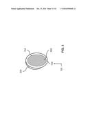
[0066] FIG. 3 depicts a cross-sectional view of an embodiment of the apparatus 100 of FIG. 2A. FIG. 3 depicts a cross-sectional side view of the apparatus 100 through the line A-A of FIG. 2A. FIG. 3 depicts an embodiment of the first rear pocket 200 of FIG. 2A. The first rear pocket 200 and/or the second rear pocket 201 extend(s) downwardly from a top section of the pillowcase 102. Preferably, the first rear pocket 200 and the second rear pocket 201 extend down by about 75 present toward the bottom section of the pillowcase 102 (thereby giving ample room for storage of articles).
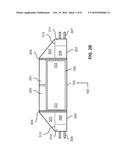
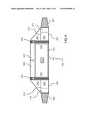
[0067] FIG. 4 depicts a front view of an embodiment of the apparatus 100 of any one of FIGS. 1A and 1B.
[0068] In accordance with the embodiment as depicted in FIG. 4, the first caddy section 300 includes the first connector 304 in which the first connector 304 includes a zipper. In addition, the second caddy section 301 includes the second connector 305 in which the second connector 305 includes a zipper. The pillowcase 102 also includes respective zippers positioned and affixed to the opposite end sections 103 (opposite end sections) of the pillow 900. In this manner, the first caddy section 300 and the second caddy section 301 may be removably connectable to the pillowcase 102 (by using zippers). The zipper (also called a zip, a fly, a zip fastener, a clasp locker, etc.) includes interlockable teeth, and is a device for binding the edges of an opening of fabric or other flexible material.
[0069] In accordance with the embodiment as depicted in FIG. 4, the first caddy section 300 includes the first coupler 306 in which the first coupler 306 includes an elastic band (an elastically deformable band). In addition, the second caddy section 301 includes the second coupler 307 in which the second coupler 307 includes an elastic band (an elastically deformable band).
[0070] In accordance with the embodiment as depicted in FIG. 4, the pillowcase 102 provides (defines) a frontally-positioned pocket 314 that is positioned centrally between the opposite sides (opposite end sections) of the pillowcase 102 on the opposite side from the first rear pocket 200 and/or the second rear pocket 201. In this manner, two people can lay their heads on the pillowcase 102 on each side of the frontally-positioned pocket 314 (if so desired).
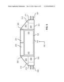
[0071] FIG. 5 depicts a front view of an embodiment of the apparatus 100 of any one of FIGS. 1A and 1B.
[0072] In accordance with the embodiment as depicted in FIG. 5, the first caddy section 300 and the second caddy section 301 are fixedly attached to the respective end sections 103 of the pillowcase 102. For instance, the first caddy section 300 includes the first connector 304 in which the first connector 304 includes stitching. In addition, the second caddy section 301 includes the second connector 305 in which the second connector 305 includes stitching. For this embodiment, the touch fastener is not used (deployed).
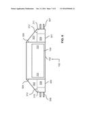
[0073] FIG. 6 depicts a front view of an embodiment of the apparatus 100 of any one of FIGS. 1A and 1B.
[0074] In accordance with the embodiment as depicted in FIG. 6, the first rear pocket 200 and the second rear pocket 201 are not provided.
[0075] FIGS. 7A and 7B depict front views of embodiments of the apparatus 100 of any one of FIGS. 1A and 1B.
[0076] In accordance with the embodiments as depicted in FIGS. 7A and 7B, the first caddy section 300 and the second caddy section 301 are not provided.
[0077] This written description uses examples to disclose the invention, including the best mode, and also to enable any person skilled in the art to make and use the invention. The patentable scope of the invention is defined by the claims, and may include other examples that occur to those skilled in the art. Such other examples are within the scope of the claims if they have structural elements that do not differ from the literal language of the claims, or if they include equivalent structural elements with insubstantial differences from the literal language of the claims.
[0078] It may be appreciated that the assemblies and modules described above may be connected with each other as required to perform desired functions and tasks within the scope of persons of skill in the art to make such combinations and permutations without having to describe each and every one in explicit terms. There is no particular assembly or component that may be superior to any of the equivalents available to the person skilled in the art. There is no particular mode of practicing the disclosed subject matter that is superior to others, so long as the functions may be performed. It is believed that all the crucial aspects of the disclosed subject matter have been provided in this document. It is understood that the scope of the present invention is limited to the scope provided by the independent claim(s), and it is also understood that the scope of the present invention is not limited to: (i) the dependent claims, (ii) the detailed description of the non-limiting embodiments, (iii) the summary, (iv) the abstract, and/or (v) the description provided outside of this document (that is, outside of the instant application as filed, as prosecuted, and/or as granted). It is understood, for this document, that the phrase "includes" is equivalent to the word "comprising." The foregoing has outlined the non-limiting embodiments (examples). The description is made for particular non-limiting embodiments (examples). It is understood that the non-limiting embodiments are merely illustrative as examples.
User Contributions:
Comment about this patent or add new information about this topic:
Images included with this patent application:
 |  |
 |  |
 |  |
 |  |
 |
| Similar patent applications: | |
| Date | Title |
|---|---|
| 2016-10-06 | Liquid crystal module and curved surface display device |
| 2016-10-06 | Medical monitor, electronic apparatus, and video display unit |
| 2016-10-06 | Optical module and manufacturing method thereof |
| 2016-10-06 | Stage apparatus and microscope |
| 2016-10-06 | Liquid crystal display and manufacturing method thereof |
| New patent applications in this class: | |
| Date | Title |
|---|---|
| 2022-09-22 | Electronic device |
| 2022-09-22 | Front-facing proximity detection using capacitive sensor |
| 2022-09-22 | Touch-control panel and touch-control display apparatus |
| 2022-09-22 | Sensing circuit with signal compensation |
| 2022-09-22 | Reduced-size interfaces for managing alerts |