Patent application title: Packaging Machine
Inventors:
Masaaki Takahashi (Aichi, JP)
Shinji Ishikawa (Aichi, JP)
Masanori Toyoyoshi (Aichi, JP)
Assignees:
General Packer Co., Ltd.
IPC8 Class: AB65B5102FI
USPC Class:
532847
Class name: Package making means to fill and close preformed receptacle receptacle comprising bag
Publication date: 2016-05-05
Patent application number: 20160122057
Abstract:
A packaging machine includes a pair of grips holding vicinities of two
sides of a bag mouth of a packaging bag, a moving body to intermittently
moving the paired grips every one of a plurality of packaging steps, and
a paper packaging bag sealing device provided in a section where a
sealing step is carried out, for sealing a paper packaging bag to which a
sealing adhesive agent has been applied.Claims:
1. A packaging machine comprising: a pair of grips holding vicinities of
two sides of a bag mouth of a packaging bag; a moving body to
intermittently moving the paired grips every one of a plurality of
packaging steps; and a paper packaging bag sealing device provided in a
section where a sealing step is carried out, for sealing a paper
packaging bag to which a sealing adhesive agent has been applied.
2. The packaging machine according to claim 1, further comprising a resin packaging bag sealing device provided in the section where the sealing step is carried out, for sealing a resin packaging bag and a reciprocating member which reciprocates the paper packaging bag sealing device or the resin packaging bag sealing device.
3. The packaging machine according to claim 1, wherein the paper packaging bag sealing device includes a heater melting the sealing adhesive agent of the paper packaging bag.
4. The packaging machine according to claim 3, wherein the heater has a hot air supply block disposed near the first fold guide.
5. The packaging machine according to claim 1, wherein the paper packaging bag sealing device includes a fold guide folding a vicinity of the bag mouth of the paper packaging bag along a widthwise direction.
6. The packaging machine according to claim 5, wherein the fold guide includes a first fold guide folding a folded part of the paper packaging bag in a direction substantially perpendicular to a lengthwise direction and a second fold guide folding the folded part folded by the first fold guide in the direction substantially perpendicular to the lengthwise direction, in a direction horizontal to the lengthwise direction.
7. The packaging machine according to claim 1, further comprising a pair of clamping parts provided in a section where a sealing step is carried out, the clamping parts clamping the paper packaging bag from a surface and a back thereof respectively thereby to form a fold line, wherein one of the clamping parts has a fold line forming protrusion and the other clamping part has a fold line forming recessed streak brought into mesh engagement with the protrusion.
8. The packaging machine according to claim 1, wherein the paper packaging bag sealing device has a pair of clamping bodies configured to clamp the paper packaging bag from a surface and a back thereof respectively thereby to press the surface and the back of the paper packaging bag against each other.
9. The packaging machine according to claim 8, wherein the paired clamping bodies comprise a pair of pressing rollers.
10. The packaging machine according to claim 1, wherein a step of sealing the paper packaging bag includes a step of forming a fold line on the paper packaging bag, a step of melting the sealing adhesive agent for the paper packaging bag, a step of widthwise folding a vicinity of the bag mouth of the paper packaging bag and a step of clamping the paper packaging bag from a surface and a back thereof, thereby pressure bonding the paper packaging bag.
Description:
CROSS-REFERENCE TO RELATED APPLICATIONS
[0001] This application is based upon and claims the benefit of priority from the prior Japanese Patent Application No. 2014-220170 filed on Oct. 29, 2014, the entire contents of which are incorporated herein by reference.
BACKGROUND
[0002] 1. Technical Field
[0003] The present disclosure relates to a packaging machine which fills a packaging bag with an article and seals the packaging bag, and more particularly to a packaging machine which can seal a paper packaging bag without occurrence of inclined seal in sealing the paper packaging bag.
[0004] 2. Related Art
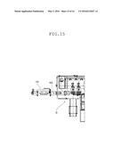
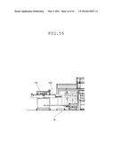
[0005] In filling a paper packaging bag with an article and then sealing the paper packaging bag, the paper packaging bag is filled with the article and thereafter, the paper packaging bag is carried out of a packaging machine Q by a conveyor 100 as shown in FIGS. 15 and 16. The paper packaging bag is then sealed by a paper packaging bag sealing machine 110 installed in a post-process line.
[0006] However, the paper packaging bag filled with the article is just placed on the conveyor 100 and is not held at portions thereof near a sealed part in sealing the paper packaging bag. This sometimes results in occurrence of inclined seal depending upon a state of the paper packaging bag.
SUMMARY
[0007] Therefore, an object of the present disclosure is to provide a packaging machine which can seal the paper packaging bag therein without occurrence of inclined seal in sealing the paper packaging bag.
[0008] The disclosure provides a packaging machine including a pair of grips holding vicinities of two sides of a bag mouth of a packaging bag, a moving body to intermittently moving the paired grips every one of a plurality of packaging steps, and a paper packaging bag sealing device provided in a section where a sealing step is carried out, for sealing a paper packaging bag to which a sealing adhesive agent has been applied.
[0009] According to the above-described construction, the vicinities of the sides of the bag mouth of the paper packing bag are held by the paired grips. Accordingly, the paper packaging bag can be sealed within the packaging machine without occurrence of the inclined seal in sealing.
[0010] The packaging machine may further include a resin packaging bag sealing device provided in the section where the sealing step is carried out, for sealing a resin packaging bag and a reciprocating member which reciprocates the paper packaging bag sealing device or the resin packaging bag sealing device. According to this construction, both the resin packaging bag and the paper packaging bag can be sealed by changing sealing devices.
BRIEF DESCRIPTION OF THE DRAWINGS
[0011] In the accompanying drawings:
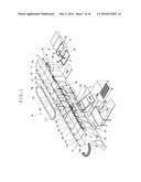
[0012] FIG. 1 is a schematic perspective view of a packaging machine according to one embodiment;
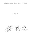
[0013] FIG. 2 is an illustration diagram of the packaging machine in a packaging step;
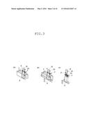
[0014] FIG. 3 is also an illustration diagram of the packaging machine in the packaging step;
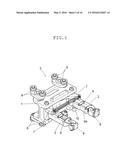
[0015] FIG. 4 is further an illustration diagram of the packaging machine in the packaging step;
[0016] FIG. 5 is a perspective view of a moving body;
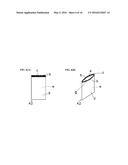
[0017] FIGS. 6A and 6B are a front view of a paper packaging bag and a perspective view of the paper packaging bag respectively;
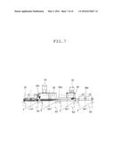
[0018] FIG. 7 is a schematic front view of the packaging machine, showing a paper packaging bag sealing step;
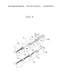
[0019] FIG. 8 is a schematic perspective view of the packaging machine, showing the paper packaging bag sealing step;
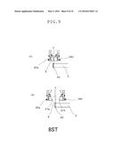
[0020] FIG. 9 is a schematic right side view of the packaging machine, showing an eighth process;
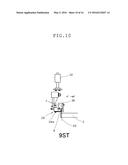
[0021] FIG. 10 is a schematic right side view of the packaging machine, showing a ninth process;
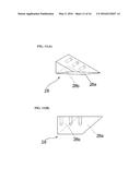
[0022] FIGS. 11A and 11B are a perspective view and a plan view of a first folding guide of the packaging machine respectively;
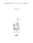
[0023] FIG. 12 is a schematic right side view of the packaging machine, showing a tenth process;
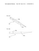
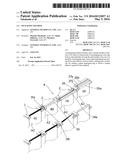
[0024] FIGS. 13A and 13B are a perspective view and a plan view of a second folding guide of the packaging machine respectively;
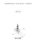
[0025] FIG. 14 is a schematic right side view of a clamping member of the packaging machine, showing the working of the clamping member;
[0026] FIG. 15 is a partial plan view of a conventional packaging machine; and
[0027] FIG. 16 is a partial front view of the conventional packaging machine.
DETAILED DESCRIPTION
[0028] According to one embodiment, a packaging machine includes a pair of grips 2 holding vicinities of two opposite parts of a bag mouth a of a paper packaging bag A2, a moving body 3 configured to intermittently move the paired grips 2 in every one of a plurality of packaging steps, and a paper packaging bag sealer 4 configured to seal the paper packaging bag including a part in which a sealing step is to be carried out and to which a sealing adhesive b has been applied, whereby the paper packaging bag can be sealed in the machine without an occurrence of inclined seal.
[0029] An embodiment will be described with reference to FIGS. 1 to 13. A packaging machine P of the embodiment includes a pair of grips 2 holding vicinities of two opposite parts of a bag mouth a of a paper packaging bag A2, a moving body 3 configured to intermittently move the paired grips 2 in every one of a plurality of packaging steps, and a paper packaging bag sealer 4 configured to seal the paper packaging bag A2 including a part in which a sealing step is to be carried out and to which a sealing adhesive b has been applied, whereby the paper packaging bag A2 can be sealed in the machine without an occurrence of inclined seal. The paired grips 2, the mobbing body 3 and the paper packaging bag sealer 4 will be described in detail in the following.
[0030] The packaging machine P of the embodiment is configured to fill a gusset bag with an article such as pet food and then seal the gusset bag. The gusset bag is formed with a zipper f (see FIG. 2B) near a bag mouth a. The gusset bag may be a large bag having a length of 600 to 1050 mm, a width of 300 to 50 mm and a thickness of 50 to 80 mm. The article should not be limited to the pet food but may include a granular material such as rice or fertilizer or a powdery material such as wheat flour.
[0031] In the packaging machine P, a number of moving bodies 3 (see FIG. 5) are horizontally moved along an annular passage 5 including two linear sections 5a and 5b and two semicircular sections 5c and 5d located at opposite ends of the linear sections 5a and 5b respectively, as shown in FIG. 1. More specifically, the moving bodies 3 are intermittently moved in every one of packaging steps (1) to (12) so that a packaging bag A supported by a pair of grips 2 in a suspended manner with a bag mouth a up is filled with an article and then sealed. All the steps (1) to (12) from a step of supplying bags A to a step of discharging products out of the packaging machine are arranged at one 5b of the linear sections constituting the annular passage 5.
[0032] The paired grips 2 are configured to hold vicinities of two opposite parts of a bag mouth a of a paper packaging bag A2 and are mounted on the moving body 3 to be intermittently moved with the moving body 3 in every packaging step, as shown in FIG. 5. More specifically, the moving body 3 includes a base 1 on which a plurality of sets of rollers 6 is rotatably mounted. The rollers 6 are attached to rails (not shown) forming the annular passage 5. The base 1 is mounted to an annular conveyor belt (not shown) driven by a known intermittent drive unit (not shown) including an indexing mechanism and an electric motor.
[0033] A pair of right and left holders 7 are pivotally mounted on the base 1 of the moving body 3 as shown in FIG. 5. The paired grips 2 are mounted on the holders 7 respectively. Rollers 10 are fixed to operating rods 9a of link mechanisms 9 respectively.
[0034] The rollers 10 are rotated by moving pressing members (not shown) forward and backward by a cam mechanism (not shown) which is controlled by a known drive unit, so that packaging bag clamping parts 8 of the grips 2 are opened and closed, respectively.
[0035] The packaging bag A includes a resin-made packaging bag A1 and a paper-made packaging bag A2. The packaging machine P is configured to fill either the resin-made packaging bag A1 or the paper-made packaging bag A2 with the article and then seal the bag within the machine. When the resin-made packaging bag A1 is filled with the article by the packaging machine P, the article (pet food) is packaged through a bag feeding step (1), a printing/printing quality inspecting step (2), an unzipping and one-side grip checking step (3), a bag opening/inflating step (4), a filling step (5), a vibrating/gas filling step (6) and (7), a deaeration/temporarily sealing step (8), a first sealing and outside discharging step (9), a second sealing step (10), a cooling/discharging step (11) and a product discharging step (12), as shown in FIGS. 2 to 4.
[0036] More specifically, the packaging bag A (the resin-made packaging bag A1, in this case) is supplied to the paired grips 2 in the bag feeding step (1). The bag feeding step (1) includes a step of separating one of packaging bags A loaded on a bag magazine 11 by a separating mechanism including suction discs 12, a step of holding the separated packaging bag A by a horizontal transfer unit and transferring the separated packaging bag to a bag placing section 13, a step of correcting a position of the packaging bag A transferred to the bag placing section 13, a step of transferring to a holding unit 15 the packaging bag A held by a pivot arm provided with suckers 14 and a step of transferring the packing bag A from the holding unit 15 to the paired grips 2 after execution of height calibration of the packaging bag A during transfer to the paired grips 2.
[0037] In the printing/printing quality inspecting step (2), an expiration date and the like are printed on the packaging bag A by an ink jet printer (IJP) and a printing quality inspection is carried out by a printing quality inspecting camera. In the chuck opening and one-side grip checking step (3), the chuck f is opened, and it is checked whether or not the paired grips 2 has occurred one-side grip. The chuck f near the mouth a of the packaging bag A is opened by a claw 16 as shown in FIG. 2B. Further, one or more packaging bags which have failed in printing or which contain printing failure such as character missing have been excluded from the packaging machine at this step.
[0038] In the opening/inflating step (4), the mouth a of the packaging bag A is opened so that the packaging bag A is inflated. An upper end and a lower end of the packaging bag A are adsorbed to suckers 17 with the result that the packaging bag A is expanded, as shown in FIG. 2C. In the filling step (5), the packaging bag A is filled with pet food. A movable funnel 18 is inserted through the mouth a of the packaging bag A suspended by the paired grips 2, so that pet food is supplied through the movable funnel 18 and a fixed funnel 19 (see FIG. 1) into the packaging bag A, as shown in FIG. 2D. The packaging bag A is simultaneously shaped.
[0039] In the vibrating/gas filling step (6) and (7), the packaging bag A filled with the pet food is vibrated to be shaped and is filled with nitrogen. A nitrogen gas is supplied from a gas filling nozzle 20 into the packaging bag A and the packaging bag A is shaped, as shown in FIG. 2E. In the deaeration/temporarily sealing step (8), the packaging bag A is deaerated and a part of the packaging bag A located near the bag mouth a is temporarily sealed. A deaerating nozzle 21 is inserted through the bag mouth a into the packaging bag A so that extra air is removed from the packaging bag A, as shown in FIG. 2F. Thereafter, the part of the packaging bag A located near the bag mouth a is clamped by a temporal sealing device to be temporarily sealed.
[0040] In the first sealing and outside discharging step (9), a first seal is applied to the part of the packaging bag A located near the bag mouth a by a first sealing device 23 as shown in FIG. 2G. Further, one or more packaging bags which fail to be opened and inflated are not filled with pet food and in which metal bodies are found, and the like are discharged outside the system. In the second sealing step (10), a second seal is applied to the part of the packaging bag A located near the bag mouth a. The part of the packaging bag A located near the bag mouth a is heat-sealed by a second sealing device 24 as shown in FIG. 2H.
[0041] In the cooling/outside discharging step (11), a sealed part is cooled and one or more packaging bags defective in seal and the like are discharged outside the system. The sealed part near the bag mouth a is cooled by a cooling bar 25 as shown in FIG. 2I. Further, in the product discharging step (12), the packaging bag S filled with the article (pet food) and sealed is discharged outside the packaging machine.
[0042] On the other hand, when the paper packaging bag A2 is filled with an article to be packaged by the packaging machine P, the packaging machine P performs the bag feeding step (1), the printing/printing quality inspecting step (2), the unzipping and one-side grip checking step (3), the bag opening/inflating step (4), the filling step (5), the vibrating/gas filling step (6) and (7) and the product discharging step (12) in the same manner as described above. However, the case of filling the paper packaging bag A2 differs in the eighth to eleventh steps (8) to (11) from the case of filling the packaging bag A.
[0043] The following will describe the eighth to eleventh steps and the construction of the packaging machine P relating to the eighth to eleventh steps. The paper packaging bag A2 used to package the article in the embodiment is formed so that a back side packaging paper e is longer than a surface side packaging paper d by the length (the height) of a folded part c. A sealing adhesive agent b is applied to both an inner surface of the folded part c and a part of packaging bag A2 against which the 180-degree folded part c abuts.
[0044] When the paper packaging bag A2 is filled with the article and sealed by the packaging machine P, the eighth to eleventh steps are a seal step in which are carried out a step of forming a fold line on the paper packaging bag A2, a step of melting the sealing adhesive agent b for the paper packaging bag A2, a step of widthwise folding the vicinity of the bag mouth a of the paper packaging bag A2 and a step of clamping the paper packaging bag A2 from surface and back sides thereby pressure bonding the paper packaging bag A2. The paper packaging bag A2 can reliably be sealed through these steps.
[0045] A pair of clamping parts 26a and 26b are provided in a section where the eighth step (8) is carried out, for the purpose of clamping the paper packaging bag A2 from surface and back sides thereby to form the fold line g, as shown in FIG. 9. One of the clamping parts 26a and 26b has a fold line forming protrusion 27a, and the other clamping member 26b or 26a has a fold line forming recessed streak 27b which is brought into mesh engagement with the protrusion 27a.
[0046] The fold line g is formed widthwise with respect to the paper packaging bag A2 so as to cross a lower side of the folded part c of the back side packaging paper e. Accordingly, the paired clamping parts 26a and 26b are held by the paired grips 2 to be moved to the section where the eighth step (8) is carried out to be located so that the fold line g is formed on the lower side of the folded part c of the back sided packaging paper e, as shown in FIG. 9B. The fold line g is thus formed by causing the clamping parts 26a and 26b to come close to the surface and back sides of the paper packaging bag A2 respectively and clamping the paper packaging bag A2, so that the fold line g is formed. This can fold the folded part c easily and reliably with the result that the paper packaging bag A2 can reliably be sealed.
[0047] A paper packaging bag sealing device 4 is provided in a section where the ninth to eleventh steps (9) to (11) are carried out, for the purpose of sealing the paper packaging bag A2 to which the sealing adhesive agent b has been applied, as shown in FIG. 7 or 8. The sealing device 4 is disposed within the packaging machine P to seal the paper packaging bag A2 with both ends near the bag mouth a being held by the paired grips 2, so that the paper packaging bag A2 can be sealed without occurrence of an inclined seal in sealing the paper packaging bag A2.
[0048] The paper packaging bag sealing device 4 includes a first fold guide 28, a heater 29, a second fold guide 30 and a pair of clamping bodies 31. The fold guide 28 is provided near the upstream of a section where the ninth step (9) is carried out, as shown in FIG. 7 or 8. The fold guide 28 is configured to fold the folded part c along the fold line g in a direction substantially perpendicular to the lengthwise direction of the paper packaging bag A2. More specifically, the fold guide 28 is formed into a block body provided with an inclined surface 28a as shown in FIGS. 11A and 11B. When moved to the section where the ninth step (9) is carried out, the paper packaging bag A2 held by the paired grips 2 is brought into contact with the inclined surface 28a thereby to be gradually folded 90 degrees along the fold line g by an underside 28b.
[0049] Further, the heater 29 is provided in the section where the ninth step (9) is carried out, for the purpose of melting the sealing adhesive agent b of the paper packaging bag A2 as shown in FIG. 10. The heater 29 has a 29a which is disposed along a movement direction of the paper packaging bag A2 held by the paired grips 2 so as to be located below the first fold guide 28. As a result, hot air is blown from the hot air supply block 29a against the folded part c and the surface side packaging paper d to both of which the adhesive agent b is applied, with the paper packaging bag A2 being folded 90 degrees by the first fold guide 28, so that the adhesive agent can be melted immediately before sealing, with the result that the paper packaging bag A2 can reliably be sealed.
[0050] The second fold guide 30 is provided in the section where the tenth step (10) is carried out, as shown in FIG. 7 or 8. The second fold guide 30 is configured to fold the folded part 6 of the paper packaging bag A2 along fold line g in the horizontal direction relative to the lengthwise direction. More specifically, the second fold guide 30 is formed into a block body provided with an inclined surface 30a as shown in FIGS. 13A and 13B. When moved to the section where the tenth step (10 is carried out, the paper packaging bag A2 held by the paired grips 2 is brought into contact with the inclined surface 30a thereby to be gradually folded 90 degrees (180 degrees in total) along the fold line g by a side surface 30b.
[0051] Thus, the paper packaging bag sealing device 4 has the fold guide (the first and second fold guides 28 and 30) folding the vicinity of the bag mouth a of the paper packaging bag A2 along the widthwise direction. Accordingly, the paper packaging bag A2 can more reliably be sealed by being folded. Further, since the paper packaging bag sealing device 4 has the first and second fold guides 28 and 30, the paper packaging bag A2 can more reliably be sealed by being folded in a stepwise manner.
[0052] A pair of clamping bodies 31a and 31b are provided between the sections where the tenth and eleventh steps (10) and (11) are carried out, as shown in FIG. 7, 8 or 14. The clamping bodies 31a and 31b are provided for clamping the paper packaging bag A2 from the surface and back sides thereof thereby to press the surface and back sides against each other. The paper packaging bag A2 can more reliably be sealed by clamping the paper packaging bag A2 from the surface and back sides thereof thereby to press the surface and back sides against each other.
[0053] It is desirable that the clamping bodies 31a and 31b comprise a pair of pressing rollers as in the embodiment. When the pressing rollers are rotated in synchronization with the movement of the paper packaging bag A2 held by the paired grips 2, the paper packaging bag A2 can reliably be sealed with prevention of failure in sealing. Further, the pressing rollers are configured to be reciprocable to cope with pressing the paper packaging bags A2 having different thicknesses by changing the pressure therebetween by an electro pneumatic regulator (not shown).
[0054] Further, the paper packaging bag sealing device 4 (the first fold guide 28, the heater 29, the second fold guide 30 and the paired clamping bodies 31a and 31b) of the packaging machine P includes reciprocating members 32 and 33 and is configured to be reciprocable. More specifically, the first fold guide 28 and the heater 29 are configured to be moved in an up-down direction by the reciprocating member 32 (a cylinder) provided over the first fold guide 28 and the heater 29, as shown in FIG. 7 or 10. When the paper packaging bag A2 is packaged, the first fold guide 28 and the heater 29 are descended by the reciprocating member 32 (the cylinder) so that the folding step and the adhesive agent b melting step can be carried out.
[0055] Further, the second fold guide 30 and the paired clamping parts 31a and 31b are configured to be moved in the up-down direction by the reciprocating member 33 (a cylinder) provided over the second fold guide 30 and the paired clamping parts 31a and 31b, as shown in FIG. 7 or 12. When the paper packaging bag A2 is packaged, the second fold guide 30 and the paired clamping parts 31a and 31b are descended by the reciprocating member 33 (the cylinder) so that the folding step and the adhesive agent b melting step can be carried out.
[0056] On the other hand, when the resin packaging bag A1 is packaged, the paper packaging bag sealing device 4 is ascended by the reciprocating members 32 and 33, and the sealing step is carried out by a resin packaging bag sealing device (the first sealing device 23 and the second sealing device 24) which seals the resin packaging bag A1. Thus, the packaging machine P is configured to seal both the resin and paper packaging bags A1 and A2 by changing the sealing device within the machine.
[0057] In the packaging machine P of the foregoing embodiment, the paper packaging bag sealing device 4 includes the first fold guide 28, the heater 29, the second fold guide 30 and the paired clamping bodies 31a and 31b. However, the paper packaging bag sealing device may include the clamping parts forming the fold line, and the clamping parts may be reciprocated by the reciprocating member. Further, the paper packaging bag sealing device may further comprise another means for sealing the paper packaging bag. Still further, although the paper packaging bag sealing device 4 of the packaging machine P is reciprocable by the reciprocating members 32 and 33 in the foregoing embodiment, the resin packaging bag sealing device may be reciprocable by the reciprocating members or both the paper packaging bag sealing device and the resin packaging bag sealing device may be reciprocable by the reciprocating members.
[0058] The foregoing description and drawings are merely illustrative of the present disclosure and are not to be construed in a limiting sense. Various changes and modifications will become apparent to those of ordinary skill in the art. All such changes and modifications are seen to fall within the scope of the appended claims.
User Contributions:
Comment about this patent or add new information about this topic:
| People who visited this patent also read: | |
| Patent application number | Title |
|---|---|
| 20200184967 | SPEECH PROCESSING SYSTEM |
| 20200184966 | WAKEWORD DETECTION |
| 20200184965 | COGNITIVE TRIGGERING OF HUMAN INTERACTION STRATEGIES TO FACILITATE COLLABORATION, PRODUCTIVITY, AND LEARNING |
| 20200184964 | SYSTEMS AND METHODS OF OPERATING MEDIA PLAYBACK SYSTEMS HAVING MULTIPLE VOICE ASSISTANT SERVICES |
| 20200184963 | VIRTUAL ASSISTANT AUGMENTATION SYSTEM |
Images included with this patent application:
 |  |
 |  |
 |  |
 |  |
 |  |
 |  |
 |  |
 |  |
 |
| Similar patent applications: | |
| Date | Title |
|---|---|
| 2015-10-22 | Bag-filling machine |
| New patent applications in this class: | |
| Date | Title |
|---|---|
| 2018-01-25 | Zipper closer |
| 2015-12-31 | Protective packaging device queue control |
| 2014-07-03 | Gas charging method and gas charging apparatus for a bag equipped with gas compartment |
| 2013-06-27 | Aseptic filling machine |
| 2010-12-30 | Ice bagging apparatus |
| New patent applications from these inventors: | |
| Date | Title |
|---|---|
| 2014-11-13 | Packaging bag feeder in packaging machine |
| 2014-11-13 | Grip width adjusting mechanism |
| 2014-11-13 | Packaging machine |
| 2014-11-13 | Gas-filliing packaging method and packaging machine therefor |
| Top Inventors for class "Package making" | |
| Rank | Inventor's name |
|---|---|
| 1 | Donald E. Weder |
| 2 | Dennis J. May |
| 3 | Samuel D. Griggs |
| 4 | Patrick R. Lancaster, Iii |
| 5 | Giuseppe Monti |