Patent application title: Sucker Skid
Inventors:
Dalton Wires (Taft, CA, US)
IPC8 Class: AE21B1915FI
USPC Class:
414 2257
Class name: With slope change horizontal to/from vertical guided skate or pusher
Publication date: 2016-04-28
Patent application number: 20160115747
Abstract:
The Sucker Skid of the present invention provides an easy to use tool for
the oil and gas industry to facilitate the process of laying down or
installing sucker rods typically used in an oil well without the need for
a fourth hand. The Sucker Skid has three primary components, a long boom,
front and rear legs of different heights to cause the boom to have an
angle with respect to the ground, and a rolling carriage that can travel
along the boom and is equipped with a cradle sized to receive a sucker
rod.Claims:
1. A Sucker Skid comprising: a boom having at least one frame rail with a
front, a back and a length; a carriage with one or more wheels in rolling
contact on said at least one frame rail wherein said carriage can moved
along said length of said at least one frame rail from said front to said
back and from said back to said front; a cradle sized to receive a sucker
rod and attached to said carriage; and one or more legs connected to said
boom wherein said one or more legs cause said boom to have an angle with
respect to said ground.
2. The Sucker Skid of claim 1 wherein said cradle is rotatably attached to said carriage.
3. The Sucker Skid of claim 1 wherein said cradle has a curved surface.
4. The Sucker Skid of claim 1 wherein said cradle is v-shaped.
5. The Sucker Skid of claim 1 wherein said cradle has a soft material.
6. The Sucker Skid of claim 1 wherein said one or more wheels is four upper wheels and four lower wheels.
7. The Sucker Skid of claim 1 wherein said one or more wheels is four upper wheels and two lower wheels.
8. The Sucker Skid of claim 1 further comprising a stopper system.
9. The Sucker Skid of claim 8 wherein said stopper system has a spring loaded ball partially depressed within said boom.
10. The Sucker Skid of claim 1 wherein said boom further comprises a left frame, a right frame and a middle frame connecting said left frame to said right frame.
11. A Sucker Skid comprising: a boom having a left frame, a right frame and a middle frame each having a top, bottom and length and wherein said middle frame connects said left frame to said right frame to create a boom width; a carriage having a top housing, a right housing, a left housing and an open bottom wherein said open bottom is sized slightly larger than said boom width of said boom of same; a plurality of wheels wherein at least one wheel is mounted on said left housing and in rolling contact with said left frame and at least one wheel is mounted on said right housing and in rolling contact with said right frame; a cradle attached to said carriage and sized to receive a sucker rod; and one or more legs connected to said boom wherein said one or more legs cause said boom to have an angle with respect to said ground.
12. The Sucker Skid of claim 11 wherein said plurality of wheels further comprises: at least one top wheel mounted on said left housing near said top housing and in rolling contact with said top of said left frame of said boom; at least one bottom wheel mounted on said left housing near said open bottom and in rolling contact with said bottom of said left frame of said boom; at least one top wheel mounted on said right housing near said top housing and in rolling contact with said top of said right frame of said boom; and at least one bottom wheel mounted on said right housing near said open bottom and in rolling contact with said bottom of said right frame of said boom.
13. The Sucker Skid of claim 12 wherein said cradle is rotatably attached to said carriage.
14. The Sucker Skid of claim 12 wherein said cradle has a curved surface sized to receive a sucker rod.
15. The Sucker Skid of claim 12 wherein said cradle is v-shaped.
16. The Sucker Skid of claim 12 wherein said cradle has a soft material.
17. The Sucker Skid of claim 12 further comprising a stopper system.
18. A method of laying down a sucker rod comprising the steps of: a. providing a Sucker Skid comprising a boom having at least one frame rail with a front, a back and a length; a carriage configured to move along said length of said at least one frame rail from said front to said back and from said back to said front; a cradle sized to receive a sucker rod and attached to said carriage; and one or more legs connected to said boom wherein said one or more legs cause said boom to have an angle with respect to said ground. b. placing said carriage on said boom near a derrick and above said ground; c. providing a sucker rod in a vertical position within said derrick wherein said sucker rod has a first end and a second end; d. providing a crew including a floor hand, and a derrick hand; e. said floor hand handing said first end of said sucker rod to said derrick hand; f. said derrick hand walking away from said derrick while carrying said first end of said sucker rod while said second end of sucker rod is lowered in said derrick; g. said operator placing said sucker rod on said cradle near said second end; h. said derrick hand continuing to walk away from said derrick while holding said first end of said sucker rod with sufficient force to cause said plurality of wheels of said carriage to roll along said length of said boom toward said ground; i. said derrick hand lowering said first end to a final destination such as a storage block or said ground; and j. said derrick hand removing said second end of said sucker rod from said cradle and lowering to said final destination whereby said sucker rod is in a horizontal position.
19. The method of claim 18 wherein said carriage comprises: at least one top wheel mounted on said left housing near said top housing and in rolling contact with said top of said left frame of said boom; at least one bottom wheel mounted on said left housing near said open bottom and in rolling contact with said bottom of said left frame of said boom; at least one top wheel mounted on said right housing near said top housing and in rolling contact with said top of said right frame of said boom; and at least one bottom wheel mounted on said right housing near said open bottom and in rolling contact with said bottom of said right frame of said boom.
20. The method of claim 19 wherein said Sucker Skid further comprises a stopper system.
Description:
FIELD OF INVENTION
[0001] The present invention relates generally to a tool used in the handling of sucker rods. The present invention is more particularly, though not exclusively, an insulated cradle with the ability to hold one end of a sucker rod, mounted on a rolling carriage that travels up and down a rail system moveable carriage to enable a single user to move a sucker rod to and from a derrick.
BACKGROUND
[0002] Sucker rods are generally thin diameter steel rods that are typically 25 to 30 feet in length with threads on either end and are used in the oil and gas industry. Typical diameters of sucker rods range from 1/2 inch to 11/8 inches. Sucker rods can also be made of fiberglass. In use, sucker rods are connected to one another and placed down an oil well shaft in order to join the down hole and surface components of a reciprocating piston pump. An external mechanism causes the sucker rods to move up and down within the oil well shaft which in turn cause the pump to draw oil up the oil well shaft where it can be collected at or near the surface.
[0003] Sucker rods with threads on either end are joined together using a threaded coupling. Sucker rods connected together in a well bore or shaft are often called a sucker rod string. In conventional installations and removals of sucker rods, a derrick is used over the wellbore hole in combination with a collection of four (4) workers (a derrick operator, a floor hand, a derrick hand and often a fourth hand).
[0004] The job of the derrick operator is to operate the traveler and swivel of the derrick, sometime referred to as the blocks. The blocks are raised and lowered to either drive sucker pipes into the well bore or to pull sucker pipes from the well bore. The job of the floor hand is to make or break the connection of one sucker rod to another sucker rod while working on the derrick floor at the well opening. The job of the derrick hand is to handle the opposite end of the sucker rod handled by the floor hand. In instances where sucker rods are stored vertically in the derrick, the derrick hand works near the top of the derrick and either couples or uncouples one end of the sucker rod to the traveler and swivel of the derrick, sometime referred to as the blocks. In instances where the rods are stored vertically in the derrick, a crew of only three (an operator, a floor hand, and a derrick hand) are capable of installing or removing sucker rods.
[0005] However, often sucker rods are not stored vertically in the derrick, but are instead stored horizontally on the ground. When installing rods from the stored horizontal position, sucker rods must be transported to the derrick by the derrick hand in a horizontal position such that one end of the sucker road can be attached to the blocks, then the operator can lift the sucker rod using the blocks to the vertical position. Once in the vertical position, the floor hand can couple the opposite end of the sucker rod to the sucker rod string.
[0006] Problems arise when a single derrick hand attempts to move a 25-30 foot sucker alone. Because of the substantial length compared to diameter, sucker rods are capable of flexing and must be handled with great care in the horizontal position. A single derrick hand cannot easily grab a sucker rod in the horizontal position in the middle of its length as the sucker rod will likely bend causing the threaded ends to come into contact with other stored sucker rods or the ground. Such contact can easily result in damage to the sucker rod threads. To avoid the problems of handling a sucker rod from the middle, a single derrick hand would likely try to drag the sucker rod across the ground from one end of the sucker rod thereby subjecting the dragged end of the sucker rod to dirt and debris from the ground. Any dirt or debris in the exposed threads of the sucker rod could interfere with the coupling process by the floor hand. Therefore, the presence or dirt or debris in the sucker rod threads enhances the likelihood that the sucker rod could be cross-threaded with the coupler substantially increasing the risk of a break in the sucker rod string down hole. Suck breaks are serious failures and difficult and expensive to repair. Finally, the act of a single hand attempting to lift a sucker rod from the horizontal position to the blocks of the derrick subjects the derrick hand to risk of injury from awkward flexes of the sucker rod that can easily pinch a portion of the field hand's body between the sucker rod and some portion of the derrick or other items present in the field.
[0007] Therefore, industry standards require the use of a fourth hand to assist the derrick hand when moving a sucker rod from a stored horizontal position to the derrick to be connected to the blocks. The derrick hand handles one end of the sucker rod while the fourth hand handles the other end of the sucker rod. The fourth hand serves no other purpose in the field and has no other responsibility in the field beyond simply assisting the derrick hand in carrying sucker rods from the horizontal position to the derrick or in carrying sucker rods from the derrick to place in a horizontal position for storage or transportation. Therefore for much of the operations, the fourth hand is merely standing thus increasing the cost of the drilling operation to the employer.
[0008] In light of the above, it would be advantageous to provide a tool that could assist the derrick hand in moving sucker rods from and to the horizontal position without the need for the fourth hand. Replacing the fourth hand with a tool provides a substantial savings in wages. It would be further advantageous for the tool to be lightweight and easily transportable from one job site to the next. It would be further advantageous for the tool to have soft surfaces in contact with the sucker rod to minimize risk of damage to sucker rod threads.
SUMMARY OF INVENTION
[0009] The Sucker Skid of the present invention replaces the fourth hand on the job. The Sucker Skid has a long boom that is held at an angle with respect to the ground by front legs and rear legs. A rolling carriage is mounted to the boom and is capable of moving from the front of the boom to the rear of the boom. The carriage consists of a housing, a carriage extender and a cradle. A plurality of wheels are mounted to the housing to enable the carriage to roll freely along the length of the boom. It is to be appreciated in the art that both the number and configuration of the plurality of wheels can be varied to accomplish the function of causing the carriage to roll along the boom. The front legs and the rear legs can be adjustable in height and can be connected at various points on the boom in order to modify the angle with respect to the ground and to ensure that the height of the front the boom is sufficient to be placed in close proximity to a derrick platform of a derrick.
[0010] The boom has a left frame, right frame, each with a length, and a middle frame that connects the left frame and the right frame along their either length. In an alternative embodiment, multiple smaller middle frames can be utilized to connect the left frame to the right frame. The use of multiple middle frames reduces the overall weight of the boom. Both the left frame and right frame have a top and bottom that are smooth to minimize rolling resistance from the wheels of the carriage. The top or bottom of either the left frame or the right frame is equipped with a stopper system near the front of the boom and near the bottom the boom. The stopper system prevents the carriage from rolling off the bottom of the boom and to allow the carriage to remain in place near the front of the boom.
[0011] The carriage extender connects the cradle to the housing of the carriage. The cradle has a generally upward facing curved surface and is sized slightly larger than typical diameters of sucker rods in order to receive a sucker rod. The curved surface of the cradle is lined with a soft material to protect the surface of the sucker rod from damage and to prevent the sucker rod from slipping within the cradle as the carriage moves along the boom. In an alternative embodiment the cradle can rotate about the carriage extender with respect to the carriage housing. In another alternative embodiment, the cradle can be v-shaped.
[0012] To use the Sucker Rod to lay down sucker rods from a typical derrick, the boom is positioned such that it is angled with respect to the ground with one end of the boom near the ground and the other end of the boom above the ground and near the edge of a well platform of a derrick. Next the carriage is postioned on the end of the boom near the derrick platform and held in place by a stopper system. The stopper system holds the carriage in place on the boom.
[0013] Blocks are connected to a down hole sucker rod such that when the operator of the derrick raises the blocks, an entire sucker rod and coupling to a down hole sucker rod is exposed and held in a vertical position. A floor hand positioned on the derrick floor breaks the connection between the first sucker rod connected to the blocks and the down hole sucker rod such that the floor hand holds a first end of the sucker rod and the second end of the sucker rod remains held by the blocks near the top of the derrick.
[0014] The floor hand then hands the first end of the sucker rod to the derrick hand. Next, the derrick hand walks away from the derrick while carrying the sucker rod near the first end. As the derrick hand walks away from the derrick, the operator lowers the blocks and the sucker rod begins to move from a vertical position towards a horizontal position. Meanwhile, after handing the first end of the sucker rod to the derrick hand, the floor hand returns to the center of the derrick platform to receive the second end of the sucker rod as it is lowered on the blocks by the operator. Once the derrick hand separates the second end of the sucker rod from the blocks, the derrick hand places the sucker rod on the cradle of the carriage of the Sucker Skid, near the second end of the sucker rod. At this point, the sucker rod is properly supported at two points: the first end supported by the derrick hand and the second end supported by the cradle of the Sucker Skid.
[0015] The derrick hand using the Sucker Skid completes the task of laying down the sucker rod while the floor hand returns to the center of the well platform to connect the lowered blocks to the second sucker rod in the sucker rod string. Specifically, after the floor hand places the sucker rod on the cradle, the derrick hand continues to walk away from the derrick causing the second end of the sucker rod to tug against the cradle until the force of the stopper system is overcome and the carriage can roll freely along the length of the boom. As the derrick hand continues to walk away from the derrick, the carriage of the Sucker Skid travels along the length of the boom until it stops at the end of the boom opposite the derrick and near the ground.
[0016] Next, the derrick hand places the first end of the sucker rod on the ground or on a sucker rod storage support block to hold the sucker rod slightly off the ground. The derrick hand then walks to the carriage and lifts the second end of the sucker rod from the cradle and places the second end either on the ground or on support blocks. At this point the process of laying down the sucker rod using the Sucker Skid is complete and the first sucker rod is now properly stored in a horizontal position away from the derrick. The derrick hand then simply moves the carriage along the length of the boom towards the derrick until the carriage overcomes and passes the stopper system. Then the stopper system holds the carriage in place until it is ready to receive a second sucker rod.
[0017] It is to be appreciated that when installing a sucker rod in an oil well, the Sucker Skid can be used and the steps are simply reversed. Specifically, the derrick hand places the second end of a sucker rod in the cradle of the Sucker Skid. Next, the derrick hand lifts the first end of the sucker rod and begins to walk towards the derrick. The act of walking causes the sucker rod to place a force on the carriage sufficient to cause the carriage to travel up along the lengh of the boom until the carriage is near the derrick platform and the second end of the sucker rod can be reached by the floor hand. Next the floor hand grabs the second end of the sucker rod and connects it to the blocks. The operator then raises the sucker rod using the blocks into a vertical position while the floor hand grabs the first end of the sucker rod from the derrick hand. The floor hand then connects the first end of the sucker rod to a second sucker rod down hole in the well.
BRIEF DESCRIPTION OF DRAWINGS
[0018] The nature, objects, and advantages of the present invention will become more apparent to those skilled in the art after considering the following detailed description in connection with the accompanying drawings, in which like reference numerals designate like parts throughout, and wherein:
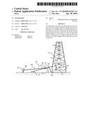
[0019] FIG. 1 is a front perspective view of the Sucker Skid SOP showing the carriage installed on the adjustable boom (slide/support rail) and locked into the upper position;
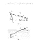
[0020] FIG. 2 is a rear perspective view of the Sucker Skid SOP showing the carriage installed on the adjustable boom and looked into the upper position;
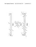
[0021] FIG. 3 is a right side view of an embodiment of the adjustable boom showing pin holes to receive removable pins in the right frame to hold the carriage in place;
[0022] FIG. 4 is a front view of the adjustable boom shown in FIG. 3 showing the middle frame between the left frame and the right frame;
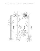
[0023] FIG. 5 is a top view of the adjustable boom shown in FIG. 3 and showing that the middle frame is connected along the length of the left frame and the right frame;
[0024] FIG. 6 is a bottom view of the adjustable boom shown in FIG. 3 and is showing mounting holes for front and rear legs;
[0025] FIG. 7 is a top view of an alternative embodiment of an adjustable boom showing multiple middle frames between the left frame and the right frame and left and right leg receivers;
[0026] FIG. 8 is a front view of the alternative embodiment of the adjustable boom shown in FIG. 7 and is showing stoppers, each including a spring loaded ball and mounting plate;
[0027] FIG. 9 is a right side view of the alternative embodiment of the adjustable boom shown in FIG. 7 and is showing pin holes sized to receive pins to lock left and right adjustable legs in place;
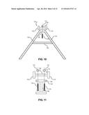
[0028] FIG. 10 is a front view assembly drawing of fixed front legs and the adjustable boom shown in FIGS. 3 through 6 and showing a fixed stabilizer bar;
[0029] FIG. 11 is a rear view assembly drawing of the rear leg and the adjustable boom shown in FIGS. 3 through 6;
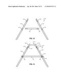
[0030] FIG. 12 is a front drawing of the component parts of an alternative embodiment of front legs with adjustable left and right front legs and adjustable stabilizer bar;
[0031] FIG. 13 is a front view of the front legs depicted in FIG. 12 and assembled to the adjustable boom depicted in FIGS. 7 through 9;
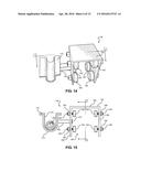
[0032] FIG. 14 is a front perspective view of the carriage having four upper wheels and four lower wheels and a cradle sized to receive a sucker rod;
[0033] FIG. 15 is a front view of the carriage of FIG. 14 and showing a sucker rod on the soft material located on the curved surface of the cradle;
[0034] FIG. 16 is cross-sectional view taken along the lines 2-2 shown in FIG. 15 and showing the top wheels in contact with the top of the left frame (shown in dashed lines) and the bottom wheels in contact with the bottom of the left frame (shown in dashed lines);
[0035] FIG. 17 is a bottom view of the carriage of FIG. 14 and showing the carriage extender between the carriage and the cradle;
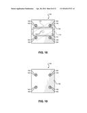
[0036] FIG. 18 is a left side view of the carriage of FIG. 14 and showing the cradle pivot about the carriage extender;
[0037] FIG. 19 is a right side view of the carriage of FIG. 14 and showing the wheel axles and the wheel nuts;
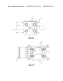
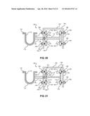
[0038] FIG. 20 is a cross-sectional view of the carriage along the lines 1-1 shown in FIG. 14 and showing the top wheels in contact with the top of the left frame and the right frame and the bottom wheels in contact with the bottom of the left frame and the right frame;
[0039] FIG. 21 is a cross-sectional view of an alternative embodiment of the carriage along the lines 1-1 shown in FIG. 14 and showing top and bottom wheels with grooves to prevent side to side movement of the carriage with respect to the boom;
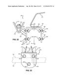
[0040] FIG. 22 is a front view of an alternative embodiment of the carriage having four upper wheels and only two lower wheels, a v-cradle sized to receive a sucker rod and a handle to allow the derrick hand to easily move the carriage from the rear of the boom to the front of the boom;
[0041] FIG. 23 is a front view of the carriage of FIG. 22 and showing a sucker rod on the soft material located on the v-cradle showing showing the top wheels in contact with the top of the left frame (shown in dashed lines) and the bottom wheels in contact with the bottom of the left frame (shown in dashed lines); and
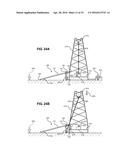
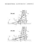
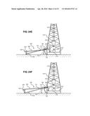
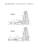
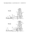
[0042] FIGS. 24A through 24J show the sequence of using the Sucker Skid during the process of laying down sucker rods.
DETAILED DESCRIPTION OF DRAWINGS
[0043] Referring initially to FIGS. 1 and 2, a front perspective view and a rear perspective view respectively of an embodiment of the Sucker Skid is shown and generally designated 100. The basic component parts of the Sucker Skid 100 include a boom 110 supported by front legs 130 and a rear leg 134, and a carriage 150 that is capable of moving along the length of the boom 110. The carriage 150 has a cradle 170 sized to receive a sucker rod 200 (not shown). The front legs 130 are longer than the rear leg 134 so as to cause the boom 110 to have an angle 102 with respect to the ground 10.
[0044] Referring next to FIGS. 3 through 6, an embodiment of the boom 110 is shown. The boom 110 generally has a height 109 and a length 111 that is substantially larger than the height. The boom 110 also has a width 107. It is to be appreciated that the width 107 and height 109 can be varied to accommodate a wide variety of geometries of carriage 150. However, in all such configurations, both the height 109 and the width 107 of the carriage will be substantially smaller than the length 111 of the boom 110. The boom 110 is made up of a left frame 112 and a right frame 114 and a single middle frame 106, each having a front 118 and a rear 120. The left frame 112 has top left 124 and a bottom left 128 opposite the top left 124. Similarly, the right frame 114 has a top right 122 and a bottom right 126. The surface of the top left 124, bottom left 128, top right 122 and bottom right 126 is smooth to allow a good rolling surface for top wheels 162 and bottom wheels 164 of the carriage 150 as set forth more fully below in conjunction with FIGS. 14 through 17.
[0045] The single middle frame 106 connects the left frame 112 to the right frame 114 and has mounting holes 119 sized to receive fasteners (not shown) to connect front legs 130 and a rear leg 134 as depicted below in FIGS. 10 and 11. It is to be appreciated that additional mounting holes 119 can be provided to allow for custom positioning of the front legs 130 and rear leg 134.
[0046] Left frame 112 has a left frame hole 113 located near the front 118 and an additional left frame hole 113 located near the rear 120. Similarly right frame 114 has a right frame hole 115 located near the front 118 and the rear 120. The left and right frame holes 113 and 115 are sized to receive a removable locking pin 117. The removable locking pin 117 is meant to be inserted into boom 110 through the left and right frame holes 113 and 115 to prevent the carriage 150 from traveling along the boom beyond the locking pin 117. Thus, when the carriage 150 is near the front 118 of the boom 110 as seen in both FIGS. 1 and 2, the locking pin 117 can ensure the carriage 150 cannot travel past the locking pin 117 thereby preventing the carriage 150 from leaving the boom 110 unless and until the removable locking pin 117 is removed.
[0047] FIGS. 7 through 9 show an alternative embodiment of the boom 110 with a left leg receiver 123 and a right leg receiver 125. The left and right leg receivers 123 and 125 are sized to fit within a left adjustable leg 136 and a right adjustable leg 138 respectively (as more fully show in FIGS. 12-13). Multiple middle frames 116 connect the left frame 112 to the right frame 114. The use of multiple middle frames 116 is an alternate embodiment to the use of the single middle frame 106. The use of multiple middle frames 116 instead of single middle frame 106 allows the boom 110 to be lighter in weight and easier to transport. The left leg receiver 123 and the right leg receiver 125 each have a plurality of pin holes 142 sized to receive a pin 144 (not shown). The boom 110 of FIGS. 7 through 9 includes a stopper system 190 that includes a spring loaded ball 192 a spring 193 (not shown) and a mounting plate 194. If the carriage 150 is manually rolled along the length 111 of the boom 110 in direction 197 with sufficient force, a top wheel 162 will overcome the force of the spring 193 causing the spring loaded ball 192 to depress within a bore 195 in the boom 110 and allow the carriage 150 to pass the stopper system 190. Once the top wheels 162 are passed the spring loaded ball 192, the spring 193 will act on the spring loaded ball 192 causing it to partially rise above the top right 122 surface of the boom 110. It is to be understood by those skilled in the art that the force of gravity acting on the carriage 150 will not be sufficient to overcome the spring force of the spring 193, thus allow the carriage to remain near the front 118 or the rear 120 of the boom 110 if positioned there by a user as set forth more fully in FIGS. 24A through 24F and 24J.
[0048] FIG. 10 is an assembly drawing showing fixed front legs 130 with a stabilizing bar 140 connecting to the middle frame 116 of the boom 110. The front legs 130 are joined to a mounting surface 135. The mounting surface 134 is connected to the middle frame 116 of the boom 110 via a fastener. The fastener depicted in FIG. 10 is a nut 131 and bolt 133, however it is to be appreciated that any fasteners known in the art would suffice.
[0049] FIG. 11 is an assembly drawings showing rear leg 134 connecting to the middle frame 116 of the boom 110. The rear leg 135 is substantially smaller than the front leg 130 in order to allow the boom 110 to have an angle 102 with respect to the ground 10. The rear leg 134 is connected to a mounting plate 135 opposite the ground 10. The mounting plate 135 is connected to the middle frame 116 of the boom 110 with fasteners. In FIG. 11, the fasteners depicted are nuts 131 and bolts 133. Optional rubber stoppers 198 (shown in phantom) are mounted to the mounting plate 135 to prevent the carriage 150 from rolling past the rear leg 134.
[0050] Referring next to FIGS. 12 through 13, the component parts of adjustable front legs 132 are shown as an alternative embodiment to the fixed front legs 130. The adjustable front legs 132 include a left adjustable leg 136, a right adjustable leg 138 and an adjustable stabilizing bar 141. The left adjustable leg 136 is sized to receive the left leg receiver 125 of the boom 110 shown in FIGS. 7 through 9. Similarly, the right adjustable leg 138 is sized to receive the right leg receiver 123 of the boom 110 shown in FIGS. 7 through 9. The left adjustable leg 136, the right adjustable leg 138 and the adjustable stabilizing bar 141 each have a plurality of pin holes 142 sized to receive a pin 144. To assemble, the left leg receiver 125 is inserted into the adjustable left leg 136 sufficiently to align a pin hole 142 of the left leg receiver 125 with a pin hole 142 of the adjustable left leg 136. Next, a pin 144 is inserted through the aligned pin holes 142 to secure the adjustable left leg 136 to the boom 110. The process is repeated to connect the adjustable right leg 138 to the boom 110 using a pin 144. Finally, pin holes 142 of the adjustable stabilizing bar 141 are aligned with pin holes 142 of the left and right adjustable legs 136 and 138 and pins 144 are inserted through the pin holes 142 to secure the adjustable stabilizing bar 141.
[0051] Referring next to FIG. 14, a front perspective view of the carriage 150 is shown. The carriage 150 has a carriage housing 152, four top wheels 162 and four bottom wheels 164. As shown more fully in FIG. 16, the top wheels 162 roll on the top right 122 and top left 124 of the boom 110 while the bottom wheels 164 are meant to roll on the bottom right 126 and bottom left 128 of the boom 110. A cradle 170 is connected to the carriage 150 by way of a carriage extender 160.
[0052] Referring next to FIG. 15, a front view of the carriage 150 is shown. The carriage housing 152 has a top 154, a right housing 156, a left housing 158 and an open bottom 159. Two of the four top wheels 162 are mounted to the right housing 156 near the top 154. Two of the four bottom wheels 164 are mounted to the right housing 156 near the open bottom 159. Similarly, the remaining two of the four top wheels 162 are mounted to the left housing 158 near the top 154 and the remaining two of the four bottom wheels 164 are mounted to the left housing 158 near the open bottom 159. Each of the four top wheels 162 and bottom wheels 164 are connected to the carriage housing 152 by way of a wheel axle 166 and wheel nut 168.
[0053] The cradle 170 has a curved surface 172 sized to receive a sucker rod 200. A soft material 174 is lined on the curved surface 172 and is meant to protect the sucker rod 200 from damage and the carriage 150 travels the length 111 of the boom 110 during the process of laying down a sucker rod 200. The soft material 174 can be made of numerous types of known soft materials such as neoprene, silicone, EDPM (Ethylene Propylene Diene Monomer), or plastic foam. The cradle 170 is mounted to the left housing 158 by way of the carriage extender 160. The carriage extender 160 can either be fixedly attached to the carriage housing 152 or rotationally attached to the carriage housing 152. Although shown connected to the left housing 158, it is to be appreciated that the carriage extender 170 and cradle 170 could alternatively be attached to the right housing 156.
[0054] Referring next to FIG. 16, a cross-sectional view along of the carriage 150 along the lines 2-2 shown in FIG. 15 is shown. The top left 124 and bottom left 128 of boom 110 are shown in dashed lines to demonstrate how two of the four top wheels 162 and two of the four bottom wheels 164 roll on the top left 124 and bottom left 128 respectively of the boom 110. It is to be appreciated that the position of the carriage 150 can be easily reversed on the boom 110 such that the cradle 170 can be near the left frame 112 or the right frame 114. Although the pivot pin cap 178 is shown in both FIGS. 15 and 16, it is more fully described in connection with FIG. 20.
[0055] Referring next to FIG. 17, a bottom view of the carriage 150 is shown. As can be seen in FIG. 17, the carriage 150 has an open width 180 that is slightly larger than the width 107 (shown in FIG. 4) of the boom 110. The slightly larger open width 180 allows the carriage 150 to fit around the left frame 112 and right frame 114 of the boom 110 so as to enable the carriage 150 to freely roll on the boom 110. The cradle 170 is separated from the carriage 150 by the length of the carriage extender 160 so that the cradle 170 does not come into contact with the wheel nuts 166 or the wheel axles 168 of the carriage 150.
[0056] FIGS. 18 and 19 depict left and right side views of the carriage 150 respectively. Wheel axles 168 and wheel nuts 166 are visible in FIGS. 15, 17, 18 and 19 and correspond in number to the number of top and bottom wheels 162 and 164 that are connected to the left housing 158 and right housing 156. It is to be appreciated that the present invention is not limited to any particular number of wheels or even the use of wheels. Any low friction material can be used on the portion of the housing 152 in contact with the boom 110 that would allow the carriage 150 to be easily moved along the length 111 of the boom 110. As can be seen in FIG. 18, in an embodiment when the cradle 170 is rotatably attached to the carriage, the cradle 170 can be rotated in rotate direction 179 about the carriage extender 160.
[0057] FIG. 20 is a cross-sectional view of the carriage 150 along the lines 1-1 shown in FIG. 14 and showing the top wheels 162 in contact with the top of the right frame and the left frame 122 and 124 and the bottom wheels 164 in contact with the bottom of the right frame and the left frame 126 and 128. It is to be appreciated that the size of the top and bottom wheels 162 and 164 can be varied to accommodate different geometries of the boom 110. The carriage extender 160 is rotatably attached to the left housing 158 by way of a carriage extender pivot pin 176 and pivot pin cap 178.
[0058] FIG. 21 is a cross-sectional view of an alternative embodiment of the carriage along the lines 1-1 shown in FIG. 14 and showing top and bottom wheels 162 and 164 with grooves 163 to prevent side to side movement of the carriage 150 with respect to the boom 110. The left and right frames 112 and 114 are shown with a small thickness 165 to allow the grooves 163 to wrap around the top right and top left 122 and 124 and the bottom right and bottom left 126 and 128 respectively. The grooves 163 keep the carriage 150 centered on the boom 110 to minimize binding or excessive friction.
[0059] FIGS. 22 through 23 show an alternative embodiment of a carriage 250 with four upper wheels 262 and only two lower wheels 264. The carriage 250 has a housing 252 with a top housing 254, a right housing 256, a left housing 258 and an open bottom 259. Two of the four upper wheels 262 are mounted to the right housing 256 near the top housing 254 with wheel axles 268 and wheel nuts 266. Similarly, the remaining two of the four upper wheels 262 are mounted to the left housing 258 near the top housing 254 with wheel axles 268 and wheel nuts 266. A single lower wheel 264 is mounted to the right housing 256 near the open bottom 259 in between upper wheels 262. Similarly, the second single lower wheel 264 is mounted to the left housing 258 near the open bottom 259.
[0060] A handle 270 is mounted to the top 254 of the housing 250 to assist a user in moving the carriage 250 along a boom 110. It is to be appreciated that a vibrant color such as red can be applied to the handle 270 to enable a user to quickly distinguish the handle 270 from the other components of the carriage 250.
[0061] A v-cradle 272 is mounted to the left housing 258 by a carriage extender 260. The v-cradle 272 has a soft material layer 274. The v-shape of the v-cradle 272 allows the v-cradle 272 to more securely hold a sucker rod 200 in place.
[0062] FIGS. 24A through 24J show the sequence of using the Sucker Skid 100 during the process of laying down sucker rods 200. FIG. 24A shows a partial view of a typical derrick 210 erected over an existing oil well (not shown). In FIG. 24A, the derrick 210 has movable blocks 212 attached to cables 214 (shown beginning in FIG. 24C), a well table 216, a well platform 218 and controls 219. A typical crew used to lay down pipe includes a floor hand 220, a derrick hand 222, an operator 223, and a fourth hand 224. The operator 223 raises and lowers the movable blocks 212 utilizing the controls 219. The operator 223 and controls 219 are omitted from FIGS. 24B through 22J as they are not needed to understand the invention. In FIG. 24A, a sucker rod 200 is shown in a vertical position with one end connected to the blocks 212 and the other end connected to a sucker rod coupling 201, which in turn is connected to a second sucker rod 203 that is down hole on the oil well and mostly obscured from view.
[0063] When laying down sucker rods, the floor hand 220 works on the well platform 218 while the derrick hand 222 and the fourth hand 224 work on the ground. It is an object of the present invention to replace the fourth hand 224 with the Sucker Skid 100, therefore in FIGS. 24A through 24J, the fourth hand 224 is shown in dashed lines.
[0064] Returning to FIG. 24A, the floor hand 220 breaks the connection between a sucker rod 200 and the sucker rod coupling 201. The sucker rod 200 is held vertically by the blocks 212. The derrick hand 222 stands near the derrick platform 218 waiting to receive a first end of the sucker rod 200 from the floor hand 220. The fourth hand 224 stands by with no job duty. The carriage 150 with cradle 170 remains in place at the front 118 of the boom 110 of the sucker skid 100 by a stopper 190 (not visible in this view).
[0065] FIG. 24B shows the floor hand 220 handing the derrick hand 222 the first end 204 of the sucker rod 200. The second end 206 of the sucker rod 200 remains connected to the blocks 212, however, is capable of pivoting with respect to the blocks. In order to hand the first end 204 of the sucker rod 200 to the derrick hand 222, the operator 223 needs to operate the controls 219 to lower the blocks 212 in direction 240 using cables 214 (not visible in this Figure). The fourth hand 224 continues to perform no job task.
[0066] FIG. 24C shows the blocks 212 continue to be lowered in downward direction 240 to allow the derrick hand 222 to walk away from the derrick 210 while carrying the first end 204 of the sucker rod 200. While the derrick hand 222 walks away from the derrick 210, the floor hand 220 remains on the derrick platform 218 and walks towards the well table 216. The fourth hand 224 continues to perform no job task while the remaining three crew members (the derrick hand 222, the floor hand 220 and the operator 223 are all performing job tasks).
[0067] FIG. 24D shows the derrick hand 222 continuing to walk away from the derrick 210 while carrying the first end 204 of the sucker rod 200. The blocks 212 are continuing to be lowered by the operator 223 toward the floor hand 220 who is now in position to grab the second end 206 of the sucker rod 200 in order to remove the sucker rod 200 from the blocks 212. The fourth hand 224 continues to have no job task.
[0068] FIG. 24E shows the derrick hand 222 continuing to walk away from the derrick 210 while the floor hand 220 carries the second end 206 of the sucker rod 200 towards the cradle 170 of the sucker skid 100. At this point the sequence of lay down a sucker rod 200, the fourth hand 224 would have the responsibility of taking the second end 206 of the sucker rod 200 from the floor hand 220. However, it is at this step in the sequence, that the fourth hand 224 is replaced by the sucker skid 100.
[0069] FIG. 24F shows the floor hand 220 placing sucker rod 200 on the cradle 170 near the second end 206. The fourth hand 224 would ordinarily be carrying the second end 206 of the sucker rod 200 while the derrick hand 222 is carrying the first end 204 of the sucker rod 200. Instead, the derrick hand 222 simply tugs on the first end 204 of the sucker rod 200 sufficiently to cause the carriage 150 to overcome the spring force of the spring loaded ball 192 of the stopper 190 to enable the carriage 150 to begin to travel from the front 118 of the boom 110 to the back 120 of the boom 110.
[0070] FIG. 24G shows the carriage 150 continuing to travel from the front 118 of the boom 110 to the back 120 of the boom 110. The second end 206 of the sucker rod 200 is fully supported by the cradle 170 of the carriage 150, ensuring that the second end 206 is protected from dirt, debris and damage as it moves away from the derrick 210. The fourth hand 224 is shown in the position he would normally occupy if the present invention were not being utilized in the laying down process. Meanwhile the floor hand 220 returns to the well table 216 in order to remove the coupling 201 from a second sucker rod 203.
[0071] FIG. 24H shows the carriage 150 arrive at its resting place at the rear 120 of the boom 110. At this stage ordinarily, the derrick hand 222 and the fourth hand 224 would lower the first end and second end 204 and 206 of the sucker rod 200 onto storage blocks or a trailer. Instead, the derrick hand 222 simply places the first end 204 of the sucker rod 200 onto a storage block. Meanwhile, the floor hand 220 removes the sucker rod coupling 201 from the second sucker rod 203 in preparation for connecting the second sucker rod 203 to the blocks 212.
[0072] FIG. 241 shows the derrick hand 222 at the second end 206 of the sucker rod 200 to remove the second end 206 from the cradle 170 of the carriage 150. Meanwhile the operator 223 lowers the blocks 212 further in direction 240 to enable the floor hand 220 to connect the blocks 212 to the second sucker rod 203. Once so connected, the blocks 212 can be raised to remove the entire second sucker rod 203 from the oil well so that it can be laid down in an identical process as the first sucker rod 200 was laid down. At this stage, the fourth hand 224 would simply be waiting again for the next sucker rod.
[0073] FIG. 24J shows the second sucker rod 203 lifted from the oil well by the blocks 212. The floor hand 220 begins the process of disconnecting the second sucker rod 203 from another coupling 207. A third sucker rod 205 is partially visible and also connected to the coupling 207. The derrick hand 222 returns the carriage 150 to the front 118 of the boom 110 and pushes the carriage 150 with sufficient force to overcome the stopper 190. Once the carriage 150 is released by the derrick hand 222, the carriage 150 settles against the spring loaded ball 192 and rests near the front 118 of the boom 110 awaiting the second sucker rod 203. Similarly, the derrick hand 222 is now in position to receive a first end 209 of the second sucker rod 203. And the steps shown in FIGS. 24A through 24J are repeated to lay down the second sucker rod 203. Through using the sucker skid 100, the entire job function of the fourth hand 224 is eliminated. It is to be appreciated that sucker rods can be installed in an oil well utilizing the sucker skid 100 by simply reversing the steps shown in FIGS. 24A trough 24J.
[0074] While there have been shown what are presently considered to be preferred embodiments of the present invention, it will be apparent to those skilled in the art that various changes and modifications can be made herein without departing from the scope and spirit of the invention.
User Contributions:
Comment about this patent or add new information about this topic:
Images included with this patent application:
 |  |
 |  |
 |  |
 |  |
 |  |
 |  |
 |  |
 |  |
| New patent applications in this class: | |
| Date | Title |
|---|---|
| 2016-03-17 | System for manipulating tubulars for subterranean operations |
| 2011-08-04 | Pipe handling system for a drilling rig |
| Top Inventors for class "Material or article handling" | |
| Rank | Inventor's name |
|---|---|
| 1 | Christopher Hofmeister |
| 2 | Peter Van Der Meulen |
| 3 | Jeffrey C. Hudgens |
| 4 | John Oren |
| 5 | Martin Hosek |