Patent application title: EXPANDABLE MULTIMODAL TRANSPORT CONTAINER
Inventors:
Mohamed Sahbi Miled (Sayada, TN)
IPC8 Class: AB65D8800FI
USPC Class:
220 15
Class name: Receptacles freight containers
Publication date: 2016-04-28
Patent application number: 20160114968
Abstract:
The present invention relates to the field of ISO containers that are
adjustable lengthwise, and more specifically to an optimised use of such
adjustable ISO containers. This invention, and the claims related to
same, were the subject of a patent application filed in France in late
May 2013 by the same applicant and inventor, Mr. Mohamed Sahbi Miled.
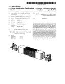
FIG. 1 illustrates a three-dimensional view of the solution, an example
of an ISO container according to the present invention in the elongated
configuration of same. In particular, FIG. 1 illustrates a fixed central
portion (1) corresponding to an ISO container of size A, which is
equivalent to a length L0 of twenty (20) feet; a left-hand movable
portion (2a) of size ((B-A)/2)), which is equivalent to a length L2 of
ten (10) feet; and a right-hand movable portion (2b) of size ((B-A)/2)),
which is equivalent to a length L1 of ten (10) feet.Claims:
1. A container compliant to the ISO adjustable standards. This container
is made of a characterized central element which comprises a fixed
central part corresponding to a container that respects the ISO standards
of Dimension A. It comprises also two integral parts with the central
fixed part; they are movable in the sens of length and they are
deployable of the central fixed part. They permit the transformation of
the container of the dimension A into a container of dimension B which is
larger than A.
2. In accordance with the first claim, the ISO container shall be characterized in the way that its dimension A corresponds to a container of 20 feet and that its dimension B corresponds to a container of 40 feet.
3. In accordance with one of the previous claims, the container ISO's two movable parts are of the same length and are integral in the compact central part.
4. In accordance with one of the previous claims, the container ISO shall contain 8 corner pieces on its fixed part (four on its upper wall and four on the lower wall) and 8 other pieces of the moving corner (two on each of the upper wall of the two moving parts, two on each of lower wall of the two moving parts.)
5. According to one of the previous claims, the ISO container shall at least include an integral system which must preferably include by itself a system of linear guidance which permits the movement of the two moving parts with regard to the fixed part of the container.
6. According to the previous claim, the ISO container shall be characterised by a intergral system that also includes: a) A rigid moving axis with the guidance system. Its length is equivalent to the maximal length available on wall that corresponds to the fixed part b) A system of security stop that allows the control of two moving parts' movement between their position in the compact mode and their position in the stretched mode.
7. According to the previous claim, the ISO container shall contain an autonomous or semi-autonomous instrument that ensures the movement of the two moving parts with regard to the central fixed part. This instrument should preferably be electrical, mechanical, hydraulic, and/or electrohydraulic.
8. According to one of the previous claims, the movable parts of the ISO container shall include or shall be made of lighter materials which should have a better thermal insulation than the fixed part.
9. Used for the transportation of goods by ISO container of dimension A and dimension B using the same adjustable ISO container according to one of the previous assertions.
10. A procedure of optimization of goods transportation by use of the container compliant with the ISO standards adjustable according to any one of claims from 1 to 8.
Description:
[0001] The present invention relates to the field of ISO containers that
are adjustable lengthwise, and more specifically to an optimised use of
such adjustable ISO containers. This invention and the claims related to
the same, were the subject of a patent application filed in France in the
late May 2013 by the same applicant and inventor Mr. Mohamed Sahbi Miled.
[0002] The intermodal container is a reusable and standardized box (better be a parallelepiped), generally made of steel used for the storage and transportation of goods. The intermodal system of transportation of the goods is global and it allows a safe and efficient movement of goods. The term intermodal indicates that the container can be moved from one means of transport to another (maritime, fluvial, railway, roads) without interruption of the loading process which means without unloading and reloading the container's content. Each container has a unique identification mark allocated to it by the ISO's standard 6346. The containers' length varies between 8 feet (2,438 m) and 56 feet (17,07 m) as for their height, it varies from 8 feet (2,438 m) to 9 feet and 6 inches (2,9 m). The containers' capacity is often expressed in units equivalent to twenty feet (this capacity is equal to a standard length of 6.10 m and 2.44 m wide). We will then call them the `ISO containers " because they must abide by the ISO requirements enforced at time of manufacture taking the example of transport which shall enable the transportation by truck, train, boat and/or barge. We may also refer to ISO standard 568:1995 (which defines containers of 10, 20, 30 and 40 feet) and/or more recently with ISO 668:2013; whose contents are incorporated herein by reference.
[0003] The present invention relates to the field of ISO containers that are adjustable lengthwise, and more specifically to an optimised use of such adjustable ISO containers. As described below, as the ISO standardization of container transport has contributed significantly to a rationalization of transport containers worldwide, the Applicant has developed a critical improvement in container transportation system that will better manage the movements of goods around the world. In fact, globalization entails unbalanced movements of goods via container which can not be controlled and/or optimized due to mobility in supply and demand on a global scale. So it happens frequently that the containers that have traveled from one point to another are found either in storage mode at the destination, or leave empty and/or partially filled to another destination. So there is indeed a need for optimization of container transport while abiding by the international standards. Some solutions to improve the field of transportation through a container have been described in the prior art. Thus, there is also prior art relative to:
[0004] The pliable containers in a way to optimize the empty transport of containers,
[0005] Containers whose some sides are removable so as to facilitate loading and/or unloading of goods, and
[0006] Containers made of materials other than steel so as to reduce their weight.
[0007] In addition, the prior art also describes some examples of adjustable containers. We may mention for example the international patent WO2011110725 application concerning a suitable container, equipped with means to vary its dimensions so that the columns of the lateral, frontal and posterior frame and walls are extensible from a standard container to a double height container. The application needed particularly for such containers concerns the habitat; In fact, FIG. 10 of WO2011110725 shows a modular set obtained by grouping together various containers and attaching them to each other (including a stack) to form a house, a show room, or place for entertainment, . . .
[0008] In fact, the great majority of adjustable containers meets other objectives rather than the optimization of transportation which is manifestly apparent in the fact that these containers are not often ISO Containers because they do not comply with the ISO requirements relatives to transportation and handling through containers. This may probably be due to the fact that the main application developed on the basis of adjustable containers during the last decades is generically related to habitat as described above.
[0009] Moreover, there is always a need to the transportation through ISO containers. So this invention concerns mainly the field of ISO adjustable containers regarding their length and more specifically the best use of such containers.
[0010] The ISO container is an instrument of transportation which should:
[0011] Have a durable feature and therefore so strong to withstand various uses.
[0012] Be designed in a way to facilitate the transport of properties through various means of transportation without interruption.
[0013] Be equipped with accessories which allow simple handling and more specifically the transport from one means of transportation to another.
[0014] Be designed in a way to be filled and unloaded easily.
[0015] Have an interior volume of 1 m3 (cube) or more.
[0016] Preferably, it can be stacked.
[0017] Comply with the ISO standards which are relevant to the existing containers used and in force at the moment of its production (they should also comply with the relevant security standards)
[0018] In addition, in accordance with the execution mode of this invention, this objective can be achieved thanks to an adjustable ISO container made of a characterised central element which contains a fixed central part that corresponds to an ISO container of dimension A and two inerdependent parts of the central fixed part. Those two independant parts can move in each side of the central fixed part and enabling the transformation of the container from dimension A in a dimension B greater than A.
[0019] The present invention relates to the field of ISO adjustable containers consists of a central element characterised in that said central fixed member corresponding to an ISO container that have a size A with two integral portions of the central fixed part, moving lengthwise and crosswise and deployable on either side of the fixed central portion, and enabling the transformation of the container from dimension A in a dimension B greater than A.
[0020] The present invention also relates to a method for optimizing the transport of goods by the use of adjustable ISO container as claimed.
[0021] This invention with its features and advantages would be clarified following the reading of the description done in reference to the enclosed figures:
[0022] FIG. 1 illustrates a three-dimensional view of an ISO container sample according to this invention in its stretched configuration
[0023] FIG. 2 illustrates a three dimensional view of an example of the ISO container according to this invention in its stretched configuration which is realised through a motorized instrument shown also in the figure.
[0024] FIG. 1 illustrates particularly:
[0025] A central fixed portion (1) corresponding to an ISO container of dimension A equivalent to a length of twenty (20) feet;
[0026] A left movable part (2a) of dimension ((BA)/2)) equivalent to a length L2 of ten (10) feet; and
[0027] A right movable part (2b) of dimension ((BA)/2)) equivalent to a length L1 of ten (10) feet. Thus, the stretched configuration ("stretched mode") according to FIG. 1 which illustrates a container of dimension B equivalent to a total length of forty (40) feet.
[0028] The compact configuration ("compact mode") of the container of FIG. 1--although not shown--can easily be deduced from this Figure when the two movable parts are fully combined with the central portion. Thus, the compact configuration obtained by using the container according to FIG. 1 is a container of dimension A equivalent to a total length of twenty (20) feet.
[0029] As this invention is not limited only to containers of the dimensions 20 and 40 feet--we can actually take advantage of this invention with containers having different dimensions in a compact and/or stretched-configuration; this type of combination of dimensions constitutes a preferred embodiment of the present invention as explained below. An essential feature of the present invention consists of the adjustable ISO container that should retain its characteristics and its ISO requirements in all configurations, the latter are compact or stretched.
[0030] According to the present invention, the adjustable container should include corner pieces that allow the loading and/or stacking of the container with other containers (and vice verse) in a conventional manner. Thus, according to the present invention the container, in its compact configuration, comprises at least four corner fittings either on its upper face or on its lower face. It would preferably be at least four corner fittings on each of these two sides or eight corner pieces. These corner pieces are arranged at the four/eight extremities of sides--in accordance with ISO standards for existing and enforced containers and in force at the time of manufacture (e.g. ISO 668:1995; and, in particular, its Annex A)--so as to allow the stack and/or loading.
[0031] Similarly, according to the present invention, the container, in its stretched configuration, should also include at least four corner fittings on its upper face or on its lower face; it would preferably be at least four corner fittings on each of these two faces, eight corner pieces. These corner pieces are arranged at the four/eight ends of the sides as to permit the process of stacking.
[0032] On a preferred configuration of the adjustable container of this invention, the movable portions which merge with the fixed central portion in compact mode have an identical length. The interlocking between the movable parts and the stationary core may be anyway-appropriate-for-as-than-container-retains-feature-ISO-in-all-its possible configurations. In a better configuration of the adjustable container of this invention, the movable portions which merge with the fixed central portion in compact mode have an identical length. The interlocking between the movable parts and the stationary core can be anyway-appropriate as then the container can retain its ISO feature in all its possible configurations.
[0033] For example, the movable lateral portions which merge with the central fixed part shall either surrounder the central fixed part or shall be part of the central fixed part in a compact mode(this would constitute a good configuration according to this invention. (FIG. 1)
[0034] In the last configuration, the corner pieces of the amovable portions will be better movable in order to prevent the perturbation of the movement of the movable portions inside the fixed part. In a configuration which precedes the last configuration the corner pieces of the central fixed part shall be better movable in order to prevent the perturbation of the movement of the movable portions inside the fixed part.
[0035] Thus, in a preferred configuration of the adjustable container according to the present invention, this container shall contain at least sixteen corner fittings, at least eight of them are on its upper surface and at least other eight ones on its lower side; and it would be preferable that at least eight of them are removable. In another configuration or a proposed technical solution, each of the containers will be equipped with two removable corner pieces on the top and it should be laterally movable to enable the full entry of the containers in the mother container.
[0036] These corner pieces being moved with a guided screw through an oblong hole will be set at the desired position according to the position of the container sons. If the son containers are in closed position to have the size of 20 feet, these corner pieces will not be functional. However, if the son containers are in open position, ie there will be a container of 40 feet dimension, these corner pieces will be functional and used for fixing the container and optionally to the handling of the container.
[0037] Also, each son containers comprises two corner pieces laid down. The container is also equipped with a pin axis that will be positioned according to the desired dimensions (45, 40 30, 20, 10 . . . ) The container according to the present invention can also be provided with additional anchor points.
[0038] The two moving parts in the sense of the length and deployable of the fixed central portion are therefore interdependent to the fixed central portion. This interdependence can be obtained by any suitable means provided that the container maintains its ISO feature in all its possible configurations. We will call it later the "integral system" and we may mention for examples of the linear guide systems, eg linear roller guidance systems, the tables of guidage, roller systems/rail, the guide rails with cage, the pneumatic linear guidage module, etc.
[0039] In a configuration mode of the container according to this invention, the integral system comprises at least one system of linear guidance. It would be better at least two linear guidance systems to allow the mobility of deployable parts with regard to the fixed part of the container. These guidance systems can be placed on any integral longitudinal sides of the movable parts and on the fixed part of the container, for example only on their upper walls, or preferably at both their upper and lower walls or on all of their longitudinal walls. Moreover, in a preferred execution mode, the integral system of the container according to the present invention comprises at least four linear guidance systems in which at least two are on the upper walls and at least two on the lower walls; it is also possible to add at least one linear guidance system positioned on the longitudinal side walls of the container.
[0040] In a sample container of the configuration mode of this present invention, the integral system shall also comprise a rigid, movable axis in the guidance system, this axis' length must be substantially equivalent to the maximum length provided on the corresponding wall of the fixed part. This type of configuration allows the preservation of ISO container features in elongated fashion and thus its rigidity. For example, we may refer to the illustration of FIG. 1: in this particular configuration, each approximately half of the rigid axis will respectively remain integral with the fixed part and the moving part. one feature of these configurations of this type is that the guidance system of the movable portion of left is not aligned with the guidance system of the mobile part of the right container.
[0041] In an example of container configuration mode according to the present invention, the solidarity system also includes safety shutdown systems to control the movement of moving parts between their position corresponding to the compact mode and position corresponding to the stretched mode. These safety shutdown systems can be achieved by any suitable means. We may mention for example a safety shutdown system of the axis type which allows to confer more stability to the moving parts. In a particular mode according to this invention, the container comprises at least two safety shutdown systems, one for each movable part.
[0042] Any other type of integral system may also be used provided that it allows the mobility of movable parts with regard to the fixed part and provided that the container maintains its ISO feature in all its possible configurations.
[0043] According to this invention, the two integral portions of the central fixed part of the container and deployable on both sides of the fixed central portion, are movable and preferably of identical length.
[0044] According to a preferred mode of this invention, when the container is stretched mode, the dimensions of the moving parts that surpass the fixed part are identical. The mobility of the container's deployable according to the present invention may be implemented by any appropriate means; this mobility can be autonomous, semi-autonomous or forced as explained below.
[0045] One of the technical solutions that we developed and which has undergone all the tests and calculation RDM, finite element resistance is the following: with a guidance system in translation by rollers positioned laterally as well as a system composed of ball bushing which will be placed at the top and bottom, both son containers make lateral movements within the parent container. The latter guidance system in translation by rolling elements ensures proper operation and reduces friction phenomena. The solutions used have been designed and manufactured from these pieces (standard guide elements).
[0046] The mother container is manifested as a joined structure in the form of a metallic corridor.
[0047] The joined parts are of simple and standard geometries and are commercially available.
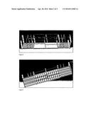
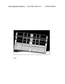
[0048] The lateral sides are made from sheet metal siding like conventional containers. As for the ceiling, it is made from sheets metal containing EPE beams to ensure the maintenance and proper functioning of the rails. To facilitate the movements of the son container movements, the mother container will also include bushings and rollers. (FIGS. 3,4 and 5)
[0049] As far as the son containers are concerned, each one will be equipped of two top laterally removable corners to enable their full input in the mother container. These corner pieces being moved with a guided screw through an oblong hole will be fixed at the desired position according to the position of the containers son. If the son containers are in a close position to obtain the 20 feet dimension "these corner pieces will not be functional. However, if the son containers are in an open position, ie we will have a 40 feet container dimensions, these corner pieces will be functional and used for fixing the container and optionally to the handling of the container. Each of the son containers comprises two corner pieces fixed down.
[0050] Referring to FIG. 2, the illustrated mobility is of the type "forced" because it is made using a motorized instrument (eg truck type forklift, etc . . . ) that allows to pull the moving parts in order to deploy the container to its stretched mode and/or push the moving parts in order to bring the container to compact mode.
[0051] Opening and closing as well as gathering the removable parts can be made by a fixed station dedicated to this new type of container.
[0052] For example, the other means that permit the movement of the container's moving parts, we may mention electrical, mechanical systems (endless screw, linear guidance table, rail-roller rack), hydraulic and/or electro-hydraulic, such as hydraulic cylinders, all types of electric motor, any type of crane, etc. A source of electrical energy or a battery can be advantageously used for some of the ways mentioned above.
[0053] The adjustable ISO container can easily be adapted to become an automated system of the variable structure. The use of cylindrical supports (see FIG. 1) is possible to improve the resistance of the eight removable wedges (not welded). To dampen vibrations, a rubbery material can be used especially at the corners.
[0054] During the storage process, the eight corners of ISO adjustable container can withstand the loading of 5 containers of 40 feet; as for the handling, it may be done by the four corners packed on the fixed central portion. For example, each secured part must bear a maximum load of 7 tons of goods and the adjustable ISO container carries a maximum of 30 tonnes.
[0055] According to a preferred mode of this invention, and this regardless of the means to ensure the movement of the movable parts of the container according to the present invention, the movement of the movable parts towards the stretched and compact modes of the container will be done synchronously.
[0056] The great part of an ISO adjustable container according to this invention can be made of steel (e.g. S355 having a high elastic limit). The two moving parts can also include and/or be made of lighter materials while maintaining the features of strength and durability essential to the conservation of their destination ISO. As non-limiting examples include the use of reinforced aluminum and/or any metal or combination of light metal with high mechanical strength (e.g., titanium) and having a thermal insulation better than that of the steel. We can equally use heterogeneous materials and/or plastics. Removable parts can be lightweight material (e.g. aluminum alloy) to facilitate manual assembly.
[0057] To ensure longer life to an adjustable container in an aggressive environment, we must achieve better corrosion resistance. That is why we propose the metal coating as it offers excellent protection against corrosion.
[0058] According to a preferred mode of this invention, the movable parts of the container comprise and/or are made of lighter materials than the fixed part. They may also consist of refrigerated walls for a refrigerating container in a compact mode.
[0059] This invention is equally concerned with the use of an adjustable ISO container made of a central element which comprises a fixed central portion corresponding to an ISO container of size A and two integral portions of the central portion fixed. They are movable lengthwise and deployable on either side of the fixed central portion; they also permit transformation of a container of A dimension into a container of B dimension of upper. This use concerning the carriage of goods through an ISO container Of A dimension and another ISO container of B dimension at least the use of the same adjustable ISO container.
[0060] This use permits, therefore, to adapt the containers according to the transported goods and/or depending on the fact that we must carry the load to another destination. This invention also will allow to have a container which adapts to the nature of the goods so we can get an open top container from a dry container or also a refrigerated container.
[0061] Thus, this invention can significantly reduce the transport costs of empty containers and/or partially filled. Thus, this invention contributes to the respect of the environment by optimizing the transport of goods and the number of empty trips. Finally, this invention would improve the containers' insulation.
[0062] It would also concern a process of optimization by the use of adjustable ISO container as claimed. This optimization can also be obtained with a new concept called it split container, which consists of manufacturing small containers of the lengths 5 or 10 feet and width of 8 feet or 4 and which will be stuck at the level of corner pieces with a new tool. Thus to obtain an ISO container of 20 feet we should gather the four containers of the length of 5 feet and 8 feet wide one next to another I or by combining 8 containers of dimensions 5 by 4 feet.
[0063] It must be obvious to the skilled person that the present invention allows modes of realizations in many other specific forms without getting away from the scope of the invention as claimed. Thus, the present modes should be considered illustrative but can be modified within the field defined by the scope of the enclosed claims.
User Contributions:
Comment about this patent or add new information about this topic:
Images included with this patent application:
 |  |
 |  |
| Similar patent applications: | |
| Date | Title |
|---|---|
| 2016-03-31 | Invertible segmented consumption container |
| 2016-05-12 | Methods for fuel tank recycling and net hydrogen fuel and carbon goods production along with associated apparatus and systems |
| 2016-05-12 | Disposable insulating container |
| 2016-01-14 | A flexible lightweight container |
| 2016-05-12 | Combined measuring cup for mixing containers |
| New patent applications in this class: | |
| Date | Title |
|---|---|
| 2017-08-17 | Vacuum heat-insulating material, and heat-insulating container, dwelling wall, transport machine, hydrogen transport tanker, and lng transport tanker equipped with vacuum heat-insulating material |
| 2016-09-01 | Novel collapsible container |
| 2016-05-26 | Modular shipping container having hinged doors, system, and method |
| 2016-05-26 | Modular shipping container, system, and method |
| 2016-05-19 | Cargo shipping container with top-access roof cover |
| Top Inventors for class "Receptacles" | |
| Rank | Inventor's name |
|---|---|
| 1 | Daniel Lee Bizzell |
| 2 | Frank Yang |
| 3 | Terry Vovan |
| 4 | William P. Apps |
| 5 | Lowell L. Wood, Jr. |