Patent application title: PACKAGING BOX FOR ELECTRONIC DEVICE
Inventors:
Chiu-Chu Huang (New Taipei, TW)
IPC8 Class: AB65D8105FI
USPC Class:
206486
Class name: Special receptacle or package article held in aperture in base
Publication date: 2016-04-28
Patent application number: 20160114954
Abstract:
The packaging box includes a holder and a housing. The holder includes a
number of supporting plates overlapped together. Each of the number of
supporting plates defines a number of receiving holes. The housing
defines a receiving space to receive the holder and packages the holder
in the receiving space. Some of the supporting plates and the housing
cooperatively form a number of receiving chambers having different
depths.Claims:
1. A packaging box comprising: a holder, the holder comprising a
plurality of supporting plates overlapped together, each of the plurality
of supporting plates defining a plurality of receiving holes; and a
housing defining a receiving space to receive the holder and packaging
the holder in the receiving space; wherein some of the supporting plates
and the housing cooperatively form a plurality of receiving chambers
having different depths.
2. The packaging box of claim 1, wherein the housing comprises a top plate, a first side plate, a bottom plate, a second side plate, and a latching plate foldably connected to each other; the holder is placed on the bottom plate; the top plate and the first side plate are attached to a top surface and one side surface of the holder, the second side plate and the latching plate are attached to another side surface of the holder and the top.
3. The packaging box of claim 2, wherein the housing further comprises a pair of latching members positioned on the top plate and the latching plate, the latching members engage with each other to maintain the holder in the receiving space.
4. The packaging box of claim 3, wherein the latching members include a protrusion protruding from one of the top plate and the latching plate and a latching hole defined in another one of the top plate and the latching plate.
5. The packaging box of claim 1, further comprising a sleeve sleeved outside the housing.
6. The packaging box of claim 1, further comprising a buffer attached to the housing and covering one of the receiving chambers.
7. The packaging box of claim 1, wherein each supporting plate is made of a plurality of bases overlapped and adhered together.
8. A packaging box comprising: a holder, the holder comprising: a first supporting plate defining a first receiving hole and a second receiving hole; a second supporting plate defining a third receiving hole and a fourth receiving hole; a third supporting plate defining a fifth receiving hole, a sixth receiving hole, and a seventh receiving hole; and a housing defining a receiving space to receive the holder and packaging the holder in the receiving space; wherein the first, second, and third supporting plate are overlapped together; the first receiving hole and the housing form a first receiving chamber; the third receiving hole, the sixth receiving hole, and the second supporting plate form a second receiving chamber communicating with the first receiving chamber; the fourth receiving hole, the seventh receiving hole, and the bottom plate form a third receiving chamber; the fifth receiving hole and the second supporting plate form a fourth receiving chamber.
9. The packaging box of claim 8, wherein the housing comprises a top plate, a first side plate, a bottom plate, a second side plate, and a latching plate foldably connected to each other; the holder is placed on the bottom plate; the top plate and the first side plate are attached to a top surface and one side surface of the holder, the second side plate and the latching plate are attached to another side surface of the holder and the top.
10. The packaging box of claim 9, wherein the housing further comprises a pair of latching members positioned on the top plate and the latching plate, the latching members engage with each other to maintain the holder in the receiving space.
11. The packaging box of claim 10, wherein the latching members are a protrusion protruding from one of the top plate and the latching plate and a latching hole defined in another one of the top plate and the latching plate.
12. The packaging box of claim 8, further comprising a sleeve sleeved outside the housing.
13. The packaging box of claim 8, further comprising a buffer attached to the housing and covering one of the receiving chambers.
14. The packaging box of claim 8, wherein each supporting plate is made of a plurality of bases overlapped and adhered together.
Description:
FIELD
[0001] The subject matter herein generally relates to packaging boxes, and particularly to a packaging box for electronic devices.
BACKGROUND
[0002] To prevent fragile precision electronic devices, such as mobile phones, from being damaged during transportation, the electronic devices are packaged in boxes before shipment. However, most of the boxes have complex structures to provide a plurality of receiving spaces to accommodate the electronic device and corresponding accessories.
BRIEF DESCRIPTION OF THE DRAWINGS
[0003] Many aspects of the present disclosure can be better understood with reference to the drawings. The components in the drawings are not necessarily drawn to scale, the emphasis instead being placed upon clearly illustrating the principles of the disclosure. Moreover, in the drawings, like reference numerals designate corresponding parts throughout the views.
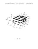
[0004] FIG. 1 is a partial, isometric view of one embodiment of a packaging box in an open state.
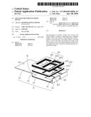
[0005] FIG. 2 is an exploded, isometric view of the packaging box of FIG. 1.
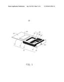
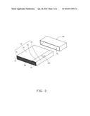
[0006] FIG. 3 is a partially assembled, isometric view of the packaging box of FIG. 1.
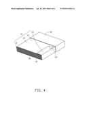
[0007] FIG. 4 is an isometric view of the packaging box of FIG. 3 in a closed state.
DETAILED DESCRIPTION
[0008] It will be appreciated that for simplicity and clarity of illustration, where appropriate, reference numerals have been repeated among the different figures to indicate corresponding or analogous elements. In addition, numerous specific details are set forth in order to provide a thorough understanding of the embodiments described herein. However, it will be understood by those of ordinary skill in the art that the embodiments described herein can be practiced without these specific details. In other instances, methods, procedures, and components have not been described in detail so as not to obscure the related relevant feature being described. Also, the description is not to be considered as limiting the scope of the embodiments described herein. The drawings are not necessarily to scale and the proportions of certain parts may be exaggerated to better illustrate details and features of the present disclosure.
[0009] Several definitions that apply throughout this disclosure will now be presented.
[0010] The term "outside" refers to a region that is beyond the outermost confines of a physical object. The term "substantially" is defined to be essentially conforming to the particular dimension, shape, or other feature that the term modifies, such that the component need not be exact. For example, "substantially cylindrical" means that the object resembles a cylinder, but can have one or more deviations from a true cylinder. The term "comprising," when utilized, means "including, but not necessarily limited to"; it specifically indicates open-ended inclusion or membership in the so-described combination, group, series and the like.
[0011] FIG. 1 is a partial, isometric view of one embodiment of a packaging box 100 in an open state. The packaging box 100 is used to accommodate an electronic device (not shown) and accessories (e.g. an earphone, a charger, a data cable, an owner manual, and the like). The packaging box 100 includes a housing 10, a buffer 20 attached to the housing 10, a holder 30 received in the housing 10 and packaged by the housing 10, and a sleeve 50 (shown in FIG. 4) sleeved outside the housing 10.
[0012] The housing 10 is a flat plate made of transparent material, hardboard, plastic board, or other suitable material. The housing 10 includes a top plate 12, a first side plate 13, a bottom plate 14, a second side plate 15, and a latching plate 16 foldably connected to each other. Sizes and shapes of the top plate 12 and the first side plate 13 are substantially the same as those of the bottom plate 14 and the second side plate 15, respectively. The first side plate 13 and the second side plate 15 can be folded relative to the bottom plate 14 to cooperatively form a substantial rectangular receiving space 17 (shown in FIG. 3) with the bottom plate 14. The receiving space 17 is configured for receiving the holder 30. The top plate 12 and the latching plate 16 can be folded relative to the first side plate 13 and the second side plate 15, respectively to package the holder 30 received in the receiving space 17.
[0013] The housing 10 further includes a pair of latching members configured for latching the latching plate 16 to the top plate 12 and maintaining the holder 30 in the receiving space 17. In this exemplary embodiment, the pair of latching members includes a protrusion 121 protruding from the top plate 12 facing the receiving chamber 17 and a corresponding latching hole 161 defined in the latching plate 16. In other embodiments, the protrusion 121 may protrude from the latching plate 16, and the latching hole 161 may be defined in the top plate 12. In addition, the pair of latching members may be two magnetic members positioned on the top plate 12 and the latching plate 16, respectively.
[0014] The buffer 20 is made of cushioning material such as foam. The buffer 20 is attached to an inner surface of the top plate 12. The buffer 20 is configured for protecting the electronic device received in the holder 30.
[0015] FIG. 2 shows the holder 30 is configured for receiving the electronic device and the accessories. The holder 30 includes a plurality of supporting plates defining a plurality of receiving holes. The supporting plates are overlapped together to form a plurality of receiving chambers having different depths.
[0016] In this exemplary embodiment, there are three supporting plates defined as a first supporting plate 31, a second supporting plate 33, and a third supporting plate 35. The first, second, and third plates 31, 33, 35 are made of a plurality of bases overlapped and adhered together. The base may be a paper board, or a wood board. In this exemplary embodiment, the base is made of corrugated board.
[0017] A first receiving hole 312 and a second receiving hole 314 are defined in the first supporting plate 31. A third receiving hole 331 and a fourth receiving hole 333 are defined in the second supporting plate 33 corresponding to the first receiving hole 312 and the second receiving hole 314, respectively. A fifth receiving hole 351, a sixth receiving hole 353, and a seventh receiving hole 355 are defined in the third supporting plate 35. The fifth receiving hole 351 is adjacent to the sixth and seventh receiving holes 353, 355. The sixth receiving hole 353 corresponds to the first receiving hole 312 and the third receiving hole 331. The seventh receiving holes 355 corresponds to the second receiving hole 314 and the fourth receiving hole 333. Sizes and shapes of the third receiving hole 351 and the fourth receiving hole 333 are the same as those of the sixth receiving hole 353 and the seventh receiving hole 355, respectively.
[0018] The first, second and third supporting plates 31, 33, 35 are overlapped together to form the holder 30. A thickness of the holder 30 is substantially equal to a depth of the receiving space 17 (i.e. a height of the first side plate 13).
[0019] The first receiving hole 312 and the bottom plate 14 form a first receiving chamber 37. The third receiving hole 331, the sixth receiving hole 353, and the second supporting plate 33 form a second receiving chamber 38 communicating with the first receiving chamber 37. The fourth receiving hole 333, the seventh receiving hole 355, and the bottom plate 14 form a third receiving chamber 39. The fifth receiving hole 351 and the second supporting plate 33 form a fourth receiving chamber 40.
[0020] The first, second, third, and fourth receiving chambers 37, 38, 39, 40 have different depths. The first, second, and third receiving chambers 37, 38, 39 are configured for receiving the accessories. The fourth receiving chamber 40 is configured for receiving the electronic device. Because bottoms of the first, second, third, and fourth receiving chambers 37, 38, 39, 40 are formed by at least one of the bottom plate 14, the first supporting plate 31, and the second supporting plate 33 which can also act as buffering layers, the electronic device and the accessories received in the first, second, third, and fourth receiving chambers 37, 38, 39, 40 can be effectively protected from impact forces such as those occurring when the packaging box 100 is dropped, or when struck by another object, especially the fourth receiving chamber 40. In other embodiment, the number of the receiving chambers can be adjusted by increasing or reducing a number of the receiving holes according to actual needs.
[0021] The sleeve 50 is configured for packaging the housing 10. The sleeve 50 is substantially a hollow box having an opening 51. The housing 10 can be slide into the sleeve 50 via the opening 51.
[0022] To package the electronic device and the accessories in the packaging box 100, the holder 30 is placed on the bottom plate 14. The accessories are received in the first, second, and third receiving chambers 37, 38, 39. The electronic device is received in the fourth receiving chamber 40. The top plate 12 and the first side plate 13 are folded relative to the bottom plate 14 until the first side plate 13 is attached to one side surface of the holder 30 and the top plate 12 is attached to a top surface of the holder 30 with the buffer 20 covering the fourth receiving chamber 40. The second side plate 15 and the latching plate 16 are folded relative to the bottom plate 14 until the second side plate 15 is attached to another side surface of the holder 30 and the latching plate 16 is attached to the top plate 12 with the protrusion 121 latched in the latching hole 161. Therefore, the holder 30 received with the electronic device and the accessories are packaged by the housing 10. The sleeve 50 is sleeved outside the housing 10 via the opening 51.
[0023] The packaging box 100 defines a plurality of the receiving chambers for accommodating the electronic device and the accessories by the holder 30 which has a relative simple structure. In addition, the electronic device and the accessories can be effectively protected due to buffering effect of the receiving chambers.
[0024] It is to be understood, however, that even through numerous characteristics and advantages of the present disclosure have been set forth in the foregoing description, together with details of assembly and function, the disclosure is illustrative only, and changes may be made in the details, especially in the matters of shape, size, and arrangement of parts within the principles of the disclosure to the full extent indicated by the broad general meaning of the terms in which the appended claims are expressed.
User Contributions:
Comment about this patent or add new information about this topic:
Images included with this patent application:
 |  |
 |  |
 |
| Similar patent applications: | |
| Date | Title |
|---|---|
| 2016-04-28 | Packaging box for electronic device |
| 2016-04-28 | Packaging container for electronic device |
| 2016-01-21 | Packing box for electric home appliance |
| 2016-04-28 | Package system for electronic devices |
| 2016-04-14 | Case having standing leg for electronic devices |
| New patent applications in this class: | |
| Date | Title |
|---|---|
| 2016-06-02 | Packets with integral connector |
| 2016-01-07 | Packaging system, sleeve and slide card |
| 2015-12-10 | Transfer strip for accommodating decorative rigid bodies |
| 2015-10-15 | Collating strip for plug and plug installation method |
| 2015-05-28 | Transport and display container |
| New patent applications from these inventors: | |
| Date | Title |
|---|---|
| 2015-02-05 | Volume amplifying assembly and portable electronic device packing case using the volume amplifying assembly |
| Top Inventors for class "Special receptacle or package" | |
| Rank | Inventor's name |
|---|---|
| 1 | Donald E. Weder |
| 2 | Brett R. Glass |
| 3 | Daniel Lee Bizzell |
| 4 | Andrea Biondi |
| 5 | Nicole E. Glass |